warning RENAULT TWINGO 2009 2.G Panelwork Workshop Manual
[x] Cancel search | Manufacturer: RENAULT, Model Year: 2009, Model line: TWINGO, Model: RENAULT TWINGO 2009 2.GPages: 209
Page 9 of 209
40A-4
GENERAL INFORMATION
Specialised bodywork tools: Use
40A
aComponents of tool Car. 1504 :
- (1) : Mandrel mounting,
- (2) : Mandrels,
- (3) : Tightening bolt,
- (4) : Body,
- (5) : Anvils,
- (6) : Special nut,
- (7) : Nut,
- (8) : Studs,
- (9) : Thrust nut.
1 - Tool preparation
aSelect the mandrel, anvil and insert assembly adap-
ted to the crimping operation to be carried out.
aScrew the mandrel (2) into the mandrel mounting (1)
(left-hand thread).
aTighten the bolt (3) onto the body (4) until the stop
(left-hand thread).
aScrew the anvil (5) into the body (4) (left-hand
thread)
aFit the assembly (1) and (2) into the body of the tool.
aScrew the insert (left-hand thread) onto the pull rod.2 - Using the tool
aTurn the tightening bolt (3) using a 24 mm wrench
while holding the tool handle.
Note:
To fi t the special nut (6) , insert the mandrel (2)
through the nut to be crimped and tighten it onto
the thrust nut (9) .
WARNING
Each time a panel is stripped in the workshop
(e.g. when drilling), degrease and wipe the area
and then use a fine paintbrush to apply the fol-
lowing:
-a pre-treatment primer,
-a two-part pr imer,
-paint in the vehicle body colour.
WARNING
The operator should be able to feel when the
crimping is complete (more force required for
tightening).
The insert has been crimped correctly when
there is no rotational play. Carry out this check
before unscrewing the « pull rod - mandrel »
assembly.
Page 16 of 209
40A-11
GENERAL INFORMATION
Hollow section inserts: Precautions for the repair
40A
The expanding inserts ensure that the vehicle cavities
are sealed and soundproofed. They react to the tempe-
rature when the bodywork is immersed in the catapho-
retic bath at the factory. These conditions cannot be
reproduced on the bodywork.
As inserts are not recoverable, always replace expan-
ding inserts.
The inserts supplied by the Parts Department are
identical to the original parts.
To obtain the same sealing and soundproofing proper-
ties, carry out the following operations:
-clean the bonding surfaces with heptane,
-if necessary, block the holes in the insert using pieces
cut from a soundproofing pad.
-apply a bead of preformed trim sealing mastic around
and inside the insert holes,
-fit the insert by compressing the mastic.
In some cases, it is possible to replace the accessible
part of the insert only, which must be cut out of the re-
placement part.WARNING
Do not refit the part after compressing the bead.
When EGW welding, protect the inserts from spat-
ter and heat dispersion.
For example, use a heat shield.
Page 17 of 209
40A-12
GENERAL INFORMATION
Earths on body: List and location of components
40A
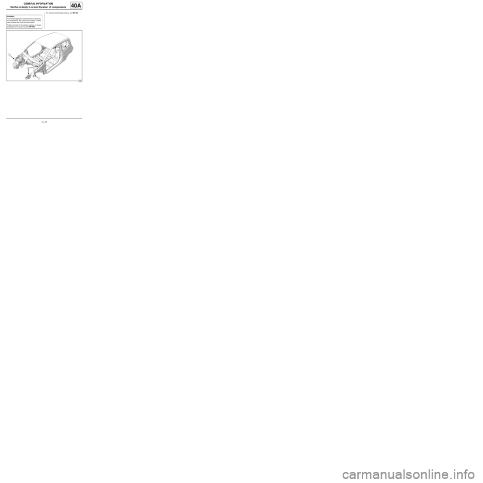
For the earth stud fitting procedure, see MR 400.
WARNING
To avoid damaging the vehicles electric and electro-
nic components, the earths of any wiring harness
near the weld area must be disconnected.
Position the earth of the welding machine as closely
as possible to the weld area (see MR 400).
121241
Page 40 of 209
41A-1
FRONT LOWER STRUCTURE
Front end lower cross member: General description
41A
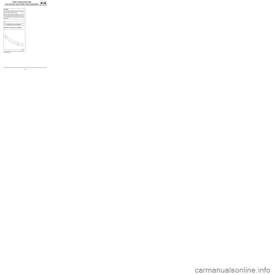
DESIGN OF THE STRUCTURAL COMPONENT
A special feature of this part is that it is welded to the
front side members.WARNING
The information contained in the following descri-
bes the general repair procedure for all vehicles
having the same design for this part.
Before reading this general information, check that
there are no special notes associated with this vehi-
cle. These special notes are specified if necessary
in other parts of the sub-section dealing with the
component.
Note:
For a detailed description of a particular connec-
tion, see MR 400, 40A, General Information.
110524
Page 41 of 209
41A-2
FRONT LOWER STRUCTURE
Front end lower cross member: Description
41A
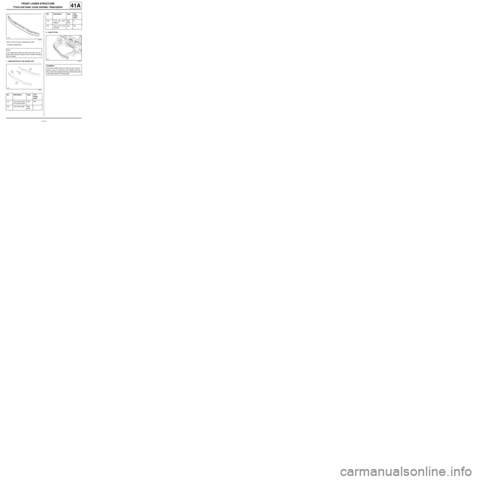
There is only one way of replacing this part:
-complete replacement.
I - COMPOSITION OF THE SPARE PARTII - PART FITTED
120675
Note:
The repair bench does not have to be used, on con-
dition that the side members have not been affected
by the impact.
120676
No. Description Type Thic-
kness
(mm)
(1) Front cross mem-
ber closure panelHLE1.5
(2) Tow hitch socket Mild
steel-
(3) Front tow hitch
supportMild
steel3
(4) Front end cross
memberHLE1.5
120677
WARNING
If the spot welds cannot be made as they were ori-
ginally using an electrical spot welding machine,
they should be replaced with plug welds after holes
have been drilled in the first panel. No. Description Type Thic-
kness
(mm)
Page 45 of 209
41A-6
FRONT LOWER STRUCTURE
Front side member: General description
41A
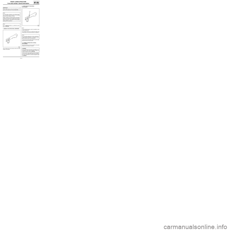
I - DESIGN OF THE STRUCTURAL COMPONENT
This is a basic part; its only function is that of front side
member, front section.II - AREA TO BE CUT FOR PARTIAL
REPLACEMENT
Cut 1:
This line marks the place in which it is possible to make
a partial replacement.
This operation allows you to access the inside of the
hollow section of the structural element to straighten it.
In this case, the side member weld line must be stag-
gered from that of its closure panel.
III - ASSEMBLY METHOD FOR A PARTIAL
REPLACEMENT
Only the connections which are specific to the partial
replacement by cutting are indicated.
If there are other issues regarding access to mating fa-
ces, the various replacement options are described in
the basic instructions for structural bodywork repair
(see MR 400). IMPORTANT
Use a repair bench to ensure the positioning of the
points and the geometr y of the axle assemblies.
Note:
The information contained in the following descri-
bes the general repair procedure for all vehicles
having the same design for this part.
Before reading the following general information,
make sure that there are no special notes associa-
ted with the vehicle. These special notes are speci-
fied if necessary in other par ts of the sub-section
dealing with the component.
Note:
For a detailed description of a particular connec-
tion, see MR 400.
110548
110549
Note:
For the partial replacement of parts constituting a
single structural component, it is essential to stag-
ger the welds of each of the components.
WARNING
If the mating faces of the parts to be welded are not
accessible, make EGW plug welds to replace the
original resistance welds (see MR 400).
Page 48 of 209
41A-9
FRONT LOWER STRUCTURE
Front side member, front section: Description
41A
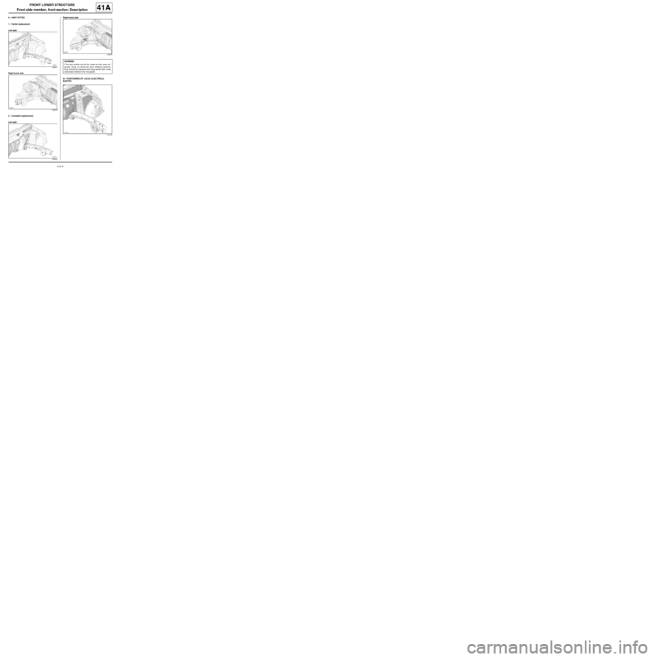
II - PART FITTED
1 - Partial replacement
Left side
Right-hand side
2 - Complete replacement
Left sideRight-hand side
III - POSITIONING OF LOCAL ELECTRICAL
EARTHS
120671
120672
120673
120674
WARNING
If the spot welds cannot be made as they were ori-
ginally using an electrical spot welding machine,
they should be replaced with plug welds after holes
have been drilled in the first panel.
121245
Page 50 of 209
41A-11
FRONT LOWER STRUCTURE
Front side member closure panel, front section: General description41A
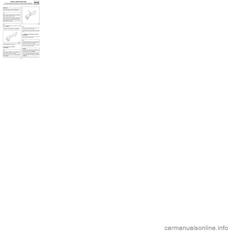
I - DESIGN OF THE STRUCTURAL COMPONENT
This is a basic part; its only function is that of front side
member closure panel, front section.
II - AREA TO BE CUT FOR PARTIAL
REPLACEMENT
For removal of the side member (see Front side mem-
ber: Description) .Cut 1:
This line shows the centre of the area in which it is pos-
sible to carry out a partial replacement.
This operation allows you to access the inside of the
hollow section of the structural component to straigh-
ten it.
III - ASSEMBLY INSTRUCTIONS FOR A PARTIAL
REPLACEMENT
In this case, the side member weld line must be stag-
gered from that of its closure panel.
Only the connections which are specific to the partial
replacement by cutting are indicated.
If there are other issues regarding access to mating fa-
ces, the various replacement options are described in
the basic instructions for structural bodywork repair
(see MR 400). IMPORTANT
Use a repair bench to ensure the positioning of the
points and the geometr y of the axle assemblies.
Note:
The information contained in the following descri-
bes the general repair procedure for all vehicles
having the same design for this part.
Before reading the following general information,
make sure that there are no special notes associa-
ted with the vehicle. These special notes are speci-
fied if necessary in other par ts of the sub-section
dealing with the component.
Note:
For a detailed description of a particular connec-
tion, see MR 400.
109550
Note:
For the partial replacement of parts constituting a
single structural component, it is essential to stag-
ger the welds of each of the components.
110553
Note:
For the partial replacement of parts constituting a
single structural component, it is essential to stag-
ger the welds of each of the components.
WARNING
If the mating faces of the parts to be welded are not
accessible, make EGW plug welds to replace the
original resistance welds (see MR 400).
Page 53 of 209
41A-14
FRONT LOWER STRUCTURE
Front side member closure panel, front section: Description41A
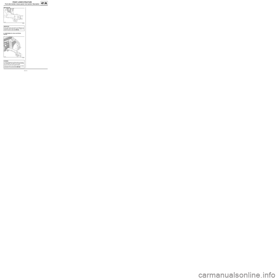
Right-hand side
III - POSITIONING OF LOCAL ELECTRICAL
EARTHS
120640
IMPORTANT
If the mating faces of the parts to be welded are not
accessible, make EGW plug welds to replace the
original resistance welds (see MR 400).
121245
WARNING
To avoid damaging the vehicles electric and electro-
nic components, the earths of any wiring harness
near the weld area must be disconnected.
Position the earth of the welding machine as closely
as possible to the weld area (see MR 400).
Page 54 of 209
41A-15
FRONT LOWER STRUCTURE
Front side member, rear section: Description
41A
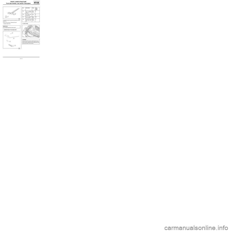
To replace this part, also order the centre floor reinfor-
cement (1) .
There is only one way of replacing this part:
-complete replacement.
I - COMPOSITION OF THE SPARE PARTII - PART FITTED
120635
IMPORTANT
The straightening bench must be used.
120636
No. Description Type Thic-
kness
(mm)
(2) Front subframe
rear mounting
stiffenerMild
steel2
(3) Front side mem-
ber rear partHLE2
(4) Front subframe
rear mountingMild
steel2.5
(5) Centre floor front
side cross mem-
berMild
steel1
120637
WARNING
If the spot welds cannot be made as they were ori-
ginally using an electrical spot welding machine,
they should be replaced with plug welds after holes
have been drilled in the first panel.