warning RENAULT TWINGO 2009 2.G Panelwork User Guide
[x] Cancel search | Manufacturer: RENAULT, Model Year: 2009, Model line: TWINGO, Model: RENAULT TWINGO 2009 2.GPages: 209
Page 57 of 209
41A-18
FRONT LOWER STRUCTURE
Front subframe front mounting: Description
41A
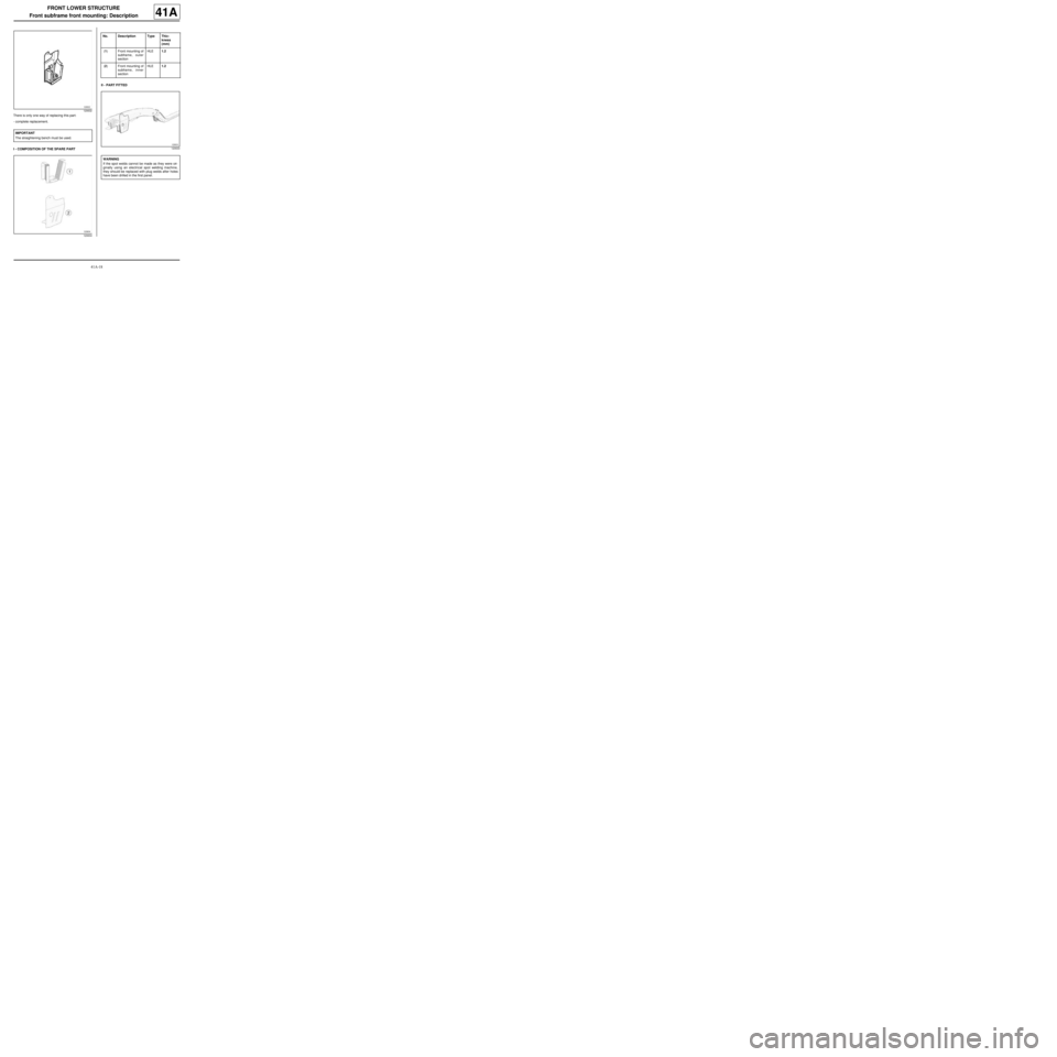
There is only one way of replacing this part:
-complete replacement.
I - COMPOSITION OF THE SPARE PARTII - PART FITTED
120632
IMPORTANT
The straightening bench must be used.
120634
No. Description Type Thic-
kness
(mm)
(1) Front mounting of
subframe, outer
sectionHLE1.2
(2) Front mounting of
subframe, inner
sectionHLE1.2
120633
WARNING
If the spot welds cannot be made as they were ori-
ginally using an electrical spot welding machine,
they should be replaced with plug welds after holes
have been drilled in the first panel.
Page 60 of 209
41A-21
FRONT LOWER STRUCTURE
Engine stand: Description
41A
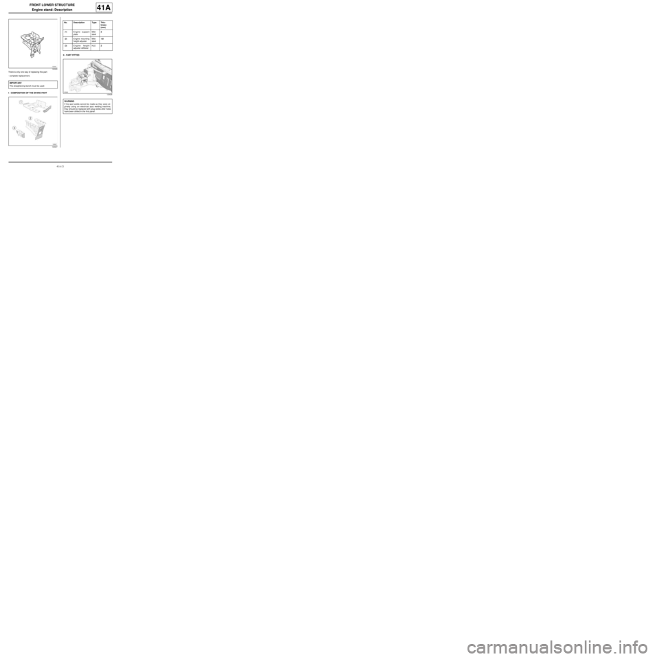
There is only one way of replacing this part:
-complete replacement.
I - COMPOSITION OF THE SPARE PARTII - PART FITTED
120626
IMPORTANT
The straightening bench must be used.
120627
No. Description Type Thic-
kness
(mm)
(1) E ngine support
plateMild
steel2
(2) Engine mounting
height adjusterMild
steel1.8
(3) Engine height
adjuster stiffenerHLE2
120628
WARNING
If the spot welds cannot be made as they were ori-
ginally using an electrical spot welding machine,
they should be replaced with plug welds after holes
have been drilled in the first panel.
Page 64 of 209
41A-25
FRONT LOWER STRUCTURE
Front half unit: Description
C44
41A
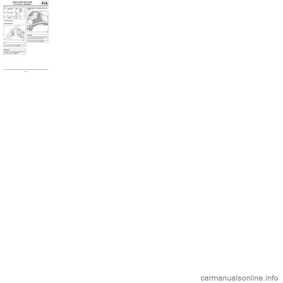
II - PART IN POSITION
Complete replacementIII - POSITIONING OF THE NEARBY ELECTRICAL
EARTHS
(8) Engine stand HEL/
Mild
steel2
(9) Front cup height
adjusterMild
steel1.3
120629
Note:
For more detailed information on welded connec-
tions with three thicknesses, see MR 400.
IMPORTANT
If the mating faces of the parts to be welded are not
accessible, use EGW plug welds instead of the ori-
ginal resistance welds (see MR 400) No. Description Type Thic-
kness
(mm)
121246
WARNING
To avoid damaging the vehicles electric and electro-
nic components, the earths of any wiring harness
near the weld area must be disconnected.
Position the earth of the welding machine as closely
as possible to the weld area (see MR 400).
Page 65 of 209
41B-1
CENTRE LOWER STRUCTURE
Centre floor, side section: General description
41B
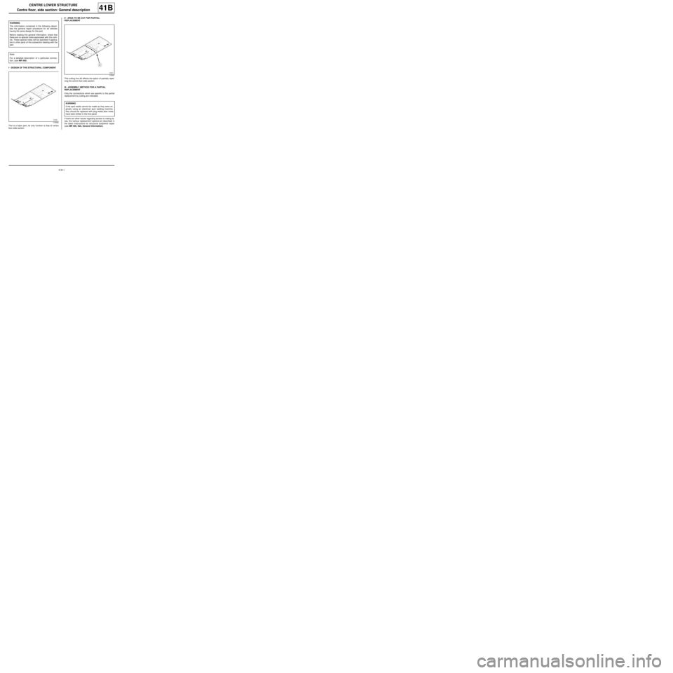
I - DESIGN OF THE STRUCTURAL COMPONENT
This is a basic part; its only function is that of centre
floor side section.II - AREA TO BE CUT FOR PARTIAL
REPLACEMENT
This cutting line (4) affects the option of partially repla-
cing the centre floor side section.
III - ASSEMBLY METHOD FOR A PARTIAL
REPLACEMENT
Only the connections which are specific to the partial
replacement by cutting are indicated.
If there are other issues regarding access to mating fa-
ces, the various replacement options are described in
the basic instructions for structural bodywork repair
(see MR 400, 40A, General Information). WARNING
The information contained in the following descri-
bes the general repair procedure for all vehicles
having the same design for this part.
Before reading this general information, check that
there are no special notes associated with this vehi-
cle. These special notes will be specified if applica-
ble in other parts of this subsection dealing with the
par t.
Note:
For a detailed description of a particular connec-
tion, (see MR 400).
110540
110541
WARNING
If the spot welds cannot be made as they were ori-
ginally using an electrical spot welding machine,
they should be replaced with plug welds after holes
have been drilled in the first panel.
Page 67 of 209
41B-3
CENTRE LOWER STRUCTURE
Centre floor, side section: Description
41B
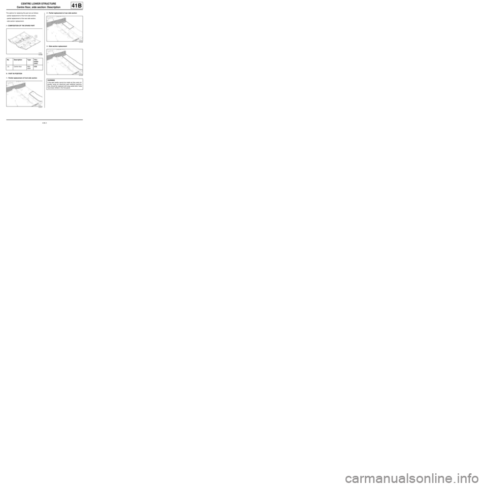
The options for replacing this part are as follows:
-partial replacement of the front side section,
-partial replacement of the rear side section,
-side section replacement.
I - COMPOSITION OF THE SPARE PART
II - PART IN POSITION
1 - Partial replacement of front side section2 - Partial replacement of rear side section
3 - Side section replacement
121058
No. Description Type Thic-
kness
(mm)
(1) Centre floor Mild
steel0.95
121917
121916
121918
WARNING
If the spot welds cannot be made as they were ori-
ginally using an electrical spot welding machine,
they should be replaced with plug welds after holes
have been drilled in the first panel.
Page 70 of 209
41B-6
CENTRE LOWER STRUCTURE
Centre floor front side cross member: General description41B
If there are other issues regarding access to mating fa-
ces, the various replacement options are described in
the basic instructions for structural bodywork repair
(see MR 400).
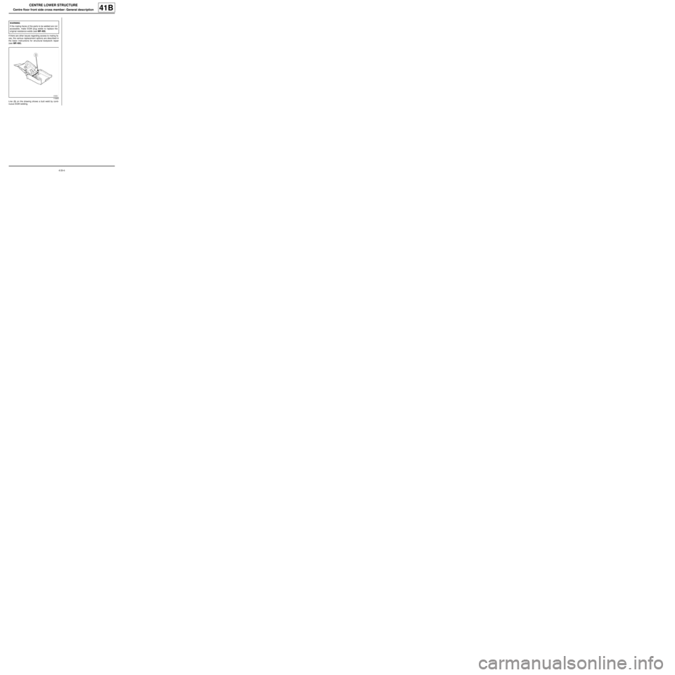
Line (3) on the drawing shows a butt weld by conti-
nuous EGW welding.WARNING
If the mating faces of the parts to be welded are not
accessible, make EGW plug welds to replace the
original resistance welds (see MR 400).
110600
Page 71 of 209
41B-7
CENTRE LOWER STRUCTURE
Centre floor front side cross member: Description
41B
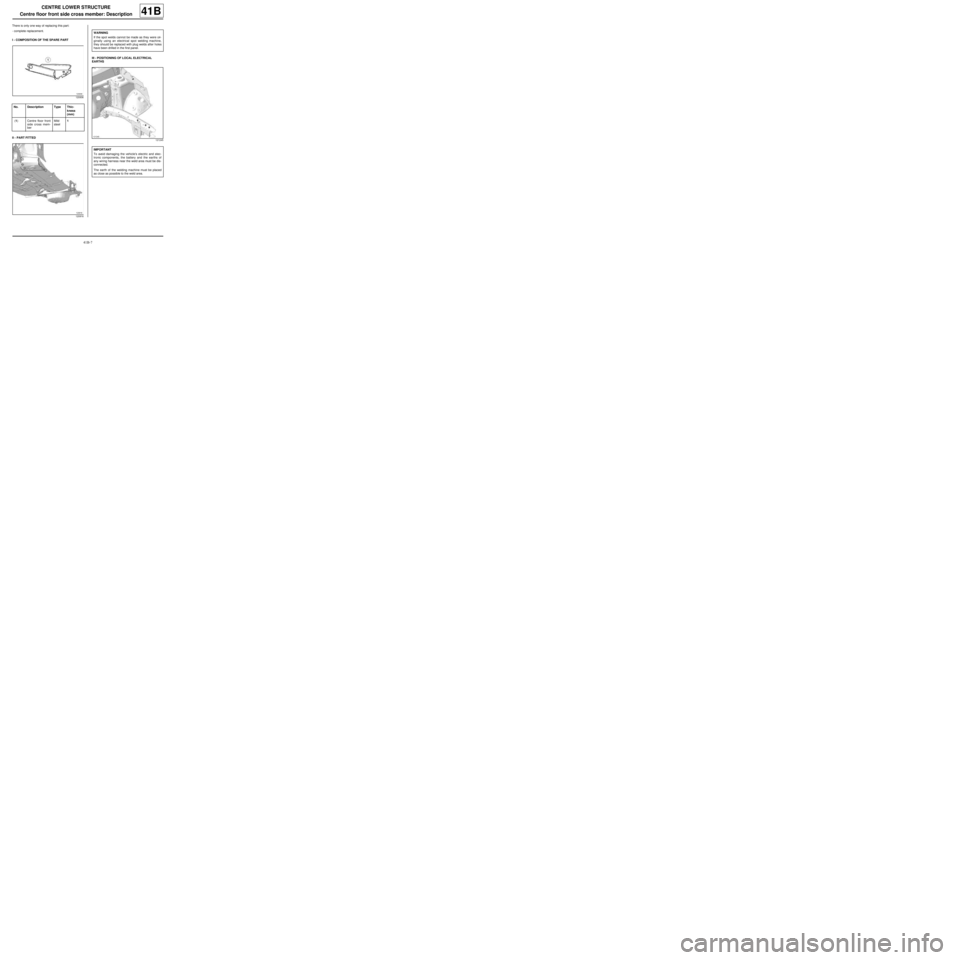
There is only one way of replacing this part:
-complete replacement.
I - COMPOSITION OF THE SPARE PART
II - PART FITTEDIII - POSITIONING OF LOCAL ELECTRICAL
EARTHS
120936
No. Description Type Thic-
kness
(mm)
(1) Centre floor front
side cross mem-
berMild
steel1
120916
WARNING
If the spot welds cannot be made as they were ori-
ginally using an electrical spot welding machine,
they should be replaced with plug welds after holes
have been drilled in the first panel.
121245
IMPORTANT
To avoid damaging the vehicle's electric and elec-
tronic components, the battery and the earths of
any wiring harness near the weld area must be dis-
connected.
The earth of the welding machine must be placed
as close as possible to the weld area.
Page 73 of 209
41B-9
CENTRE LOWER STRUCTURE
Front cross member under front seat: Description
C44
41B
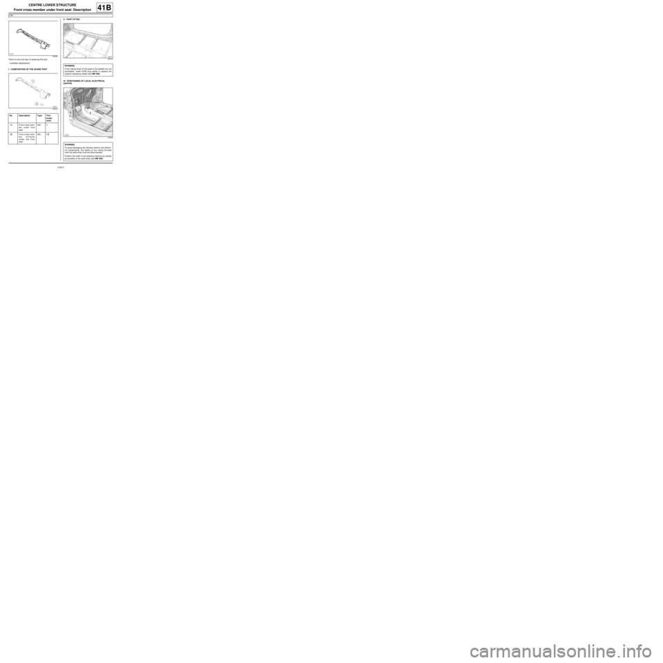
There is only one way of replacing this part:
-complete replacement.
I - COMPOSITION OF THE SPARE PARTII - PART FITTED
III - POSITIONING OF LOCAL ELECTRICAL
EARTHS
120935
120914
No. Description Type Thic-
kness
(mm)
(1) Front cross mem-
ber under front
seatHEL1
(2) Front cross mem-
ber stiffener
under the front
seatHEL1.2
120915
WARNING
If the mating faces of the parts to be welded are not
accessible, make EGW plug welds to replace the
original resistance welds (see MR 400).
125408
WARNING
To avoid damaging the vehicles electric and electro-
nic components, the earths of any wiring harness
near the weld area must be disconnected.
Position the earth of the welding machine as closely
as possible to the weld area (see MR 400).
Page 75 of 209
41B-11
CENTRE LOWER STRUCTURE
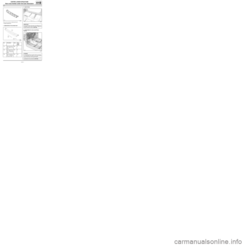
Rear cross member under front seat: Description
C44
41B
There is only one way of replacing this part:
-complete replacement.
I - COMPOSITION OF THE SPARE PARTII - PART FITTED
III - POSITIONING OF LOCAL ELECTRICAL
EARTHS
120934
120912
No. Description Type Thic-
kness
(mm)
(1) Rear cross mem-
ber under front
seatHEL1
(2) Rear cross mem-
ber under front
seat mounting
plateHEL2
(3) Rear cross mem-
ber stiffener
under front seatHEL1.2
120913
IMPORTANT
If the mating faces of the parts to be welded are not
accessible, make EGW plug welds to replace the
original resistance welds (see MR 400).
125408
WARNING
To avoid damaging the vehicles electric and electro-
nic components, the earths of any wiring harness
near the weld area must be disconnected.
Position the earth of the welding machine as closely
as possible to the weld area (see MR 400).
Page 79 of 209
41C-4
SIDE LOWER STRUCTURE
Sill panel: General description
41C
If there are other issues regarding access to mating fa-
ces, the various replacement options are described in
the basic instructions for structural bodywork repair
(see MR 400).
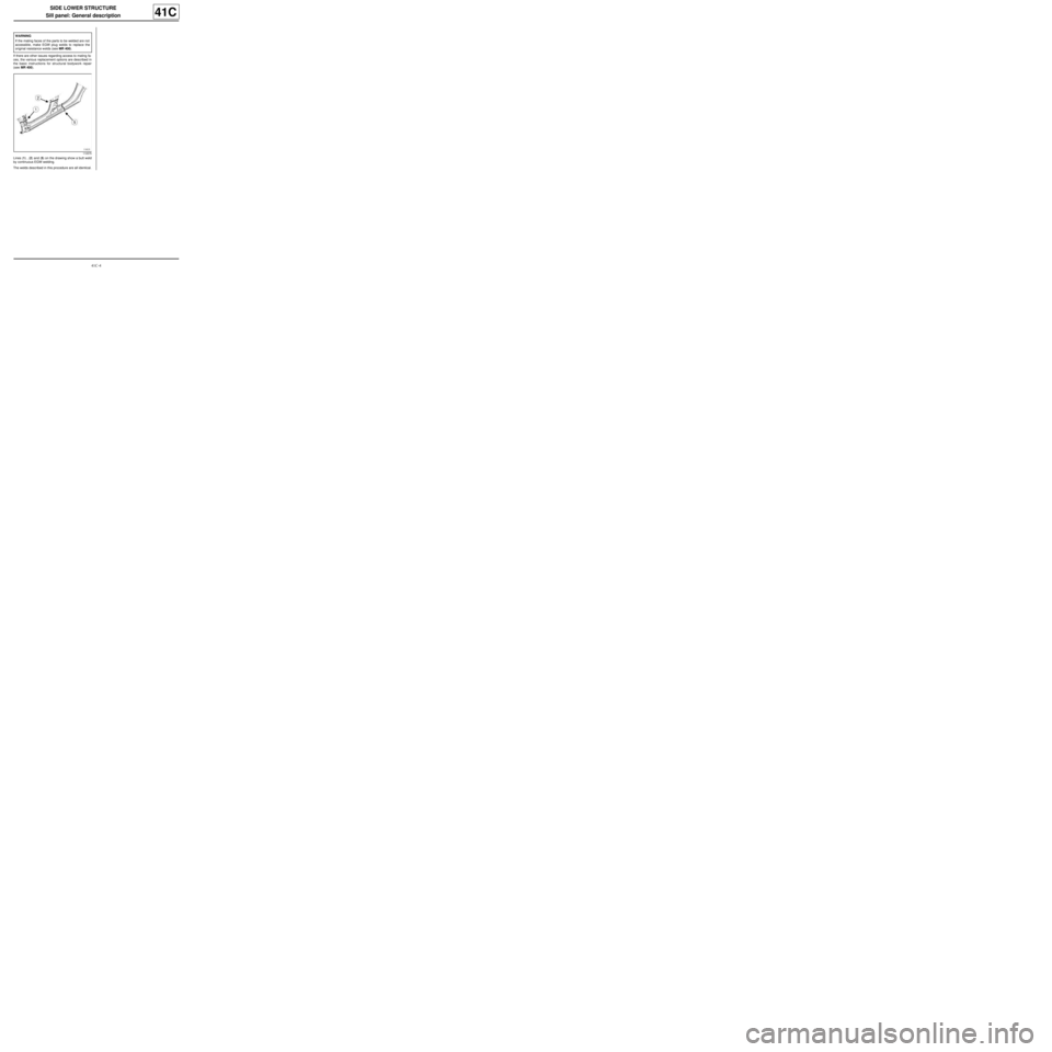
Lines (1) , (2) and (5) on the drawing show a butt weld
by continuous EGW welding.
The welds described in this procedure are all identical.WARNING
If the mating faces of the parts to be welded are not
accessible, make EGW plug welds to replace the
original resistance welds (see MR 400).
110575