warning RENAULT TWINGO 2009 2.G Panelwork Service Manual
[x] Cancel search | Manufacturer: RENAULT, Model Year: 2009, Model line: TWINGO, Model: RENAULT TWINGO 2009 2.GPages: 209
Page 135 of 209
42A-26
FRONT UPPER STRUCTURE
Dashboard cross member: Removal - Refitting
42A
REMOVAL
a
I - REMOVAL PREPARATION OPERATION
aLock the airbag computer using the Diagnostic tool
(see Fault finding - Replacement of components)
(MR 413, 88C, Airbags and pretensioners).
aDisconnect the battery (see Battery: Removal - Re-
fitting) (MR 411, 80A, Battery).
aRemove:
-the dashboard (see Dashboard: Removal - Refit-
ting) (MR 412, 57A, Interior equipment),
-the steering column (see Steering column: Re-
moval - Refitting) (MR 411, 36A, Steering assem-
bly).II - OPERATION FOR REMOVAL OF PART
CONCERNED
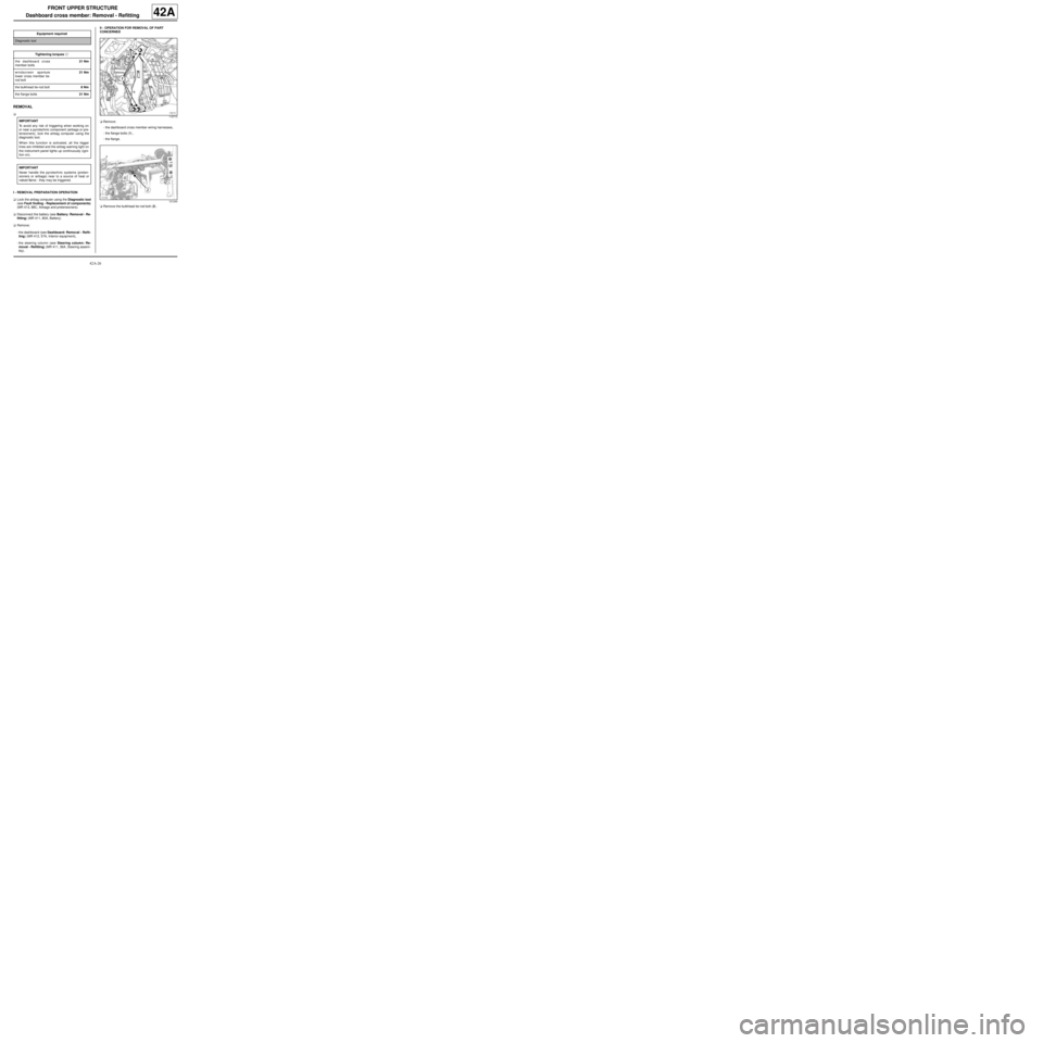
aRemove:
-the dashboard cross member wiring harnesses,
-the flange bolts (1) ,
-the flange.
aRemove the bulkhead tie-rod bolt (2) . Equipment required
Diagnostic tool
Tightening torquesm
the dashboard cross
member bolts21 Nm
windscreen aperture
lower cross member tie-
rod bolt21 Nm
the bulkhead tie-rod bolt8 Nm
the flange bolts21 Nm
IMPORTANT
To avoid any risk of triggering when working on
or near a pyrotechnic component (airbags or pre-
tensioners), lock the airbag computer using the
diagnostic tool.
When this function is activated, all the trigger
lines are inhibited and the airbag warning light on
the instrument panel lights up continuously (igni-
tion on).
IMPORTANT
Never handle the pyrotechnic systems (preten-
sioners or airbags) near to a source of heat or
naked flame - they may be triggered.
119713
121240
Page 137 of 209
42A-28
FRONT UPPER STRUCTURE
Windscreen aperture lower cross member closure panel: Description42A
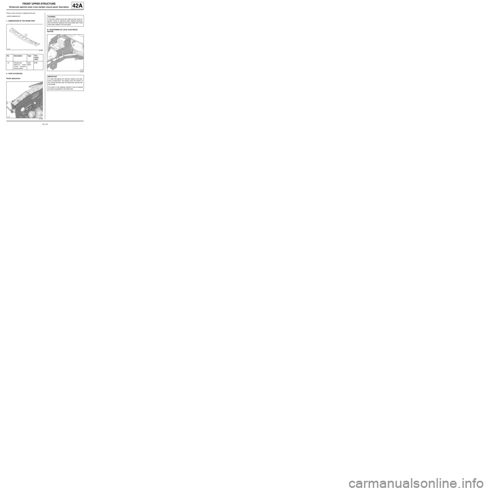
There is only one way of replacing this part:
-partial replacement.
I - COMPOSITION OF THE SPARE PART
II - PART IN POSITION
Partial replacementIII - POSITIONING OF LOCAL ELECTRICAL
EARTHS
121055
No. Description Type Thic-
kness
(mm)
(1) Windscreen
apert u r e l o wer
cross member
closure panelMild
steel0.75
121238
WARNING
If the spot welds cannot be made as they were ori-
ginally using an electrical spot welding machine,
they should be replaced with plug welds after holes
have been drilled in the first panel.
121246
IMPORTANT
To avoid damaging the vehicle's electric and elec-
tronic components, the battery and the earths of
any wiring harness near the weld area must be dis-
connected.
The earth of the welding machine must be placed
as close as possible to the weld area.
Page 138 of 209
43A-1
SIDE UPPER STRUCTURE
A-pillar: General description
43A
DESIGN OF THE STRUCTURAL COMPONENT
The design of this part is identical for all three vehicles.
On the Modus, the A-pillar is obtained by extension
from the body side front section.WARNING
The information contained in the following descri-
bes the general repair procedure for all vehicles
having the same design for this part.
Before reading the following general information,
make sure that there are no special notes associa-
ted with the vehicle. These special notes are speci-
fied if necessary in other par ts of the sub-section
dealing with the component.
Note:
For a detailed description of a particular connec-
tion, see MR 400, 40A, General Information.
109562
WARNING
If the spot welds cannot be made as they were ori-
ginally using an electrical spot welding machine,
they should be replaced with plug welds after holes
have been drilled in the first panel.
Page 140 of 209
43A-3
SIDE UPPER STRUCTURE
A-pillar: Description
43A
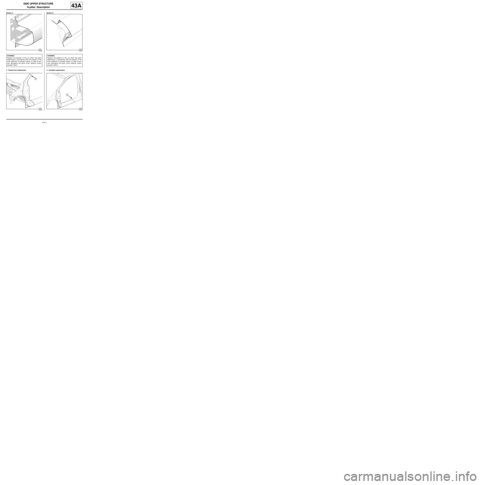
Section C
2 - Partial front replacementSection D
3 - Complete replacement
120994
WARNING
Respect the position of this cut which has been
determined in accordance with the position of the
inner stiffeners or acoustic inserts, in order to pre-
vent damaging the parts (inner stiffener and/or
acoustic inser t).
120993
120996
WARNING
Respect the position of this cut which has been
determined in accordance with the position of the
inner stiffeners or acoustic inserts, in order to pre-
vent damaging the parts (inner stiffener and/or
acoustic inser t).
120990
Page 141 of 209
43A-4
SIDE UPPER STRUCTURE
A-pillar: Description
43A
Section E III - POSITIONING OF LOCAL ELECTRICAL
EARTHS
120989
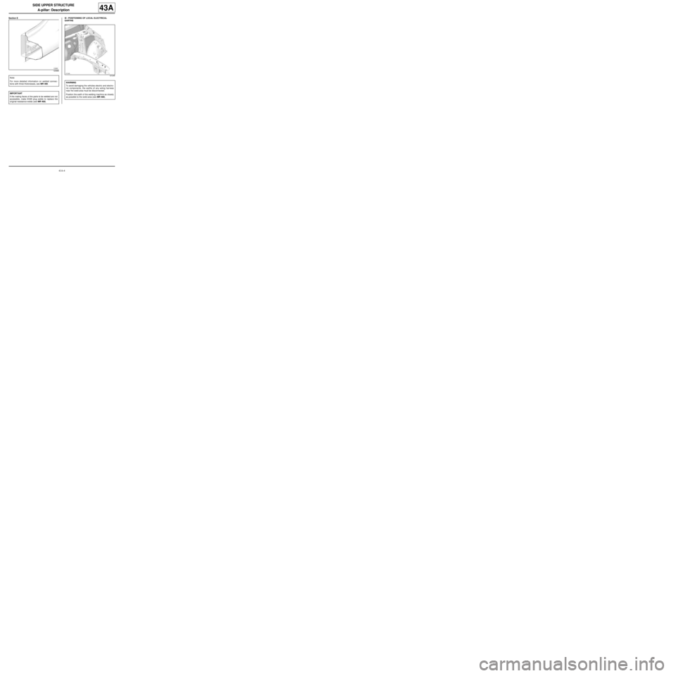
Note:
For more detailed information on welded connec-
tions with three thicknesses, see MR 400.
IMPORTANT
If the mating faces of the parts to be welded are not
accessible, make EGW plug welds to replace the
original resistance welds (see MR 400).
121245
WARNING
To avoid damaging the vehicles electric and electro-
nic components, the earths of any wiring harness
near the weld area must be disconnected.
Position the earth of the welding machine as closely
as possible to the weld area (see MR 400).
Page 142 of 209
43A-5
SIDE UPPER STRUCTURE
A-pillar reinforcement: General description
43A
DESIGN OF THE STRUCTURAL COMPONENT
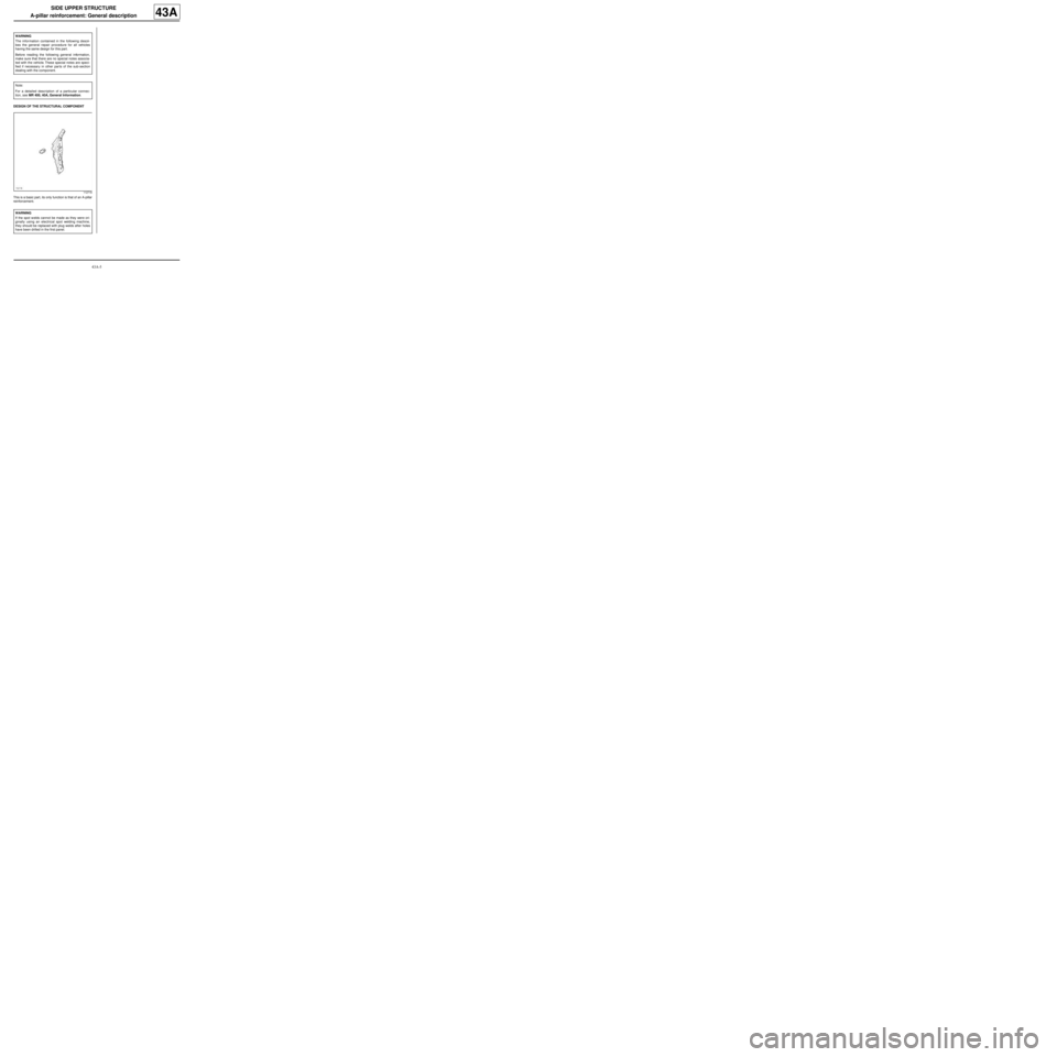
This is a basic part, its only function is that of an A-pillar
reinforcement.WARNING
The information contained in the following descri-
bes the general repair procedure for all vehicles
having the same design for this part.
Before reading the following general information,
make sure that there are no special notes associa-
ted with the vehicle. These special notes are speci-
fied if necessary in other par ts of the sub-section
dealing with the component.
Note:
For a detailed description of a particular connec-
tion, see MR 400, 40A, General Information.
112718
WARNING
If the spot welds cannot be made as they were ori-
ginally using an electrical spot welding machine,
they should be replaced with plug welds after holes
have been drilled in the first panel.
Page 144 of 209
43A-7
SIDE UPPER STRUCTURE
A-pillar reinforcement: Description
C44
43A
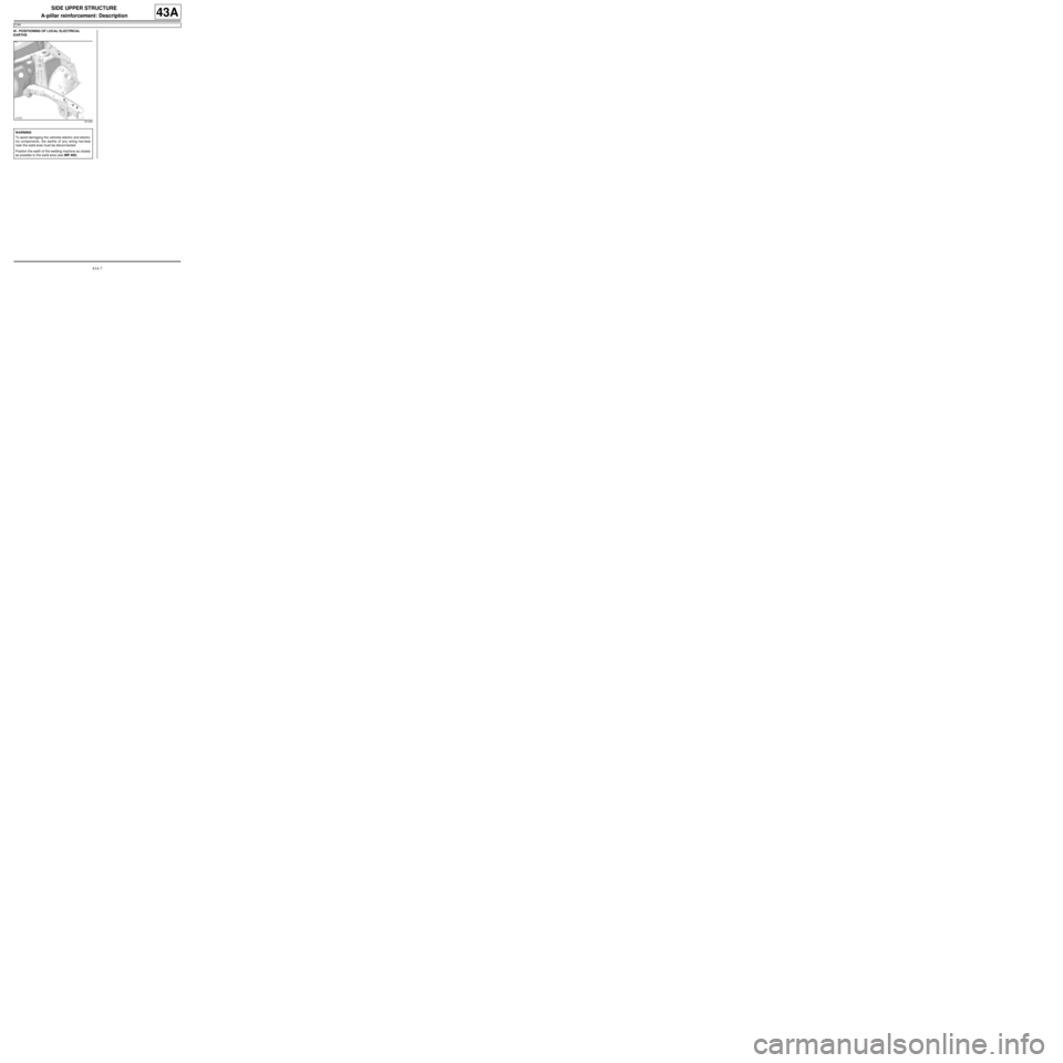
III - POSITIONING OF LOCAL ELECTRICAL
EARTHS
121245
WARNING
To avoid damaging the vehicles electric and electro-
nic components, the earths of any wiring harness
near the weld area must be disconnected.
Position the earth of the welding machine as closely
as possible to the weld area (see MR 400).
Page 146 of 209

43A-9
SIDE UPPER STRUCTURE
B-pillar reinforcement: General description
43A
I - DESIGN OF THE STRUCTURAL COMPONENT
The special feature of this part is that it combines seve-
ral functions:
-B-pillar reinforcement,
-quarter panel reinforcement.
II - AREA TO BE CUT FOR PARTIAL
REPLACEMENT
III - ASSEMBLY METHOD FOR A PARTIAL
REPLACEMENT
Only the connections which are specific to the partial
replacement by cutting are indicated.If there are other issues regarding access to mating fa-
ces, the various options are described in the basic ins-
tructions for structural bodywork repair (see MR 400).
Line (2) on the drawing shows a butt weld by conti-
nuous EGW welding. Note:
The information contained in the following descri-
bes the general repair procedure for all vehicles
having the same design for this part.
Before reading the following general information,
make sure that there are no special notes associa-
ted with the vehicle. These special notes are speci-
fied if necessary in other par ts of the sub-section
dealing with the component.
Note:
For a detailed description of a particular connec-
tion, see MR 400.
121054
WARNING
If the mating faces of the parts to be welded are not
accessible, make EGW plug welds to replace the
original resistance welds (see MR 400).
101971
Page 147 of 209
43A-10
SIDE UPPER STRUCTURE
B-pillar reinforcement: Description
43A
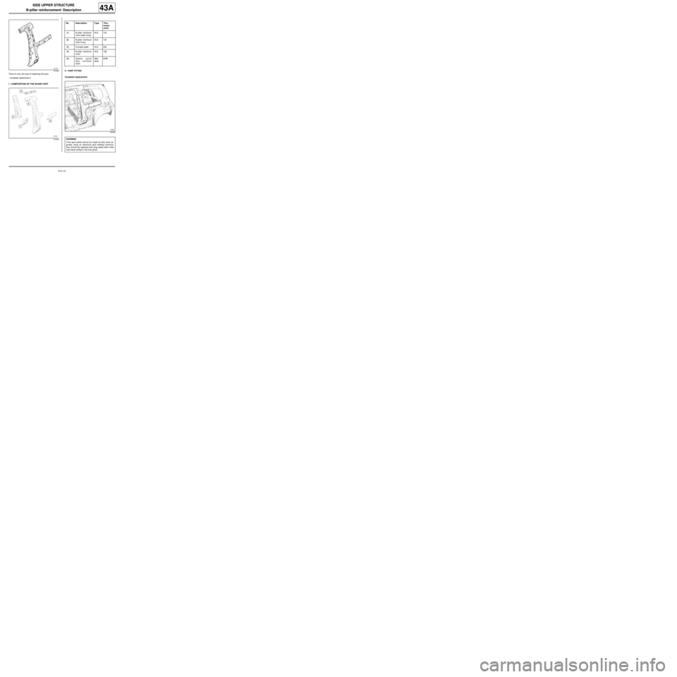
There is only one way of replacing this part:
-complete replacement.
I - COMPOSITION OF THE SPARE PARTII - PART FITTED
Complete replacement
121054
121000
No. Description Type Thic-
kness
(mm)
(1) B-pillar reinforce-
ment lower liningHLE1.2
(2) B-pillar reinforce-
ment liningHLE1.4
(3) Crumple plate HLE2.5
(4) B-pillar reinforce-
mentHLE1.8
(5) Quart e r p a n e l
strip reinforce-
mentMild
steel0.75
120999
WARNING
If the spot welds cannot be made as they were ori-
ginally using an electrical spot welding machine,
they should be replaced with plug welds after holes
have been drilled in the first panel.
Page 149 of 209
43A-12
SIDE UPPER STRUCTURE
Body side: General description
43A
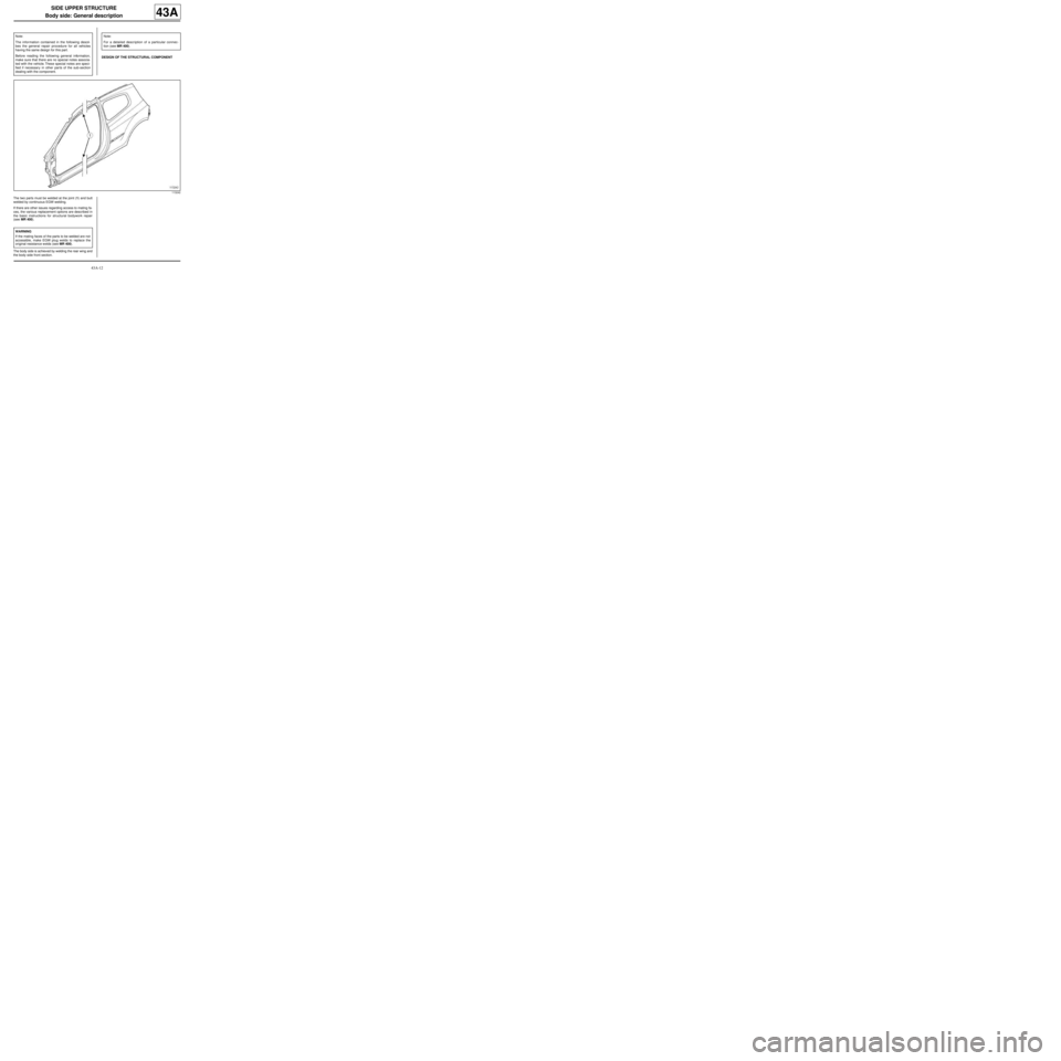
DESIGN OF THE STRUCTURAL COMPONENT
The two parts must be welded at the joint (1) and butt
welded by continuous EGW welding.
If there are other issues regarding access to mating fa-
ces, the various replacement options are described in
the basic instructions for structural bodywork repair
(see MR 400).
The body side is achieved by welding the rear wing and
the body side front section.Note:
The information contained in the following descri-
bes the general repair procedure for all vehicles
having the same design for this part.
Before reading the following general information,
make sure that there are no special notes associa-
ted with the vehicle. These special notes are speci-
fied if necessary in other par ts of the sub-section
dealing with the component.
Note:
For a detailed description of a particular connec-
tion (see MR 400).
113242
WARNING
If the mating faces of the parts to be welded are not
accessible, make EGW plug welds to replace the
original resistance welds (see MR 400).