RENAULT TWINGO 2009 2.G Transmission Repair Manual
Manufacturer: RENAULT, Model Year: 2009, Model line: TWINGO, Model: RENAULT TWINGO 2009 2.GPages: 135
Page 51 of 135
21A-36
MANUAL GEARBOX
Manual gearbox: Repair
JH1 or JH3 or JR5
21A
REMOVAL
I - REPAIR PREPARATION OPERATION
aRemove the gearbox (see 21A, Manual gearbox,
Manual gearbox: Removal - Refitting, page 21A-
24) .
aPosition the gearbox on the component support (see
Gearbox support equipment: Use) .
II - REMOVAL OPERATION
aRemove:
-the fifth gear housing (see 5th gear housing: Re-
moval - Refitting) ,
-the fifth gear synchroniser and pinions (see 5th
gear sprockets and synchronisers: Removal -
Refitting) ,
-the mechanism housing (see Mechanism hous-
ing: Removal - Refitting) ,
-the gearbox shafts (see Gearbox shaft: Removal
- Refitting) ,
-the differential (see Manual gearbox differential:
Removal - Refitting) .
III - REPAIR OPERATION
aStrip down the output shaft (see Output shaft:
Stripping - Rebuilding) .
aRemove:
-the differential bearings (see Manual gearbox dif-
ferential bearing: Removal - Refitting) ,
-the bearings of the mechanism housing (see
Mechanism housing bearing: Removal - Refit-
ting) ,
-the bearings of the clutch housing (see Clutch
housing bearing: Removal - Refitting) ,
-the gearbox selector shaft (see Manual gearbox
selector shaft: Removal - Refitting) .aUse SURFACE CLEANER (see Vehicle: Parts
and consumables for the repair) to clean all of the
removed parts.
aCheck (see Manual gearbox: Check) :
-the pinions (teeth, claws, friction cone, inner wall),
-the synchroniser hubs,
-the synchroniser rings,
-the bearings.
aReplace worn or damaged parts.
REFITTING
I - REFITTING PREPARATION OPERATION
aParts always to be replaced:
-the lip seals,
-the O-rings,
-the clutch thrust bearing guide,
-the gear lock rings,
-the roll pins,
-the input and output shaft bearing circlips,
-the selector rod hub springs,
-the hydraulic clutch slave cylinder (if fitted),
-the magnet,
-the selector shaft rings,
-the lock ring of the differential,
-the differential retaining nut.
II - REFITTING OPERATION
aRefit:
-the gearbox selector shaft (see Manual gearbox
selector shaft: Removal - Refitting) ,
-the bearings of the clutch housing (see Clutch
housing bearing: Removal - Refitting) ,
-the bearings of the mechanism housing (see
Mechanism housing bearing: Removal - Refit-
ting) ,
-the differential bearings (see Manual gearbox dif-
ferential bearing: Removal - Refitting) .
aRebuild the output shaft (see Output shaft: Strip-
ping - Rebuilding) . IMPORTANT
To avoid all risk of damage to the systems, apply
the safety and cleanliness instructions and opera-
tion recommendations before carrying out any
repair (see Manual gearbox: Precautions for the
repair) .
Page 52 of 135
21A-37
MANUAL GEARBOX
Manual gearbox: Repair
JH1 or JH3 or JR5
21A
III - REMOVAL OPERATION
aRefit:
-the differential (see Manual gearbox differential:
Removal - Refitting) ,
-the gearbox shafts (see Gearbox shaft: Removal
- Refitting) .
aAdjust the shafts (see Gearbox shaft: Adjustment)
if replacing a shaft or housing.
aRefit:
-the mechanism housing (see Mechanism hous-
ing: Removal - Refitting) ,
-the fifth gear synchroniser and pinions (see 5th
gear sprockets and synchronisers: Removal -
Refitting) ,
-the fifth gear housing (see 5th gear housing: Re-
moval - Refitting) .
IV - FINAL OPERATION
aRemove the gearbox from the component support
(see Gearbox support equipment: Use) .
aRefit the gearbox (see 21A, Manual gearbox, Man-
ual gearbox: Removal - Refitting, page 21A-24) .
Page 53 of 135
21A-38
MANUAL GEARBOX
Differential output seal: Removal - Refitting
JB1 or JH1 or JH3 or JR5
21A
REMOVAL
I - REMOVAL PREPARATION OPERATION
aPosition the vehicle on a two-post lift (see Vehicle:
Towing and lifting) (02A, Lifting equipment).
aRemove:
-the front right-hand wheel (see Wheel: Removal -
Refitting) (35A, Wheels and tyres),
-the front right-hand wheel driveshaft (see 29A,
Driveshafts, Front right-hand driveshaft: Re-
moval - Refitting, page 29A-8) .
aDrain the gearbox (see 21A, Manual gearbox,
Manual gearbox oils: Draining - Filling, page
21A-2) .
aRemove:
-the wheel on the side concerned (see Wheel: Re-
moval - Refitting) (35A, Wheels and tyres),
-the front wheel driveshaft for the side in question
(see 29A, Driveshafts, Front left-hand drive-
shaft: Removal - Refitting, page 29A-2) or (see
29A, Driveshafts, Front right-hand driveshaft:
Removal - Refitting, page 29A-8) .II - OPERATION FOR REMOVAL OF PART
CONCERNED
aTap the base of the differential output seal using a
roll pin punch and a small hammer to rotate it in its
housing.
aRemove the differential output seal using pliers, tak-
ing care not to damage the splines on the sunwheel. Special tooling required
Bvi. 945Mandrel for fitting the sun-
wheel seal.
Bvi. 1666Tool for fitting differential
seals .
Equipment required
roll pin punch
JB1 or JH1
JH3 or JR5
JB1 or JH1
86031
Page 54 of 135
21A-39
MANUAL GEARBOX
Differential output seal: Removal - Refitting
JB1 or JH1 or JH3 or JR5
21A
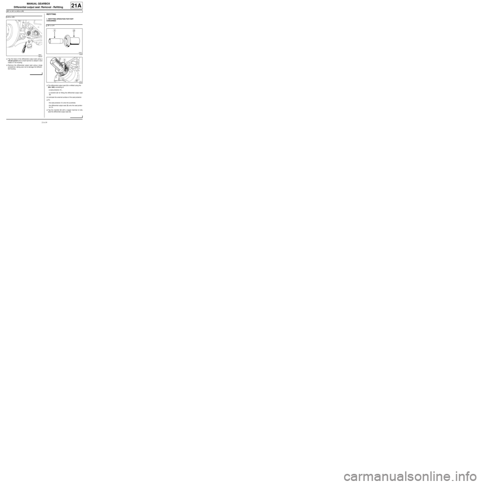
aTap the base of the differential output seal using a
roll pin punch and a small hammer to detach it and
rotate it in its housing.
aRemove the differential output seal using a large
screwdriver, taking care not to damage the differen-
tial housing.
REFITTING
I - REFITTING OPERATION FOR PART
CONCERNED
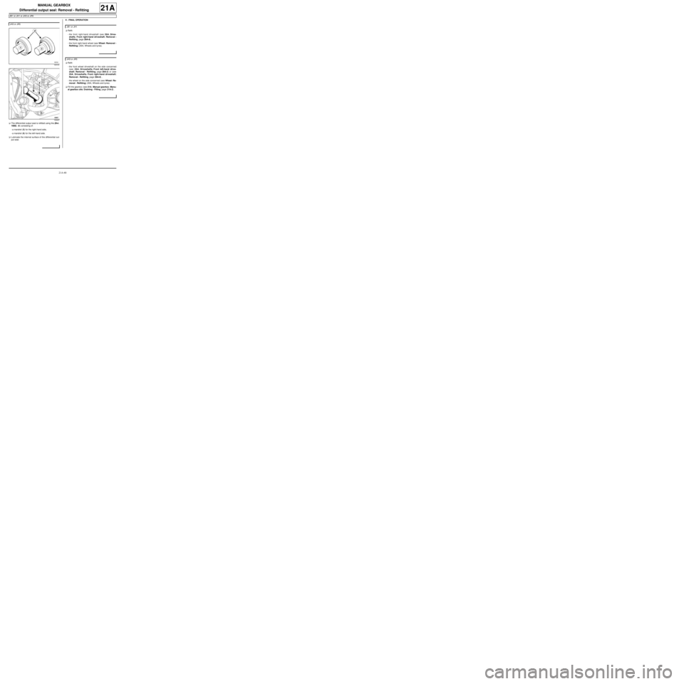
aThe differential output seal (3) is refitted using the
(Bvi. 945) consisting of:
-a seal protector (1) ,
-a mandrel (2) for fitting the differential output seal
(3) .
aLubricate the external surface of the seal protector.
aFit:
-the seal protector (1) onto the sunwheel,
-the differential output seal (3) onto the seal protec-
tor (1) .
aTap the mandrel (2) with a copper hammer to fully
seat the differential output seal (3) . JH3 or JR5
109147
JB1 or JH1
18150
86122
Page 55 of 135
21A-40
MANUAL GEARBOX
Differential output seal: Removal - Refitting
JB1 or JH1 or JH3 or JR5
21A
aThe differential output seal is refitted using the (Bvi.
1666) (4) consisting of:
-a mandrel (5) for the right-hand side,
-a mandrel (6) for the left-hand side.
aLubricate the internal surface of the differential out-
put seal.II - FINAL OPERATION
aRefit:
-the front right-hand driveshaft (see 29A, Drive-
shafts, Front right-hand driveshaft: Removal -
Refitting, page 29A-8) ,
-the front right-hand wheel (see Wheel: Removal -
Refitting) (35A, Wheels and tyres).
aRefit:
-the front wheel driveshaft on the side concerned
(see 29A, Driveshafts, Front left-hand drive-
shaft: Removal - Refitting, page 29A-2) or (see
29A, Driveshafts, Front right-hand driveshaft:
Removal - Refitting, page 29A-8) ,
-the wheel on the side concerned (see Wheel: Re-
moval - Refitting) (35A, Wheels and tyres).
aFill the gearbox (see 21A, Manual gearbox, Manu-
al gearbox oils: Draining - Filling, page 21A-2) . JH3 or JR5
103191
109407
JB1 or JH1
JH3 or JR5
Page 56 of 135
21A-41
MANUAL GEARBOX
Input shaft lip seal: Removal - Refitting
JB1
21A
Detailed view of the Bvi tool components. 1445
aThe gearbox must be removed.
REMOVAL
I - REMOVAL PREPARATION OPERATION
aPosition the vehicle on a two-post lift (see Vehicle:
Towing and lifting) (MR 411, 02A, Lifting equip-
ment).
aDisconnect the battery (see Battery: Removal - Re-
fitting) (MR 411, 80A, Battery).aRemove the gearbox (see 21A, Manual gearbox,
Manual gearbox: Removal - Refitting, page 21A-
24) .
II - OPERATION FOR REMOVAL OF PART
CONCERNED
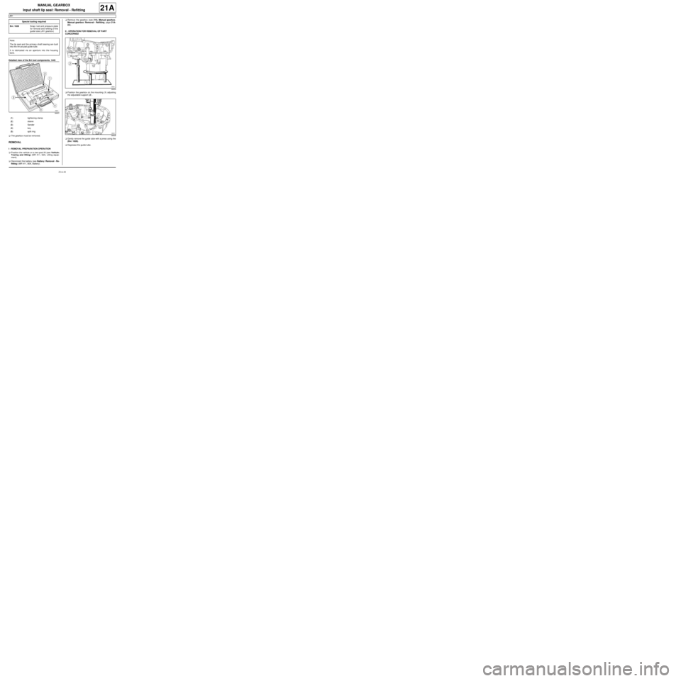
aPosition the gearbox on the mounting (1) adjusting
the adjustable support (2) .
aGently remove the guide tube with a press using the
(Bvi. 1828).
aDegrease the guide tube. Special tooling required
Bvi. 1828Snap r ivet and pressure plate
for removal and refitting of the
guide tube (JH1 gearbo x)
Note:
The lip seal and the primary shaft bearing are built
into the thr ust pad guide tube.
It is lubricated via an aperture into the housing
bore.
99057
(1) tightening clamp
(2) sleeve
(3) Sender
(4) key
(5) split ring
98934
98936
Page 57 of 135

21A-42
MANUAL GEARBOX
Input shaft lip seal: Removal - Refitting
JB1
21A
aPlace the tightening clamp (3) onto the tube.
aLock the tightening clamp using the spanner (4) .
aTighten the nut firmly (5) .
aPosition the sleeve (6) and the split ring (7) .
aTurn the upper nut (8) .
aGently extract the guide tube.
REFITTING
I - REFITTING OPERATION FOR PART
CONCERNED
aPosition the new guide tube on the clutch housing.
aGently remove the guide tube with a press and the
(Bvi. 1828).
II - FINAL OPERATION.
aRefit the gearbox (see 21A, Manual gearbox, Man-
ual gearbox: Removal - Refitting, page 21A-24)
(MR 411, 21A, Manual gearbox).
aConnect the battery (see Battery: Removal - Refit-
ting) (MR 411, 80A, Battery).
98937
98938
98939
98935-1
Page 58 of 135
21A-43
MANUAL GEARBOX
Input shaft lip seal: Removal - Refitting
JH1 or JH3 or JR5
21A
aReplace the lip seal after having opened the gear-
box (see Clutch housing bearing: Removal - Re-
fitting) (Technical Note 6029A, 21A, Manual
gearbox).
Page 59 of 135
21A-44
MANUAL GEARBOX
Reverse gear switch: Removal - Refitting
JB1 or JH1 or JH3 or JR5
21A
REMOVAL
I - REMOVAL PREPARATION OPERATION
aPosition the vehicle on a two-post lift (see Vehicle:
Towing and lifting) (02A, Lifting equipment).
aRemove:
-the front left-hand wheel (see Wheel: Removal -
Refitting) (35A, Wheels and tyres),
-the front left-hand wheel arch liner (see Front
wheel arch liner: Removal - Refitting) (55A, Ex-
terior protection).
aRemove the engine undertray.
II - OPERATION FOR REMOVAL OF PART
CONCERNED
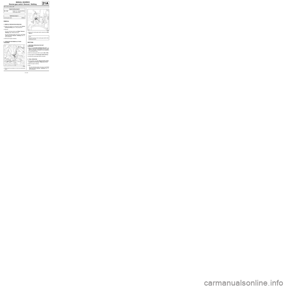
aDisconnect the connector (1) from the reverse gear
switch.aRemove the reverse gear switch using the tool (Bvi.
1934) (2) .
REFITTING
I - REFITTING OPERATION FOR PART
CONCERNED
aApply some SILICONE ADHESIVE SEALANT (see
Vehicle: Parts and consumables for the repair)
(04B, Consumables - Products) to the threading of
the reverse gear switch.
aRefit the reverse gear switch using the (Bvi. 1934).
aTorque tighten the reverse gear switch (23 N.m).
aConnect the reverse gear switch connector.
II - FINAL OPERATION
aFill the gearbox (see 21A, Manual gearbox, Manu-
al gearbox oils: Draining - Filling, page 21A-2) .
aRefit the engine undertray.
aRefit:
-the front left-hand wheel arch liner (see Front
wheel arch liner: Removal - Refitting) (55A, Ex-
terior protection), Special tooling required
Bvi. 1934Socket for removing/refitting
reverse gear switch
Tightening torquesm
reverse gear switch23 N.m
132082
144801
Note:
Seal the housing of the reverse gear switch while
replacing the par t.
Page 60 of 135
21A-45
MANUAL GEARBOX
Reverse gear switch: Removal - Refitting
JB1 or JH1 or JH3 or JR5
21A
-the front left-hand wheel (see Wheel: Removal -
Refitting) (35A, Wheels and tyres).