warning RENAULT TWINGO RS 2009 2.G Chasiss Owner's Guide
[x] Cancel search | Manufacturer: RENAULT, Model Year: 2009, Model line: TWINGO RS, Model: RENAULT TWINGO RS 2009 2.GPages: 281
Page 107 of 281
33A-9
REAR AXLE COMPONENTS
Rear brake calliper mounting: Removal - Refitting
EQ UIPMENT LEVEL SPORT
33A
REMOVAL
I - REMOVAL PREPARATION OPERATION
aPosition the vehicle on a two-post lift (see Vehicle:
Towing and lifting) (02A, Lifting equipment).
aRelease the parking brake.
aRemove:
-the rear wheel (see 35A, Wheels and tyres,
Wheel: Removal - Refitting, page 35A-1) ,
-the rear brake pads (see 33A, Rear axle compo-
nents, Rear brake pads: Removal - Refitting,
page 33A-1) .aRemove:
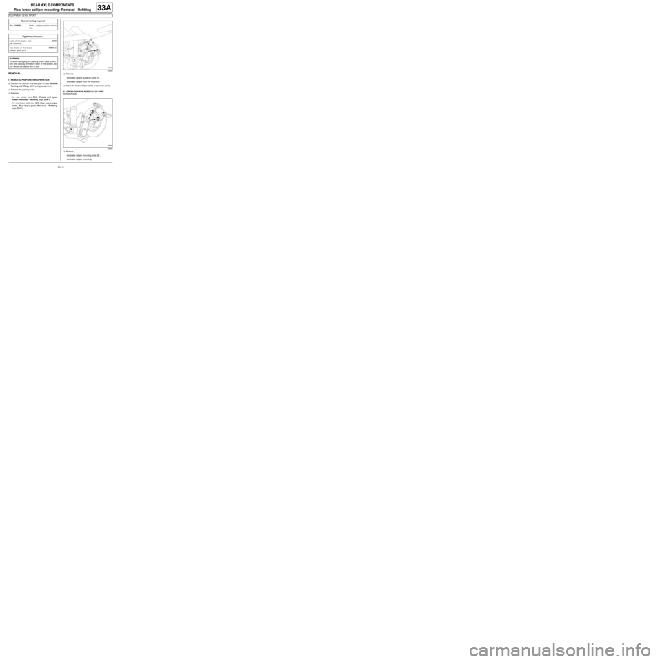
-the brake calliper guide pin bolts (1) ,
-the brake calliper from the mounting.
aAttach the brake calliper to the suspension spring.
II - OPERATION FOR REMOVAL OF PART
CONCERNED
aRemove:
-the brake calliper mounting bolts (2) ,
-the brake calliper mounting. Special tooling required
Fre. 1190-01Brake calliper piston return
tool.
Tightening torquesm
bolts of the brake calli-
per mountingXXX
new bolts of the brake
calliper guide pins105 N.m
WARNING
To avoid damaging the parking brake cable protec-
tors and causing premature wear of the system, do
not handle the cables with a tool.
132468
132465
Page 109 of 281

33A-11
REAR AXLE COMPONENTS
Rear brake disc: Removal - Refitting
EQ UIPMENT LEVEL SPORT
33A
Brake discs cannot be reground. If there is excessive
scoring or wear, they will need to be replaced (see
30A, General information, Brake: Specifications,
page 30A-19) .
REMOVAL
I - REMOVAL PREPARATION OPERATION
aPosition the vehicle on a two-post lift (see Vehicle:
Towing and lifting) (02A, Lifting equipment).
aRemove:
-the rear wheels (see 35A, Wheels and tyres,
Wheel: Removal - Refitting, page 35A-1) ,
-the rear brake pads (see 33A, Rear axle compo-
nents, Rear brake pads: Removal - Refitting,
page 33A-1) .aRemove:
-the brake calliper mounting bolts (1) ,
-the "brake calliper mounting - brake calliper" as-
sembly.
aAttach the "calliper mounting - brake calliper" to the
shock absorber spring.
II - OPERATION FOR REMOVAL OF PART
CONCERNED
aRemove the hub's nut cover (2) . Equipment required
par ts washer
Tightening torquesm
new hub nut175 N.m
brake calliper mounting
bolts105 N.m
WARNING
To avoid damaging the parking brake cable protec-
tors and causing premature wear of the system, do
not handle the cables with a tool.
132467
132456
Page 120 of 281
33A-22
REAR AXLE COMPONENTS
Rigid brake pipe: Removal - Refitting
C44
33A
The pipes have a rigid section and a flexible section.
REMOVAL
I - REMOVAL PREPARATION OPERATION
aPosition the vehicle on a two-post lift ( (see Vehicle:
Towing and lifting) ).
aFit the pedal press tool to the brake pedal to limit
the escape of brake fluid.II - OPERATION FOR REMOVAL OF PART
CONCERNED
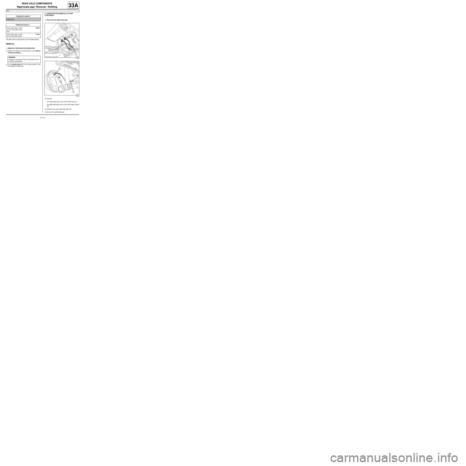
1 - Rear left-hand rigid brake pipe
aUnscrew:
-the rigid brake pipe union at the brake hose (1) .
-the rigid brake pipe union on the rear brake cylinder
(2) .
aUnclip the rear axle rigid brake pipe (3) .
aRemove the rigid brake pipe. Equipment required
pedal press
Tightening torquesm
rigid brake pipe unions
on the rear brake cylin-
ders15 Nm
rigid brake pipe unions
on the rear brake hoses17 Nm
WARNING
Prepare for the flow of fluid, and protect the sur-
rounding components.
119339
119337
Page 121 of 281
33A-23
REAR AXLE COMPONENTS
Rigid brake pipe: Removal - Refitting
C44
33A
2 - Rear right-hand rigid brake pipe
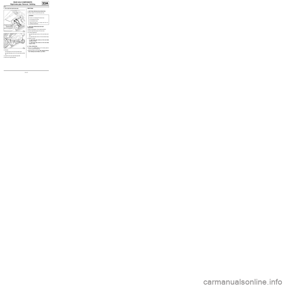
aUnscrew:
-the brake pipe union (4) at the brake hose,
-the rigid brake pipe union on the rear brake cylinder
(5) .
aUnclip the rear axle rigid brake pipe (6) .
aRemove the rigid brake pipe.REFITTING
I - REFITTING PREPARATION OPERATION
aAlways replace the rigid brake pipe clips.
II - REFITTING OPERATION FOR PART
CONCERNED
aRefit the rigid pipes in their original positions.
aClip the rigid brake pipes of the rear axle.
aFit without tightening:
-the rigid brake pipe unions on the rear brake cylin-
ders.
-the rigid brake pipe unions on the rear brake hoses.
aTighten to torque:
-the rigid brake pipe unions on the rear brake
cylinders (15 Nm),
-the rigid brake pipe unions on the rear brake
hoses (17 Nm),
III - FINAL OPERATION.
aRemove the pedal press from the brake pedal to
limit the outflow of brake fluid.
aBleed the brake circuit (see 30A, General informa-
tion, Braking circuit: Bleed, page 30A-4) .
119339
119338
WARNING
In order to not damage the brake hose:
-do not tension the hose,
-do not twist the hose,
-check that there is no contact with the sur-
rounding components.
Page 122 of 281
33A-24
REAR AXLE COMPONENTS
Shock absorber: Removal - Refitting
33A
If a shock absorber is replaced, the shock absorber on
the opposite side must also be replaced.
REMOVAL
I - REMOVAL PREPARATION OPERATION
aPosition the vehicle on a two-post lift (see Vehicle:
Towing and lifting) (MR 411, 02A, Lifting equip-
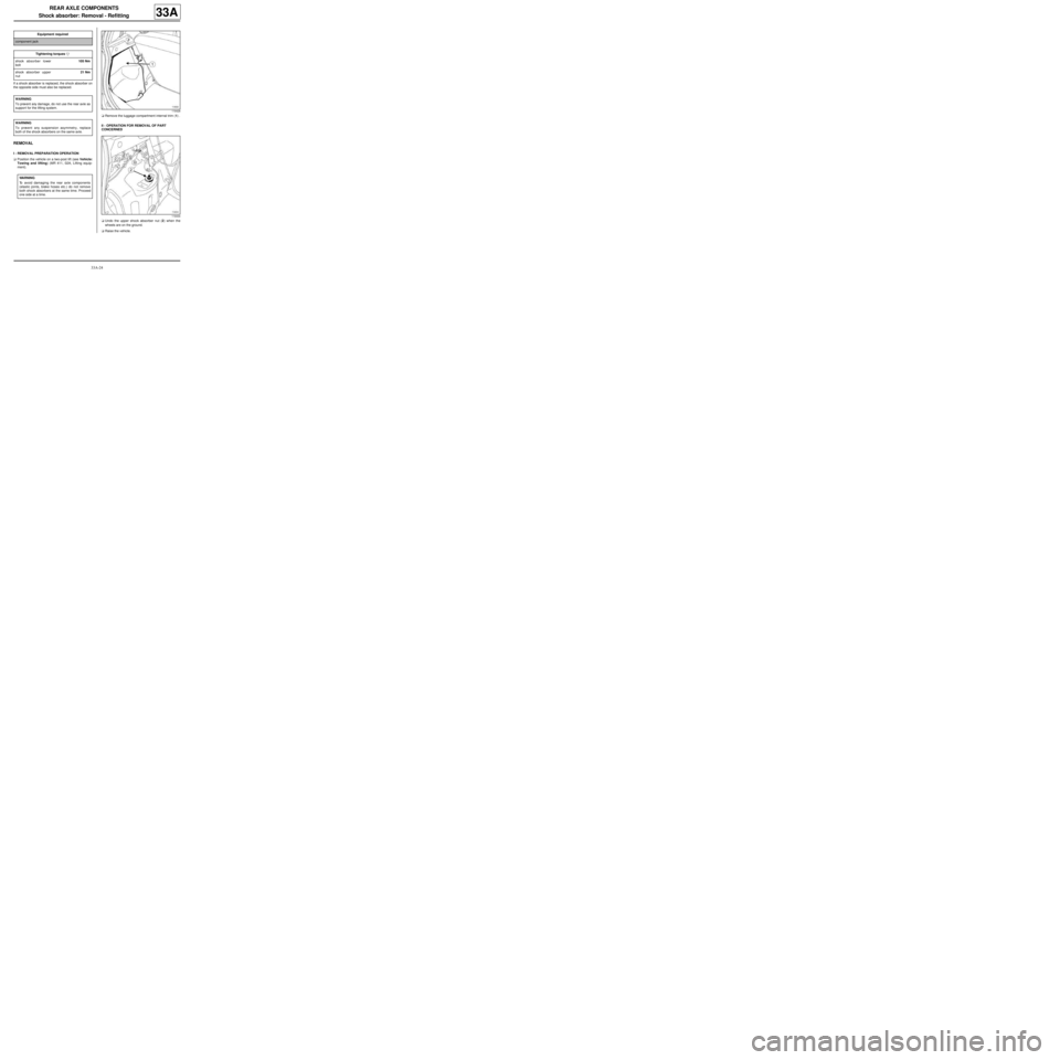
ment).aRemove the luggage compartment internal trim (1) .
II - OPERATION FOR REMOVAL OF PART
CONCERNED
aUndo the upper shock absorber nut (2) when the
wheels are on the ground.
aRaise the vehicle. Equipment required
component jack
Tightening torquesm
shock absorber lower
bolt105 Nm
shock absorber upper
nut21 Nm
WARNING
To prevent any damage, do not use the rear axle as
support for the lifting system.
WARNING
To prevent any suspension asymmetry, replace
both of the shock absorbers on the same axle.
WARNING
To avoid damaging the rear axle components
(elastic joints, brake hoses etc.) do not remove
both shock absorbers at the same time. Proceed
one side at a time.
119428
119434
Page 124 of 281
33A-26
REAR AXLE COMPONENTS
Shock absorber: Removal - Refitting
G44
33A
REMOVAL
I - REMOVAL PREPARATION OPERATION
aPosition the vehicle on a two-post lift (see Vehicle:
Towing and lifting) (MR 411, 02A, Lifting equip-
ment).
aRemove the luggage compartment interior trim (see
Rear loading trim: Removal - Refitting) (MR 412,
71A, Body internal trim).II - OPERATION FOR REMOVAL OF PART
CONCERNED
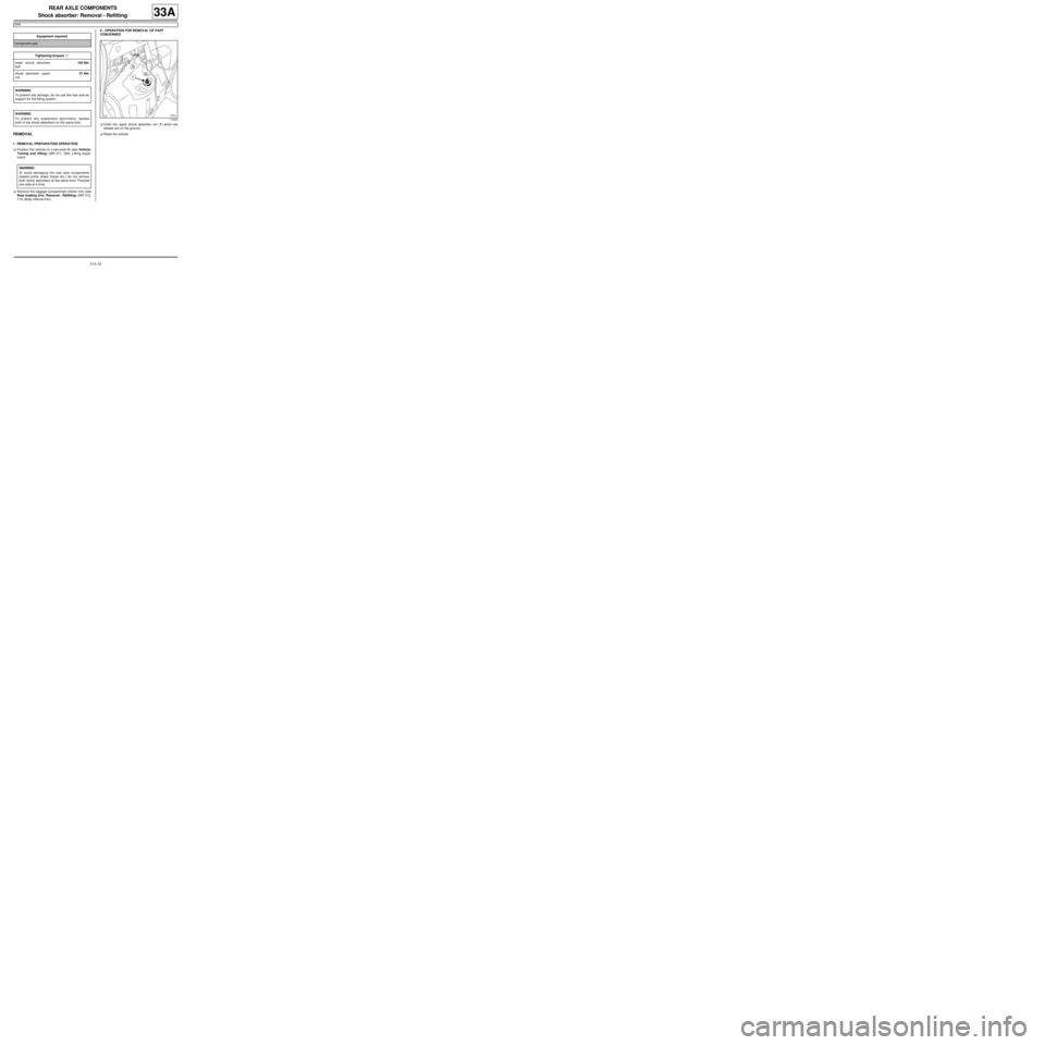
aUndo the upper shock absorber nut (1) when the
wheels are on the ground.
aRaise the vehicle. Equipment required
component jack
Tightening torquesm
lower shock absorber
bolt105 Nm
shock absorber upper
nut21 Nm
WARNING
To prevent any damage, do not use the rear axle as
support for the lifting system.
WARNING
To prevent any suspension asymmetry, replace
both of the shock absorbers on the same axle.
WARNING
To avoid damaging the rear axle components
(elastic joints, brake hoses etc.) do not remove
both shock absorbers at the same time. Proceed
one side at a time.
119434
Page 129 of 281
33A-31
REAR AXLE COMPONENTS
Rear drum bearing: Removal - Refitting
33A
REFITTING
I - REFITTING PREPARATIONS OPERATION
aClean:
-the internal and external surfaces of the new bear-
ing in contact with the drum,
-the drum surfaces in contact with the new bearing.
aIt is essential to check the condition of the surface of
the bore of the drum before refitting the bearing. It is
essential to replace the stub axle carrier if it is faulty.a
II - REFITTING OPERATION FOR PART
CONCERNED
aFit the bearing until it presses the shoulder using a
tube with a diameter between 51 mm and 54 mm
and using a hydraulic press.
aRefit the rubber ring.
III - FINAL OPERATION.
aRefit:
-the rear brake drum (see 33A, Rear axle compo-
nents, Rear brake drum: Removal - Refitting,
page 33A-19) ,
-the rear wheel (see 35A, Wheels and tyres,
Wheel: Removal - Refitting, page 35A-1) .
117348
WARNING
Do not press the bearing's inner bush so as to
avoid damaging the bearing (very high shrink-fit-
ting force).
121332
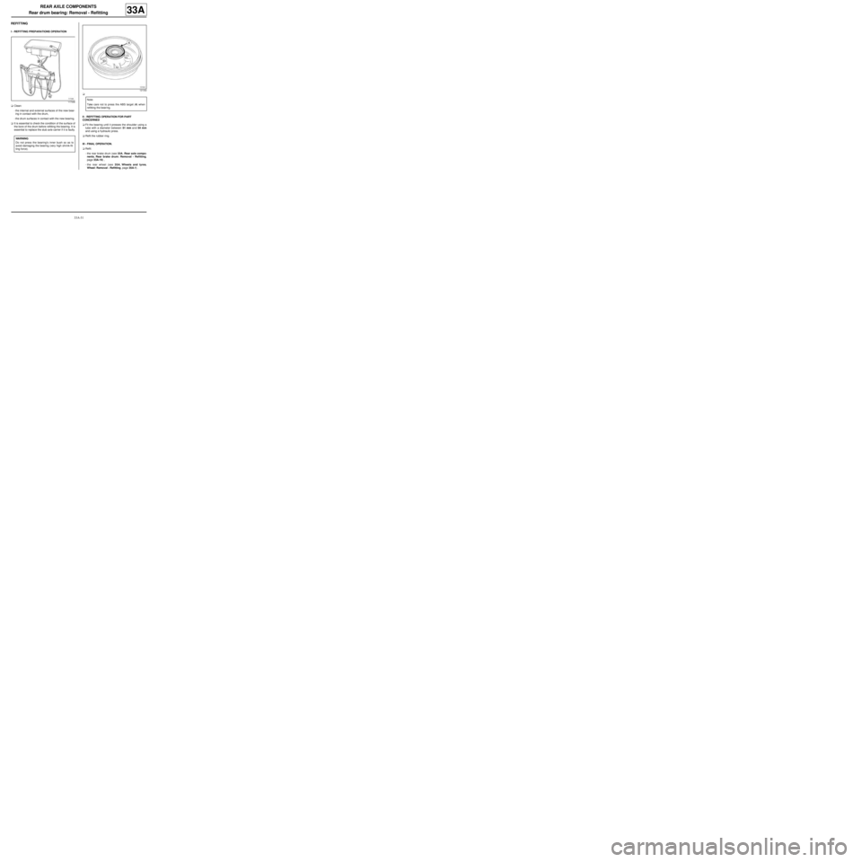
Note:
Take care not to press the ABS target (4) when
refitting the bear ing.
Page 132 of 281
33A-34
REAR AXLE COMPONENTS
Rear stub axle carrier: Removal - Refitting
EQ UIPMENT LEVEL SPORT
33A
REMOVAL
I - REMOVAL PREPARATION OPERATION
aPosition the vehicle on a two-post lift (see Vehicle:
Towing and lifting) (02A, Lifting equipment).
aRemove the rear wheel (see 35A, Wheels and ty-
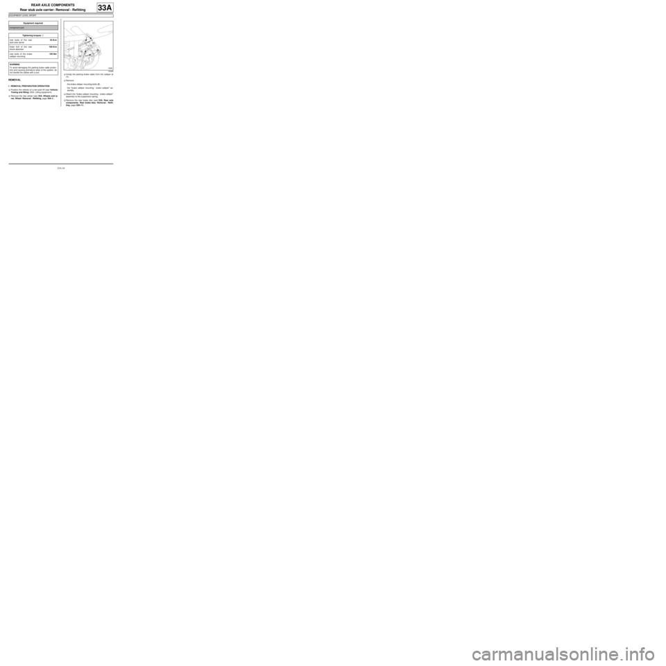
res, Wheel: Removal - Refitting, page 35A-1) .aUnclip the parking brake cable from the calliper at
(1) .
aRemove:
-the brake calliper mounting bolts (2) ,
-the "brake calliper mounting - brake calliper" as-
sembly.
aAttach the "brake calliper mounting - brake calliper"
assembly to the suspension spring.
aRemove the rear brake disc (see 33A, Rear axle
components, Rear brake disc: Removal - Refit-
ting, page 33A-11) . Equipment required
component jack
Tightening torquesm
new bolts of the rear
stub axle carrier53 N.m
lower bolt of the rear
shock absorber105 N.m
new bolts of the brake
calliper mounting105 Nm
WARNING
To avoid damaging the parking brake cable protec-
tors and causing premature wear of the system, do
not handle the cables with a tool.
132468
Page 146 of 281
35A-6
WHEELS AND TYRES
Wheel: Balancing
35A
aEnter the specific wheel parameters when starting
the wheel balancer.
aStart the wheel balancer and check the wheel bal-
ance, which should be 0 g on each plane of the
wheel.
aIf this is not the case, remove the old wheel balanc-
ing weights and repeat the wheel balancing proce-
dure, checking that the wheel balance equals 0 on
each wheel plane.
IV - FINAL OPERATION
aRefit the wheel (see 35A, Wheels and tyres,
Wheel: Removal - Refitting, page 35A-1) . WARNING
To avoid detachment of the balance weights, use
only weights which correspond to the vehicle
wheel rims.
Page 150 of 281
35A-10
WHEELS AND TYRES
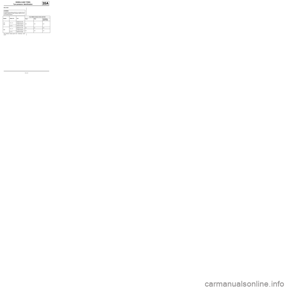
Tyre pressure: Identification
35A
INFLATION
The pressure values given are « motorway » pres-
sures.WARNING
If checking the pressure when hot, increase the tyre
inflation pressure by 0.2 to 0.3 bar above the rec-
ommended pressure.
Engine Wheel rim TyreTyre inflation pressure when cold (bar)
Front Rear emergency
spare wheel
D4F
D7F5.5 J 14165/65 R14 79T
2.2 2.0 2.2 175/65 R14 82 T
6 J 15 185/55 R15 82H
K9K5.5 J 14165/65 R14 79T 2.3 2.1 2.3
175/65 R14 82 T
2.2 2.0 2.2
6 J 15 185/55 R15 82H