warning RENAULT TWINGO RS 2009 2.G Chasiss Service Manual
[x] Cancel search | Manufacturer: RENAULT, Model Year: 2009, Model line: TWINGO RS, Model: RENAULT TWINGO RS 2009 2.GPages: 281
Page 158 of 281
36A-7
STEERING ASSEMBLY
Steering column: Removal - Refitting
LEFT-HAND DRIVE
36A
REMOVAL
I - REMOVAL PREPARATION OPERATION
aUnlock the steering column.
aLock the airbag computer using the Diagnostic tool
(see Fault finding - Replacement of components)
(MR 413, 88C, Airbags - Pretensioners).
aDisconnect the battery (see Battery: Removal - Re-
fitting) (MR 411, 80A, Battery).
aSet the wheels straight ahead.
aRemove:
-the driver's front airbag (see Driver's frontal air-
bag: Removal - Refitting) (MR 411, 88C, Airbags
- Pretensioners),
-the steering wheel (see 36A, Steering assembly,
Steering wheel: Removal - Refitting, page 36A-
23) ,-the steering column switch assembly (see Steer-
ing column switch assembly: Removal - Refit-
ting) (MR 411, 84A, Steering column switch
assembly),
-the immobiliser antenna/transponder ring (see
Transponder ring: Removal - Refitting) (MR
411, 82A, Immobiliser),
-the ignition switch if the steering column is replaced
(see Ignition switch: Removal - Refitting) (MR
411, 82A, Immobiliser).
II - REMOVAL OPERATION FOR PART
CONCERNED
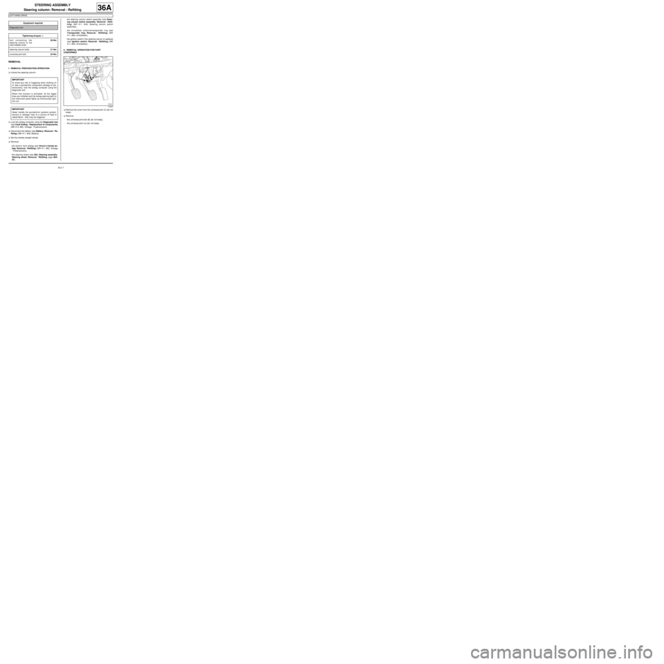
aRemove the cover from the universal joint (1) (do not
keep).
aRemove:
-the universal joint bolt (2) (do not keep),
-the universal joint nut (do not keep). Equipment required
Diagnostic tool
Tightening torquesm
bolt connecting the
steering column to the
inter mediate shaft30 Nm
steer ing column bolts21 Nm
universal joint bolt24 Nm
IMPORTANT
To avoid any risk of triggering when working on
or near a pyrotechnic component (airbags or pre-
tensioners), lock the airbag computer using the
diagnostic tool.
When this function is activated, all the trigger
lines are inhibited and the airbag warning light on
the instrument panel lights up continuously (igni-
tion on).
IMPORTANT
Never handle the pyrotechnic systems (preten-
sioners or airbags) near to a source of heat or
naked flame - they may be triggered.
119544
Page 162 of 281
36A-11
STEERING ASSEMBLY
Steering column: Removal - Refitting
RIGHT-HAND DRIVE
36A
REMOVAL
I - REMOVAL PREPARATION OPERATION
aUnlock the steering column.
a
Lock the airbag computer using the Diagnostic tool
(see Fault finding - Replacement of components)
(MR 413, 88C, Airbags and seat belt pretensioners).
aDisconnect the battery (see Battery: Removal - Re-
fitting) (MR 411, 80A, Battery).
aRemove:
-the driver's front airbag (see Driver's frontal air-
bag: Removal - Refitting) (MR 411, 88C, Airbags
and pretensioners),
-the steering wheel (see 36A, Steering assembly,
Steering wheel: Removal - Refitting, page 36A-
23) .aRemove the rev counter (see Rev counter: Remov-
al - Refitting) (MR 411, 83A, Instrument panel).
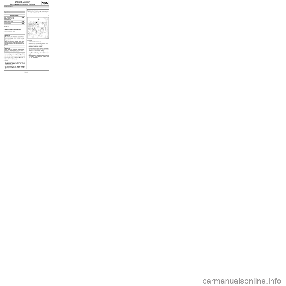
aRemove:
-the dashboard lower cover (1) ,
-the bolts (2) from the steering wheel lower cover,
-the steering wheel lower cover (3) ,
-the steering wheel upper cover (4) ,
-the steering column switch assembly (see Steer-
ing column switch assembly: Removal - Refit-
ting) (MR 411, 84A, Control - Signals),
-the antenna/transponder ring (see Transponder
ring: Removal - Refitting) (MR 411, 82A, Immobi-
liser),
-the ignition switch if the steering column is replaced
(see Ignition switch: Removal - Refitting) (MR
411, 82A, Immobiliser). Equipment required
Diagnostic tool
Tightening torquesm
bolt connecting the
steer ing column and the
inter mediate shaft30 Nm
steer ing column bolts21 Nm
universal joint bolt24 Nm
IMPORTANT
To avoid any risk of triggering when working on
or near a pyrotechnic component (airbags or pre-
tensioners), lock the airbag computer using the
diagnostic tool.
When this function is activated, all the trigger
lines are inhibited and the airbag warning light on
the instrument panel lights up continuously (igni-
tion on).
IMPORTANT
Never handle the pyrotechnic systems (preten-
sioners or airbags) near to a source of heat or
naked flame - they may be triggered.
ENGINE REV COUNTER
123870
Page 174 of 281
36A-23
STEERING ASSEMBLY
Steering wheel: Removal - Refitting
36A
REMOVAL
I - REMOVAL PREPARATION OPERATION
aApply the procedure for deactivating the safety sys-
tems. (see Airbag and pretensioners: Precau-
tions for the repair)
a
aRemove the driver's front airbag (see Driver's fron-
tal airbag: Removal - Refitting) .
aSet the wheels straight ahead.
aDisconnect the connectors.II - OPERATION FOR REMOVAL OF PART
CONCERNED
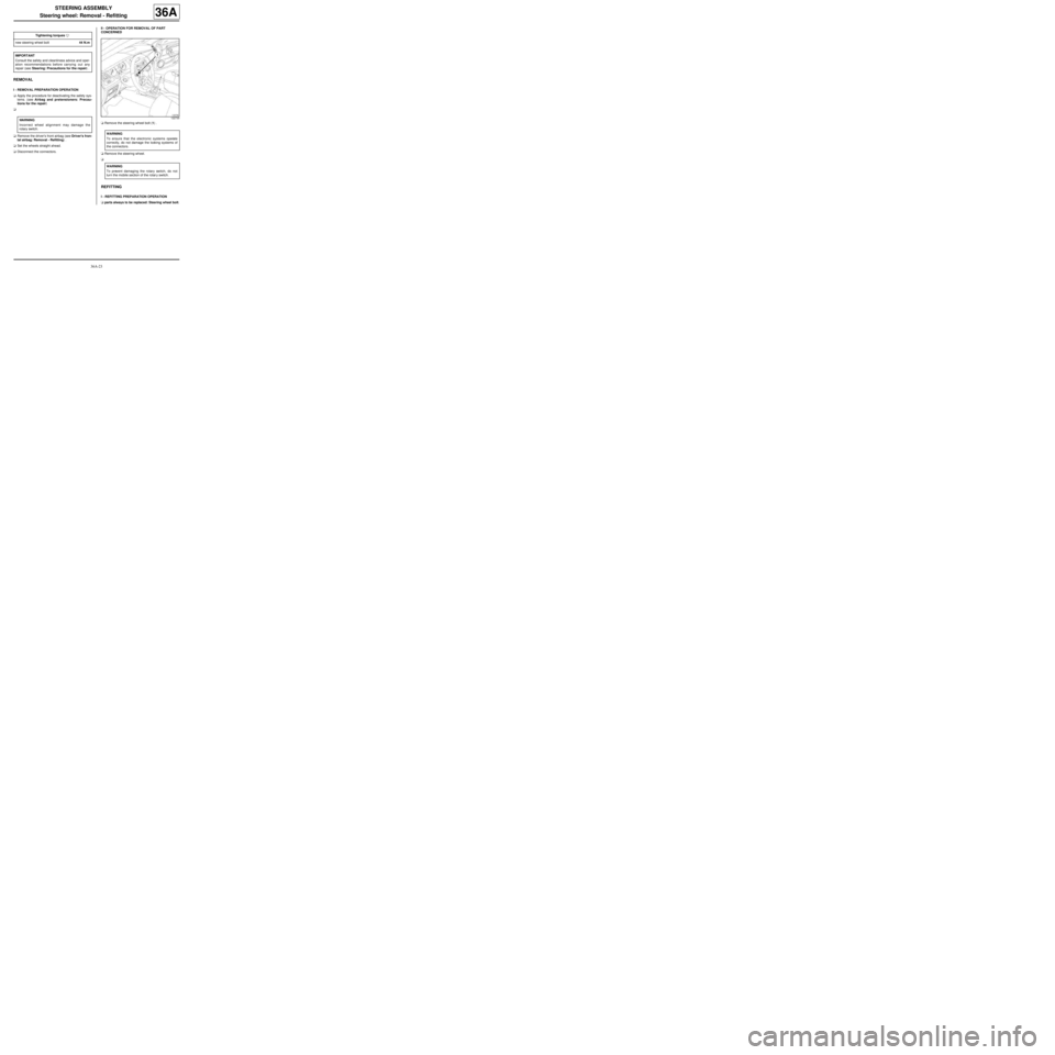
aRemove the steering wheel bolt (1) .
aRemove the steering wheel.
a
REFITTING
I - REFITTING PREPARATION OPERATION
aparts always to be replaced: Steering wheel bolt. Tightening torquesm
new steering wheel bolt44 N.m
IMPORTANT
Consult the safety and cleanliness advice and oper-
ation recommendations before carrying out any
repair (see Steering: Precautions for the repair) .
WARNING
Incorrect wheel alignment may damage the
rotary switch.
122730
WARNING
To ensure that the electronic systems operate
correctly, do not damage the locking systems of
the connectors.
WARNING
To prevent damaging the rotary switch, do not
turn the mobile section of the rotar y switch.
Page 175 of 281
36A-24
STEERING ASSEMBLY
Steering wheel: Removal - Refitting
36A
II - REFITTING OPERATION FOR PART
CONCERNED
a
aRefit the steering wheel.
aConnect the connectors.
aRefit the new steering wheel bolt.
aTorque tighten the new steering wheel bolt (44
N.m).
III - FINAL OPERATION
aRefit the driver's front airbag (see Driver's frontal
airbag: Removal - Refitting) .
IV - CHECKING AFTER REPAIR
aSwitch on the ignition.
aCheck the operation of the rotary switch:
-turn the steering wheel to the left until it stops,
-turn the steering wheel to the right until it stops,
-check that there are no faults on the instrument
panel.
105327
WARNING
In order not to damage the steering wheel or
steering column, the steering wheel-column fool-
proofing devices must be aligned.
Page 180 of 281
37A-1
MECHANICAL COMPONENT CONTROLS
Master cylinder: Removal - Refitting
JB1 or JH1 or JH3 or JR5
37A
REMOVAL
I - REMOVAL PREPARATION OPERATION
aPosition the vehicle on a two-post lift (see Vehicle:
Towing and lifting) (02A, Lifting equipment).
aRemove:
-the battery (see Battery: Removal - Refitting)
(80A, Battery)
-the battery tray (see Battery tray: Removal - Re-
fitting) (80A, Battery).
aRemove:
-the injection computer (see Petrol injection com-
puter: Removal - Refitting) (17B, Petrol injection),
-the injection computer support.II - OPERATION FOR REMOVAL OF PART
CONCERNED
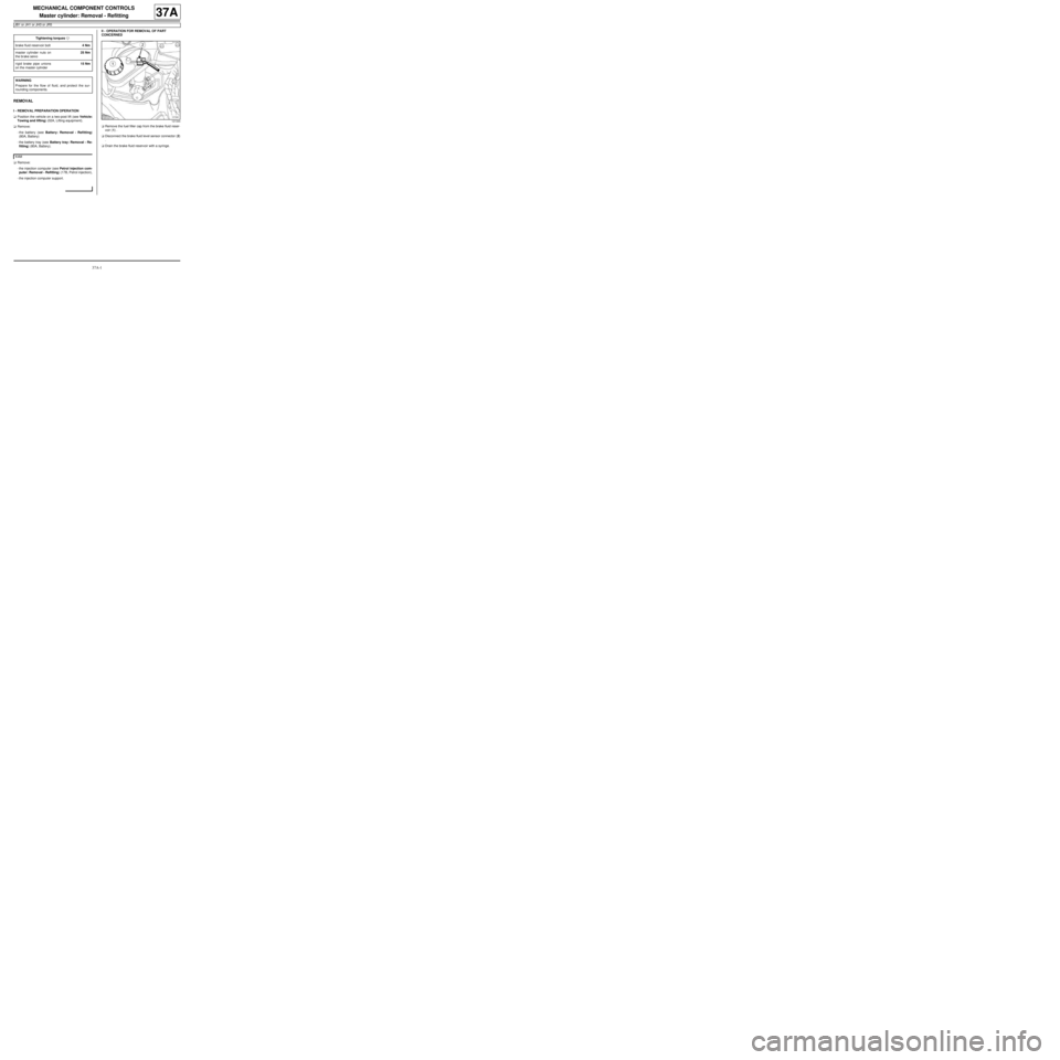
aRemove the fuel filler cap from the brake fluid reser-
voir (1) .
aDisconnect the brake fluid level sensor connector (2)
.
aDrain the brake fluid reservoir with a syringe. Tightening torquesm
brake fluid reservoir bolt4 Nm
master cylinder nuts on
the brake servo25 Nm
rigid brake pipe unions
on the master cylinder15 Nm
WARNING
Prepare for the flow of fluid, and protect the sur-
rounding components.
K4M
121344
Page 184 of 281
37A-5
MECHANICAL COMPONENT CONTROLS
Master cylinder: Removal - Refitting
RIGHT-HAND DRIVE
37A
REMOVAL
I - REMOVAL PREPARATION OPERATION
aPosition the vehicle on a two-post lift (see Vehicle:
Towing and lifting) (02A, Lifting equipment).
aRemove:
-the scuttle panel grille (see Scuttle panel grille:
Removal - Refitting) (56A, Exterior equipment),
-the scoop under the scuttle panel grille (see Scoop
under the scuttle panel grille: Removal - Refit-
ting) (56A, Exterior equipment).aRemove:
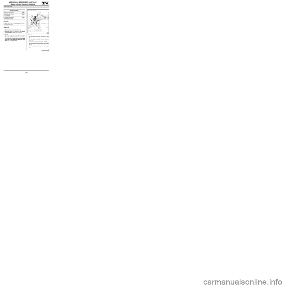
-the fuel vapour recirculation solenoid valve pipes
(1) ,
-the fuel vapour recirculation solenoid valve con-
nector (2) ,
-the fuel vapour recirculation solenoid valve (3) ,
-the fuel vapour recirculation solenoid valve support
nut (4) ,
-the fuel vapour recirculation solenoid valve support
(5) . Tightening torquesm
brake fluid reservoir bolt4 Nm
master cylinder bolts on
the brake servo25 Nm
rigid brake pipe unions
on the master cylinder15 Nm
WARNING
Prepare for the flow of fluid, and protect the sur-
rounding components.
D4F or D7F or K4M
123852
Page 204 of 281
37A-25
MECHANICAL COMPONENT CONTROLS
Vacuum pump: Removal - Refitting
K9K
37A
REMOVAL
I - REMOVAL PREPARATION OPERATION
aRemove:
-the engine cover,
-the air filter unit (see Air filter unit: Removal - Re-
fitting) (MR 411, 12A, Fuel mixture).
II - OPERATION FOR REMOVAL OF PART
CONCERNED
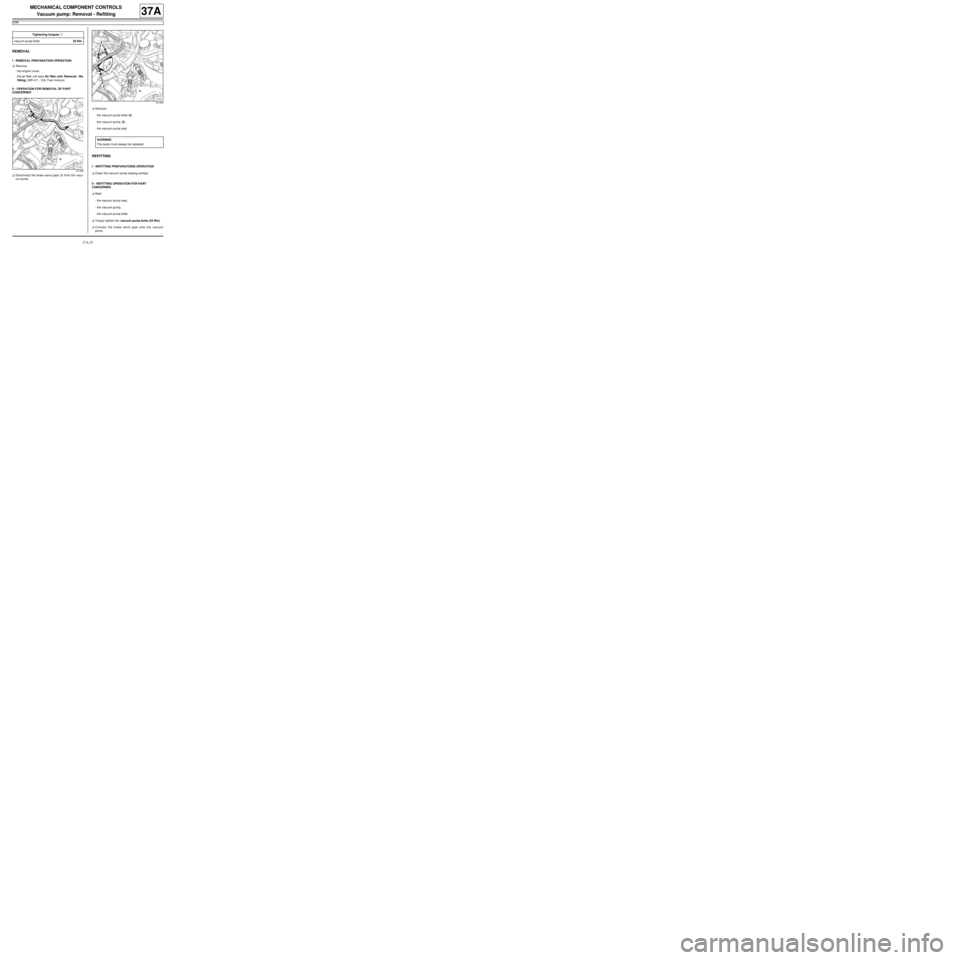
aDisconnect the brake servo pipe (1) from the vacu-
um pump.aRemove:
-the vacuum pump bolts (2) ,
-the vacuum pump (3) ,
-the vacuum pump seal.
REFITTING
I - REFITTING PREPARATIONS OPERATION
aClean the vacuum pump sealing surface.
II - REFITTING OPERATION FOR PART
CONCERNED
aRefit:
-the vacuum pump seal,
-the vacuum pump,
-the vacuum pump bolts.
aTorque tighten the vacuum pump bolts (25 Nm).
aConnect the brake servo pipe onto the vacuum
pump. Tightening torquesm
vacuum pump bolts25 Nm
121356
121355
WARNING
The seals m ust always be replaced.
Page 221 of 281
37A-42
MECHANICAL COMPONENT CONTROLS
Brake pedal switch: Removal - Refitting
37A
REMOVAL
I - REMOVAL PREPARATION OPERATION
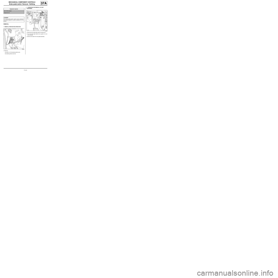
aRemove:
-the bolts (1) of the steering wheel cover,
-the steering wheel cover (2) .II - OPERATION FOR REMOVAL OF PART
CONCERNED
aDisconnect the brake light switch connector (3) .
aTurn the brake light switch (4) a quarter of a turn
anti-clockwise.
aRemove the switch from the pedal assembly. Equipment required
set of feeler gauges
Diagnostic tool
WARNING
The brake pedal position switch must be replaced if
the notched segment is pulled completely out of the
switch.
120279
121350
Page 222 of 281
37A-43
MECHANICAL COMPONENT CONTROLS
Brake pedal switch: Removal - Refitting
37A
REFITTING
I - REFITTING PREPARATION OPERATION
a
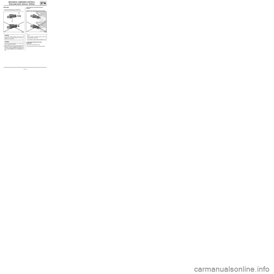
aMeasure dimension X of the notched segment (5) . If
dimension X is less than 28 mm, pull carefully on the
end of the notched segment (5) to adjust the dimen-
sion X between 28 mm minimum and 29 mm maxi-
mum.Visual inspection of the switch during the
operation
Position of the notched segment and the flange
a
II - REFITTING OPERATION FOR PART
CONCERNED
aDepress the brake pedal by hand.
aFit the brake light switch to the pedal assembly.
134304
WARNING
The brake pedal position switch must be
replaced if the notched segment is pulled com-
pletely out of the switch.
WARNING
The switch must be replaced if the notched seg-
ment is adjusted three times.
134305
Note:
With the pedal in the highest position, check that
the flange (8) is not visible.
If the flange is visible, repeat the adjustment of X.
Page 232 of 281
37A-53
MECHANICAL COMPONENT CONTROLS
Clutch pedal switch: Removal - Refitting
CRUISE CONTROL, and 5-SPEED MANUAL GEARBOX
37A
REFITTING
I - REFITTING PREPARATIONS OPERATION
a
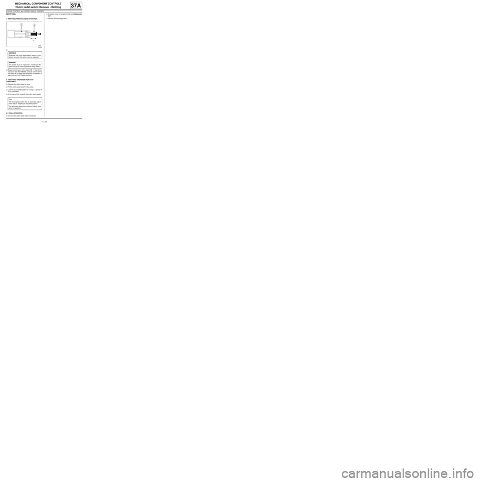
aMeasure dimension of the piston (4) . If the dimen-
sion (x) is less than 15 mm, carefully pull the end of
the piston (4) to adjust the dimension to between 15
mm minimum and 17 mm maximum.
II - REFITTING OPERATION FOR PART
CONCERNED
aDepress the clutch pedal by hand.
aFit the clutch pedal switch to the pedal.
aLock the clutch pedal switch by turning it a quarter of
a turn clockwise.
aAt the same time, carefully return the clutch pedal.
III - FINAL OPERATION.
aConnect the clutch pedal switch connector.aBe sure to carry out a repair check using Diagnostic
tool.
aRefit the dashboard glovebox.
108436
WARNING
Whenever the clutch pedal switch piston is com-
pletely removed, the switch must be replaced.
WARNING
The switch must be replaced if handling of the
piston results in three adjustments being made.
Note:
The clutch pedal switch has an automatic adjust-
ment feature, adapting to the pedal position.
The automatic adjustment makes a clicking noise
when in operation.