ignition RENAULT TWINGO RS 2009 2.G Electrical Equipment - Access Safety Workshop Manual
[x] Cancel search | Manufacturer: RENAULT, Model Year: 2009, Model line: TWINGO RS, Model: RENAULT TWINGO RS 2009 2.GPages: 43, PDF Size: 0.2 MB
Page 2 of 43

82D-2
MR-413-X44-82D000$100_eng.mif
V1
82D
ACCESS/SAFETY
Fault finding - Introduction
1. SCOPE OF THIS DOCUMENT
This document presents the fault finding procedure applicable to all computers with the following specifications:
2. PREREQUISITES FOR FAULT FINDING
Documentation type
Fault finding procedures (this manual):
–Assisted fault finding (integrated into the diagnostic tool), Dialogys.
Wiring Diagrams:
–Visu-Schéma (CD-ROM), paper.
Type of diagnostic tools
–CLIP
Special tooling required
3. REMINDERS
To run fault finding on the vehicle's computers, switch on the ignition in fault finding mode (+ after ignition feed).Vehicle(s): New TWINGO
Function concerned: Access/Safety
Special tooling required
Multimeter
Elé. 1681 Universal bornier
MR-413-X44-82D000$100_eng.mif
Page 3 of 43

82D-3
MR-413-X44-82D000$100_eng.mif
V1
ACCESS/SAFETY
Fault finding - Introduction82D
Faults
Faults are declared as either present or stored (depending on whether they appeared in a certain context and have
disappeared since, or whether they remain present but have not been diagnosed within the current context).
The present or stored status of faults should be taken into consideration when the diagnostic tool is switched on
after the + after ignition feed (without any system components being active).
For a present fault, apply the procedure described in the Interpretation of faults section.
For a stored fault, note the faults displayed and apply the instructions in the Notes section.
If the fault is confirmed when the instructions in the Notes section are applied, the fault is present. Deal with the fault
If the fault is not confirmed, check:
–the electrical lines which correspond to the fault,
–the connectors on these lines (corrosion, bent pins, etc.),
–the resistance of the component detected as faulty,
–the condition of the wires (melted or split insulation, wear).
Conformity check
The aim of the conformity check is to check data that does not produce a fault on the diagnostic tool because the
data is inconsistent. Therefore, this stage is used to:
–carry out fault finding on faults that do not have a fault display, and which may correspond to a customer
complaint.
–check that the system is operating correctly and that there is no risk of a fault recurring after repairs.
This section gives the fault finding procedures for statuses and parameters and the conditions for checking them.
If a status is not behaving normally or a parameter is outside the permitted tolerance values, consult the
corresponding fault finding page.
Customer complaints - Fault finding chart
If the test with the diagnostic tool is OK but the customer complaint is still present, the fault should be processed by
customer complaints.
A summary of the overall procedure to follow is provided on the following page in the
form of a flow chart.
Page 6 of 43

82D-6
MR-413-X44-82D000$100_eng.mif
V1
ACCESS/SAFETY
Fault finding - Introduction82D
5. FAULT FINDING LOG
You will always be asked for this log:
–when requesting technical assistance from the Techline,
–for approval requests when replacing parts for which approval is obligatory
–to be attached to monitored parts for which reimbursement is requested. The log is needed for warranty
reimbursement, and enables better analysis of the parts removed.
6. SAFETY INSTRUCTIONS
All work on components requires the observation of safety rules to prevent damage or injury:
–check the battery voltage to avoid incorrect operation of computer functions,
–Use the proper tools.
Procedure for disconnecting the battery:
–switch off the ignition,
–switch off all consumers,
–wait at least 1 minute for the electronic systems to switch off,
–disconnect the battery, starting with the negative terminal. IMPORTANTIMPORTANT
Any fault on a complex system requires thorough fault finding with the appropriate tools. The
FAULT FINDING LOG, which should be completed during the procedure, enables you to keep
track of the procedure which is carried out. It is an essential document when consulting the
manufacturer.
IT IS THEREFORE MANDATORY TO FILL OUT A FAULT FINDING LOG EACH TIME FAULT FINDING IS
CARRIED OUT.
Page 15 of 43
82D-15
MR-413-X44-82D000$500_eng.mif
V1
ACCESS/SAFETY
Fault finding - Function82D
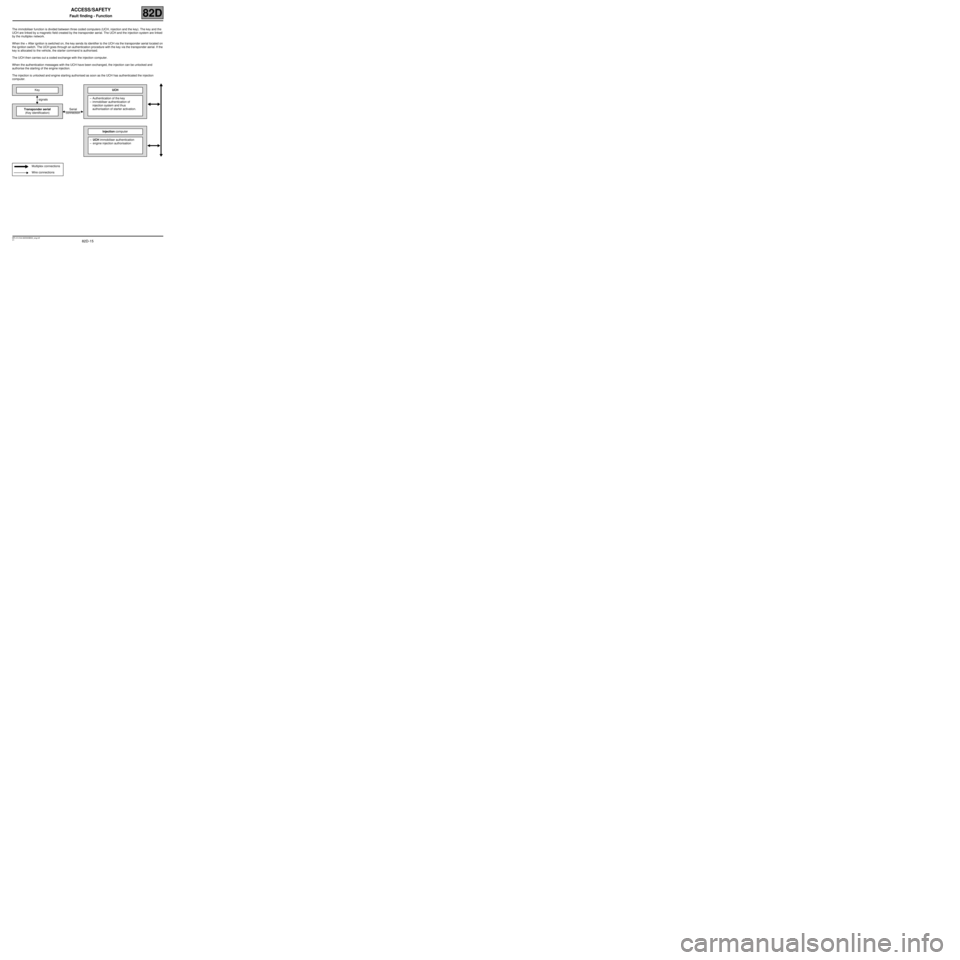
The immobiliser function is divided between three coded computers (UCH, injection and the key). The key and the
UCH are linked by a magnetic field created by the transponder aerial. The UCH and the injection system are linked
by the multiplex network.
When the + After ignition is switched on, the key sends its identifier to the UCH via the transponder aerial located on
the ignition switch. The UCH goes through an authentication procedure with the key via the transponder aerial. If the
key is allocated to the vehicle, the starter command is authorised.
The UCH then carries out a coded exchange with the injection computer.
When the authentication messages with the UCH have been exchanged, the injection can be unlocked and
authorise the starting of the engine injection.
The injection is unlocked and engine starting authorised as soon as the UCH has authenticated the injection
computer.
KeyUCH
signals–Authentication of the key
–immobiliser authentication of
injection system and thus
authorisation of starter activation.
Transponder aerial
(Key identification)Serial
connection
Injection computer
–UCH immobiliser authentication
–engine injection authorisation
Multiplex connections
Wire connections
Page 18 of 43
82D-18
MR-413-X44-82D000$500_eng.mif
V1
ACCESS/SAFETY
Fault finding - Function82D
2. Protection
PROCESS FOR REMOVING VEHICLE PROTECTION
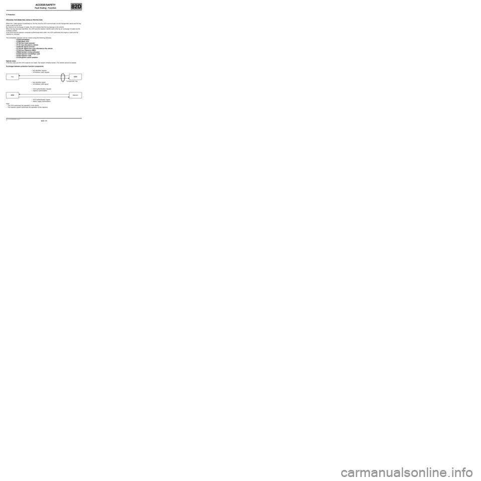
When the + after ignition is switched on, the key and the UCH communicate via the transponder aerial and the key
code is sent to the UCH.
By means of an exchange of codes, the UCH checks that the key belongs to the vehicle.
When the key has been identified, the UCH and the injection identify each other by an exchange of codes via the
multiplex system.
If the UCH and the injection computer authenticate each other, the UCH authorises the engine to start and the
injection is unlocked.
The immobiliser statuses can be viewed using the following statuses:
–ET046 Immobiliser
–ET008 Blank UCH
–ET185 Key Code received
–ET181 Key allocated to vehicle
–ET045 RF signal received
–ET193 RF signal from a key allocated to the vehicle
–ET240 Key frequency (MHz)
–PR056 Number of keys allocated
–ET229 Injection immobiliser code
–ET250 Injection code
–ET239 Ignition switch position
Special cases
If the key code and the UCH code do not match, the system remains locked. The vehicle cannot be started.
Exchanges between protection function components
Note:
–The UCH authorises the operation of the starter.
–The injection system authorises the operation of the injectors.–key identifier request
–immobiliser code request
KeyUCH
Transponder ring
–key identifier signal
–immobiliser code signal
–UCH authentication request
–injection authorisation
UCHInjection
–UCH authentication signal
–starter supply authorisation
Page 19 of 43

82D-19
MR-413-X44-82D000$500_eng.mif
V1
ACCESS/SAFETY
Fault finding - Function82D
3. Starting
The UCH controls the command and supply part of the start-up function while the start-up-charging process is
controlled by the UCH. For this function to operate normally, the protection function must have been successfully
completed.
To enable the starting command the UCH needs information about the following statuses and parameters:
–ET142 Engine operating phase
–ET239 Ignition switch position
–PR025 "Engine speed"
*Powerlatch: Time required for injection computer supply after + 12 V APC cut-off to the ignition switch.
Extended memory key:
In this case, the UCH sends data to the key at specific times to provide the key with up-to-date application data when
the + after ignition feed is cut off.
The following information can be retrieved on the multiplex line:
–The vehicle identification number.
–If entered by customer services: the customer's contact details.
–The total vehicle mileage.
–The fuel level.
–The mileage before oil service.
The UCH sends this information to the key under the following conditions:
–Every time the vehicle is started.
–Every time the vehicle speed drops below 3 mph (5 km/h) and if 1 mile (2 km) have been travelled since the last
record. IMPORTANT
When the vehicle battery has a low charge, the drop in voltage caused by operating the starter could reactivate
the immobiliser. If the voltage is too low, the engine cannot be started, even by pushing the vehicle.
Note:
If several, i.e. three or four, attempts have been made using a key not allocated to the vehicle, the injection
computer locks. Insert a key allocated to the vehicle for 20 seconds in + after ignition feed, then switch off the
ignition and wait for the end of "powerlatch*" (20 minutes) to allow the injection computer to unlock.
Page 21 of 43
82D-21
MR-413-X44-82D000$700_eng.mif
V1
82D
ACCESS/SAFETY
Fault finding - Conformity check
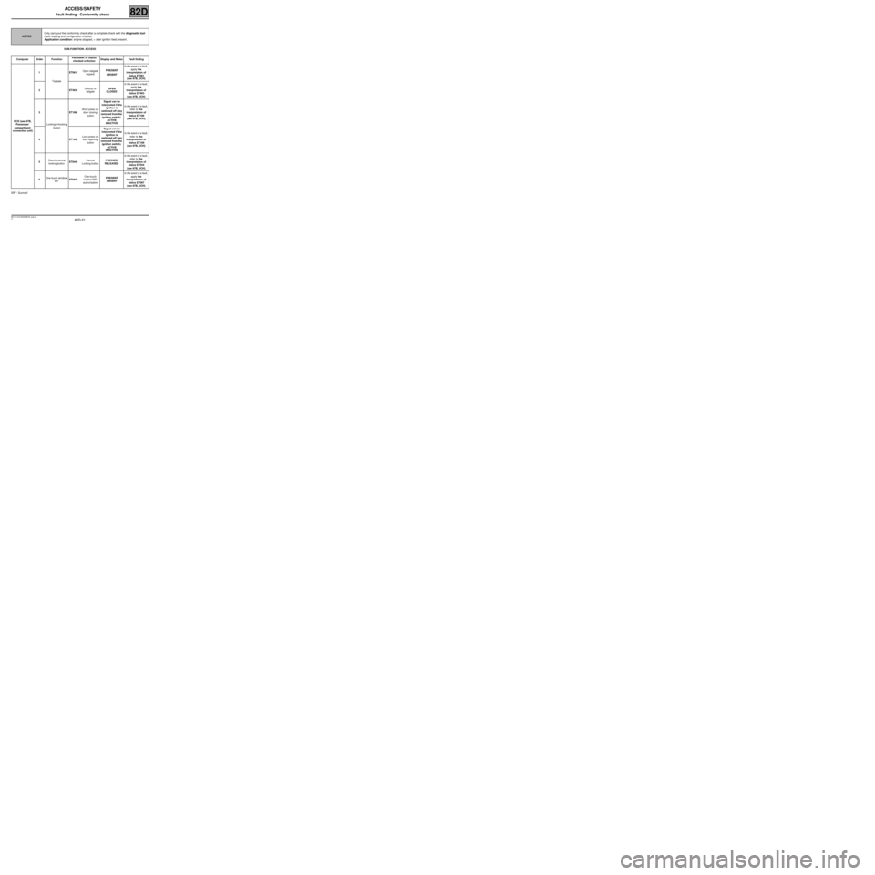
SUB-FUNCTION: ACCESS
SR.*: Sunroof
NOTESOnly carry out this conformity check after a complete check with the diagnostic tool
(fault reading and configuration checks).
Application condition: engine stopped, + after ignition feed present.
Computer Order FunctionParameter or Status
checked or ActionDisplay and Notes Fault finding
UCH (see 87B,
Passenger
compartment
connection unit)1
TailgateET061:Open tailgate
requestPRESENT
ABSENTIn the event of a fault,
apply the
interpretation of
status ET061
(see 87B, UCH).
2ET463:Door(s) or
tailgateOPEN
CLOSEDIn the event of a fault,
apply the
interpretation of
status ET463
(see 87B, UCH).
3
Locking/unlocking
buttonET186:Short press on
door closing
buttonSignal can be
interpreted if the
ignition is
switched off (key
removed from the
ignition switch).
ACTIVE
INACTIVEIn the event of a fault,
refer to the
interpretation of
status ET186
(see 87B, UCH).
4ET189:Long press on
door opening
buttonSignal can be
interpreted if the
ignition is
switched off (key
removed from the
ignition switch).
ACTIVE
INACTIVEIn the event of a fault,
refer to the
interpretation of
status ET189
(see 87B, UCH).
5Electric central
locking buttonET044:Central
Locking buttonPRESSED
RELEASEDIn the event of a fault,
refer to the
interpretation of
status ET044
(see 87B, UCH).
6One-touch window/
SR*ET087:One-touch
window/SR*
authorisationPRESENT
ABSENTIn the event of a fault,
apply the
interpretation of
status ET087
(see 87B, UCH).
MR-413-X44-82D000$700_eng.mif
Page 22 of 43
82D-22
MR-413-X44-82D000$700_eng.mif
V1
ACCESS/SAFETY
Fault finding - Conformity check82D
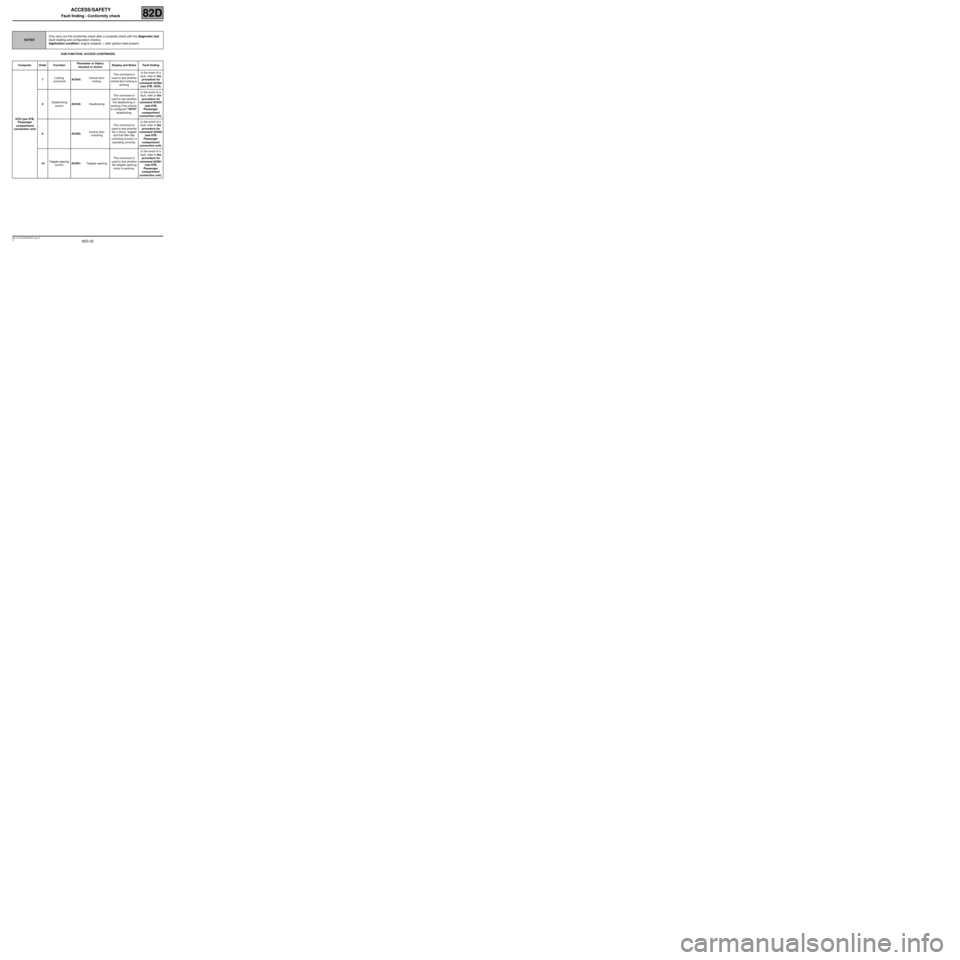
SUB-FUNCTION: ACCESS (CONTINUED)
NOTESOnly carry out this conformity check after a complete check with the diagnostic tool
(fault reading and configuration checks).
Application condition: engine stopped, + after ignition feed present.
Computer Order FunctionParameter or Status
checked or ActionDisplay and Notes Fault finding
UCH (see 87B,
Passenger
compartment
connection unit)7Locking
commandAC004:Central door
lockingThis command is
used to test whether
central door locking is
workingIn the event of a
fault, refer to the
procedure for
command AC004
(see 87B, UCH).
8Deadlocking
controlAC035:DeadlockingThis command is
used to test whether
the deadlocking is
working if the vehicle
is configured "WITH"
deadlocking.In the event of a
fault, refer to the
procedure for
command AC035
(see 87B,
Passenger
compartment
connection unit).
9AC005:Central door
unlockingThis command is
used to test whether
the 4 doors, tailgate
and fuel filler flap
unlocking function is
operating correctly.In the event of a
fault, refer to the
procedure for
command AC005
(see 87B,
Passenger
compartment
connection unit).
10Tailgate opening
controlAC061:Tailgate openingThis command is
used to test whether
the tailgate opening
motor is working.In the event of a
fault, refer to the
procedure for
command AC061
(see 87B,
Passenger
compartment
connection unit).
Page 23 of 43
82D-23
MR-413-X44-82D000$700_eng.mif
V1
ACCESS/SAFETY
Fault finding - Conformity check82D
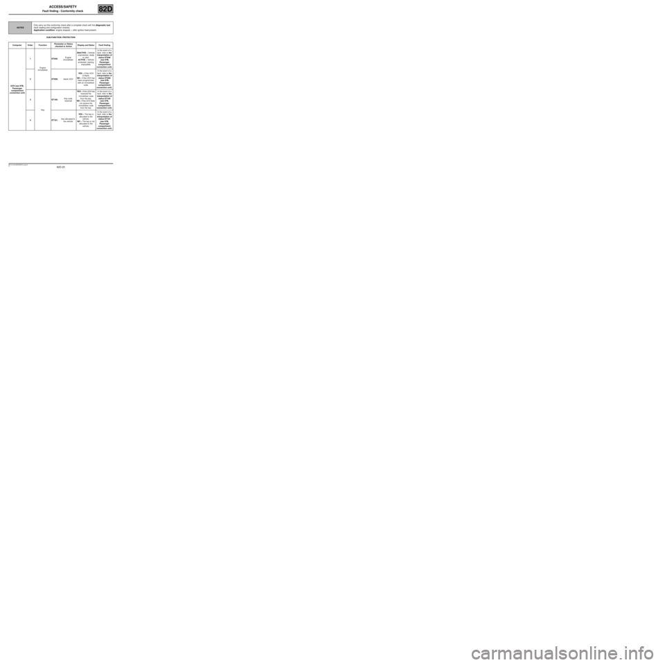
SUB-FUNCTION: PROTECTION
NOTESOnly carry out this conformity check after a complete check with the diagnostic tool
(fault reading and configuration checks).
Application condition: engine stopped, + after ignition feed present.
Computer Order FunctionParameter or Status
checked or ActionDisplay and Notes Fault finding
UCH (see 87B,
Passenger
compartment
connection unit)1
Engine
immobiliserET046:Engine
immobiliserINACTIVE = Vehicle
unprotected, ready
to start.
ACTIVE = Vehicle
protected, starting
impossible.In the event of a
fault, refer to the
interpretation of
status ET046
(see 87B,
Passenger
compartment
connection unit).
2ET008:blank UCHYES = If the UCH
is blank.
NO = if the UCH has
been programmed
with an immobiliser
code.In the event of a
fault, refer to the
interpretation of
status ET008
(see 87B,
Passenger
compartment
connection unit).
3
KeyET185:Key code
receivedYES = If the UCH has
received the
immobiliser code
from the key.
NO = If the UCH does
not receive the
immobiliser code
from the key.In the event of a
fault, refer to the
interpretation of
status ET185
(see 87B,
Passenger
compartment
connection unit).
4ET181:Key allocated to
the vehicleYES = The key is
allocated to the
vehicle.
NO = The key is not
allocated to the
vehicle.In the event of a
fault, refer to the
interpretation of
status ET181
(see 87B,
Passenger
compartment
connection unit).
Page 24 of 43
82D-24
MR-413-X44-82D000$700_eng.mif
V1
ACCESS/SAFETY
Fault finding - Conformity check82D
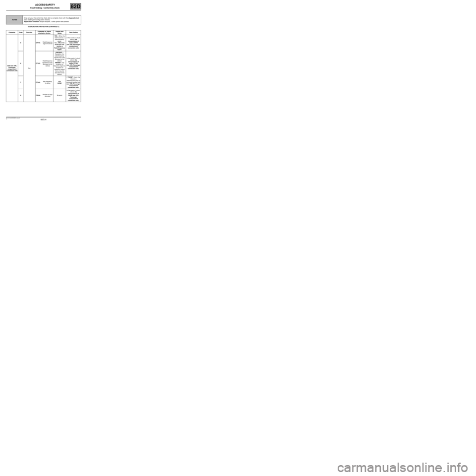
SUB-FUNCTION: PROTECTION (CONTINUED 1)
NOTESOnly carry out this conformity check after a complete check with the diagnostic tool
(fault reading and configuration checks).
Application condition: engine stopped, + after ignition feed present.
Computer Order FunctionParameter or Status
checked or ActionDisplay and
NotesFault finding
UCH (see 87B,
Passenger
compartment
connection unit)5
KeyET045:Radiofrequency
signal receivedYES = When the
UCH receives a
radiofrequency
signal.
NO = When the
UCH does not
receive a
Radiofrequency
signal.In the event of a fault,
refer to the
interpretation of
status ET045
(see 87B, Passenger
compartment
connection unit).
6ET193:Radiofrequency
signal from a key
allocated to the
vehiclePRESENT =
Reception of a
radiofrequency
signal from a key
allocated to the
vehicle.
ABSENT = No
reception of
frequency signal or
reception of
frequency signal
from a key not
allocated to the
vehicle.In the event of a fault,
refer to the
interpretation of
status ET193
(see 87B, Passenger
compartment
connection unit).
7ET240:Key frequency
(in MHz)433
NONEIf "NONE", check that
there is a
radiofrequency key by
trying with another key
(see 87B, Passenger
compartment
connection unit).
8PR056:Number of keys
allocatedX key(s)In the event of a fault,
refer to the
interpretation of
PR056 (see 87B,
Passenger
compartment
connection unit).