RENAULT TWINGO RS 2009 2.G Electrical Equipment Repair Manual
TWINGO RS 2009 2.G
RENAULT
RENAULT
https://www.carmanualsonline.info/img/7/1692/w960_1692-0.png
RENAULT TWINGO RS 2009 2.G Electrical Equipment Repair Manual
Trending: audio, air condition, fuse box location, harnes, roof rack, charging, climate control
Page 51 of 241
83A-2
INSTRUMENT PANEL
Instrument panel: Removal - Refitting
83A
aClip on the instrument panel.
aRefit the instrument panel bolts.
aClip on the instrument panel visor.
II - FINAL OPERATION.
aIf replacing an instrument panel, carry out the neces-
sary operations using the Diagnostic tool (see MR
413 Fault finding, 83A, Instrument panel, Fault
Finding - Replacement of components).
Page 52 of 241
83A-3
INSTRUMENT PANEL
Rev counter: Removal - Refitting
ENGINE REV COUNTER
83A
REMOVAL
OPERATION FOR REMOVAL OF PART
CONCERNED
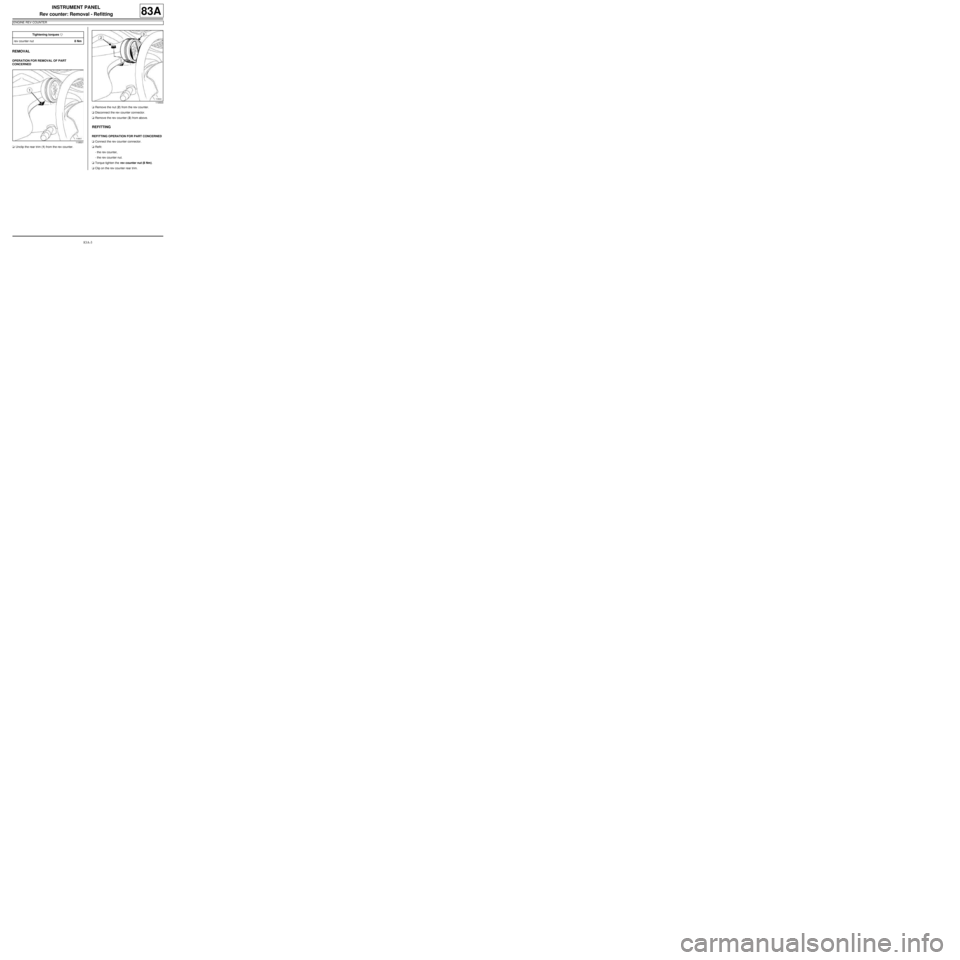
aUnclip the rear trim (1) from the rev counter.aRemove the nut (2) from the rev counter.
aDisconnect the rev counter connector.
aRemove the rev counter (3) from above.
REFITTING
REFITTING OPERATION FOR PART CONCERNED
aConnect the rev counter connector.
aRefit:
-the rev counter,
-the rev counter nut.
aTorque tighten the rev counter nut (8 Nm).
aClip on the rev counter rear trim. Tightening torquesm
rev counter nut8 Nm
119501
119500
Page 53 of 241
83D-1
CRUISE CONTROL
Cruise control - speed limiter: List and location of components
CRUISE CONTROL
83D
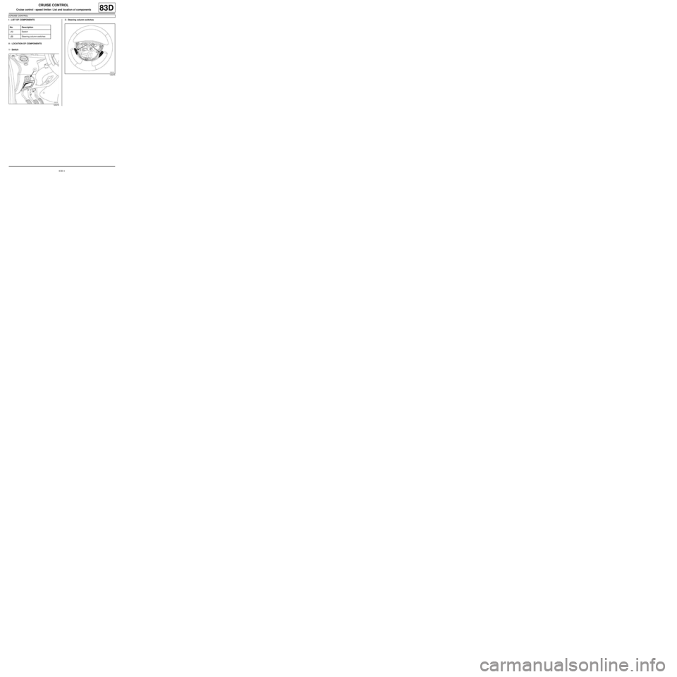
I - LIST OF COMPONENTS
II - LOCATION OF COMPONENTS
1 - Switch2 - Steering column switches
No. Description
(1) Switch
(2) Steering column switches
120278
120275
Page 54 of 241
83D-2
CRUISE CONTROL
Switch: Removal - Refitting
CRUISE CONTROL
83D
REMOVAL
I - REMOVAL PREPARATION OPERATION
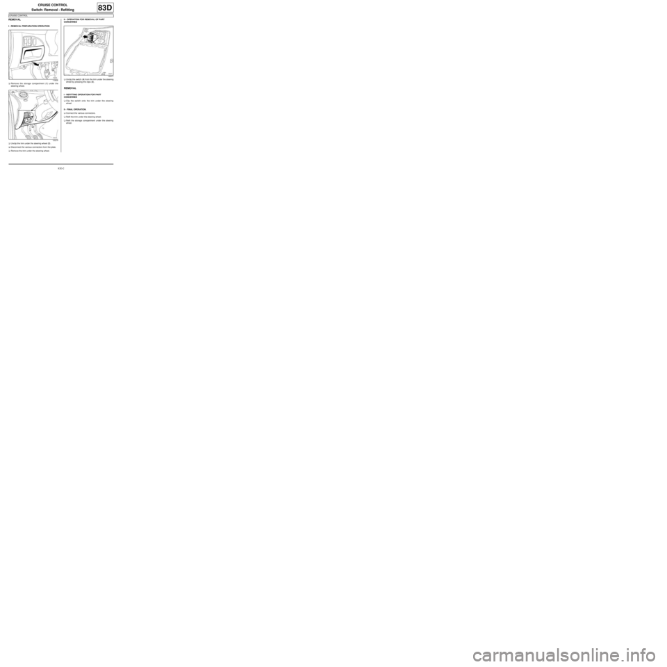
aRemove the storage compartment (1) under the
steering wheel.
aUnclip the trim under the steering wheel (2) .
aDisconnect the various connectors from the plate.
aRemove the trim under the steering wheel.II - OPERATION FOR REMOVAL OF PART
CONCERNED
aUnclip the switch (4) from the trim under the steering
wheel by pressing the clips (3) .
REMOVAL
I - REFITTING OPERATION FOR PART
CONCERNED
aClip the switch onto the trim under the steering
wheel.
II - FINAL OPERATION.
aConnect the various connectors.
aRefit the trim under the steering wheel.
aRefit the storage compartment under the steering
wheel.
119506
120279
120277
Page 55 of 241
83D-3
CRUISE CONTROL
Steering wheel switch: Removal - Refitting
CRUISE CONTROL
83D
The steering column switches cannot be separated
from the steering wheel.
In the event of any faults, replace the steering wheel
(see Steering wheel: Removal - Refitting) (MR 411,
36B, Power-assisted steering).
Page 56 of 241
84A-1
CONTROL - SIGNALS
Steering column switch assembly: List and location of components84A
I - LIST OF COMPONENTS
II - LOCATION OF COMPONENTS
1 - UCH
2 - Steering column switch assembly
(2) : Wiper switch (3) : Indicator light switch
(4) : Telephone/radio control satellite
No. Description
(1) UCH
(2) Windscreen wiper switch
(3) Signalling light switch
(4) Telephone/radio control satellite
119507
119494
Page 57 of 241
84A-2
CONTROL - SIGNALS
Steering column switch assembly: Removal - Refitting84A
REMOVAL
I - REMOVAL PREPARATION OPERATION
a
Set the wheels straight ahead.
aLock the airbag computer using the Diagnostic tool
(see Fault finding - Replacement of components)
(88C, Airbags and pretensioners).
aDisconnect the battery (see 80A, Battery, Battery:
Removal - Refitting, page 80A-2) .
aRemove the rev counter (see 83A, Instrument pa-
nel, Rev counter: Removal - Refitting, page 83A-
3) .aRemove the lower cover bolts (1) .
aUnclip the upper cover at (2) .
aRemove the upper cover (3) . Equipment required
Diagnostic tool
WARNING
To prevent damaging the rotar y switch, do not turn
the mobile section of the rotary switch.
WARNING
Incorrect wheel alignment could ruin the rotary
switch.
ENGINE REV COUNTER
127437
127438
Page 58 of 241
84A-3
CONTROL - SIGNALS
Steering column switch assembly: Removal - Refitting84A
aRemove the lower cover (4) .
aRemove:
-the driver's side front airbag (see 88C, Air bag and
Pretensioners, Driver's frontal airbag: Removal
- Refitting, page 88C-6) ,
-the steering wheel (see Steering wheel: Removal
- Refitting) (36B, Power-assisted steering),II - OPERATION FOR REMOVAL OF PART
CONCERNED
aLock the driver's front airbag (5) connector in the
housing of the radio satellite connector to immobilise
the rotary switch throughout the removal operation.
127439
127766
Page 59 of 241
84A-4
CONTROL - SIGNALS
Steering column switch assembly: Removal - Refitting84A
aDisconnect the steering column switch assembly
connectors.
aRemove the bolt (6) from the steering column switch
assembly.
aUse a flat-blade screwdriver at (7) to release the
steering column switch assembly.
aRemove the steering column switch assembly from
the steering column.
REFITTING
I - REFITTING OPERATION FOR PART
CONCERNED
a
Ensure that the wheels are set straight ahead.a
aRefit the steering column switch assembly to the
steering column.
aConnect the various steering column switch assem-
bly connectors.
127769
WARNING
Incorrect wheel alignment could ruin the rotary
switch.
127767
Note:
Always keep the rotary switch immobilised in (8)
throughout the refitting operation.
Page 60 of 241
84A-5
CONTROL - SIGNALS
Steering column switch assembly: Removal - Refitting84A
aCheck that the rotary switch is positioned correctly:
the outlet for the driver's front airbag (9) wiring
always must be facing upwards.
aAt the last moment, remove the immobilised (10)
connector.
II - FINAL OPERATION.
aRefit:
-the steering wheel (see Steering wheel: Removal
- Refitting) (36B, Power-assisted steering),
-the driver's front airbag (see 88C, Air bag and Pre-
tensioners, Driver's frontal airbag: Removal -
Refitting, page 88C-6) .
-the cowlings under the steering wheel.
aRefit the rev counter (see 83A, Instrument panel,
Rev counter: Removal - Refitting, page 83A-3) .
aConnect the battery (see 80A, Battery, Battery: Re-
moval - Refitting, page 80A-2) .
aUnlock the airbag computer using the Diagnostic
tool (see Fault finding - Replacement of compo-
nents) (88C, Airbags and pretensioners).
aSwitch on the ignition.
aCheck the operation of the rotary switch:
-turn the steering wheel to the left until it stops,-turn the steering wheel to the right until it stops,
-check that there are no faults on the instrument pa-
nel.
127766
ENGINE REV COUNTER
Trending: fuel pump, tow, roof rack, power steering, fuses, service, remove seats
