air filter RENAULT TWINGO RS 2009 2.G Engine And Peripherals Workshop Manual
[x] Cancel search | Manufacturer: RENAULT, Model Year: 2009, Model line: TWINGO RS, Model: RENAULT TWINGO RS 2009 2.GPages: 652
Page 615 of 652

19C-1
TANK
Fuel tank: Draining
K9K
19C
I - DRAINING PREPARATION OPERATION
aDisconnect the battery (see ) (MR 441, 80A, Bat-
tery).
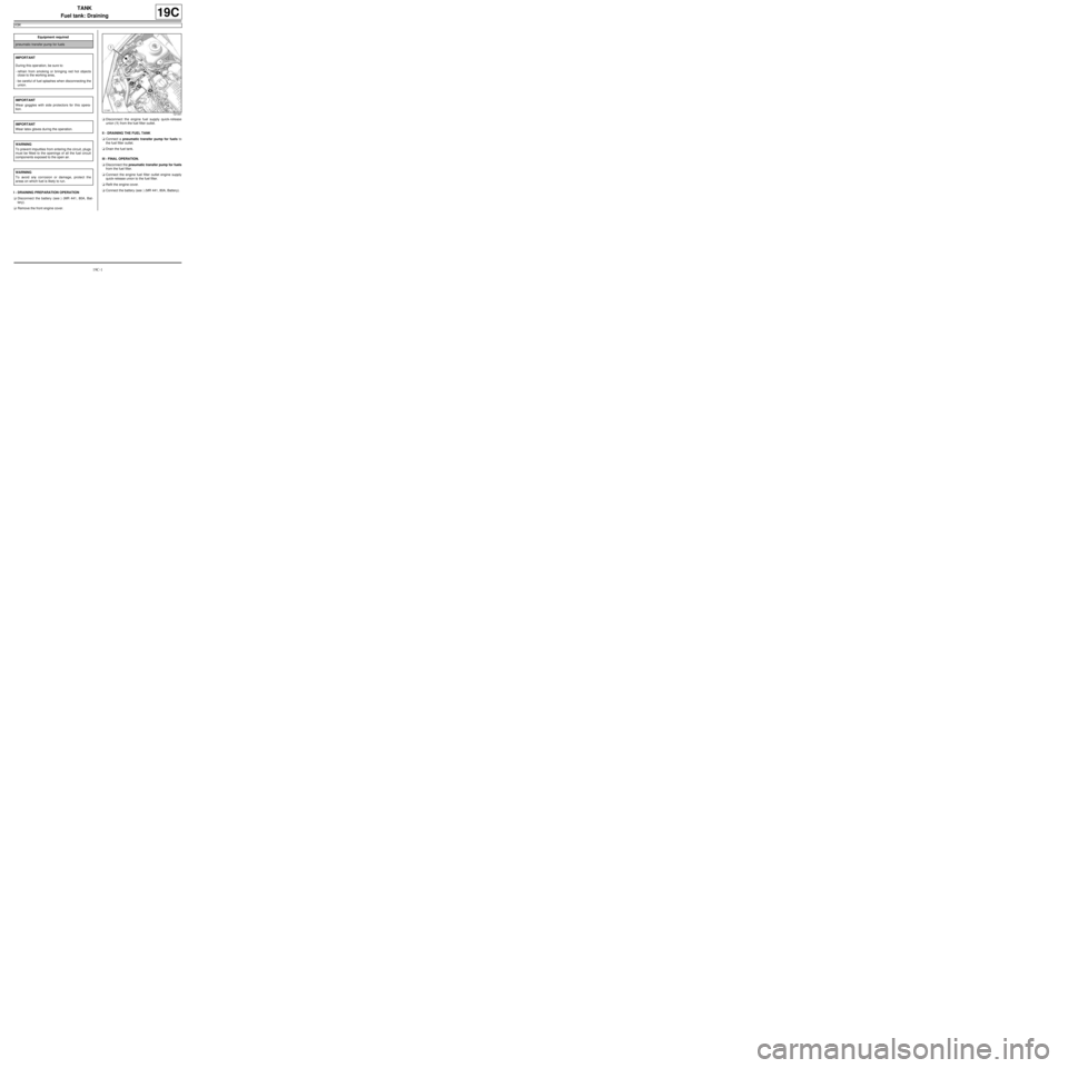
aRemove the front engine cover.aDisconnect the engine fuel supply quick-release
union (1) from the fuel filter outlet.
II - DRAINING THE FUEL TANK
aConnect a pneumatic transfer pump for fuels to
the fuel filter outlet.
aDrain the fuel tank.
III - FINAL OPERATION.
aDisconnect the pneumatic transfer pump for fuels
from the fuel filter.
aConnect the engine fuel filter outlet engine supply
quick-release union to the fuel filter.
aRefit the engine cover.
aConnect the battery (see ) (MR 441, 80A, Battery). Equipment required
pneumatic transfer pump for fuels
IMPORTANT
During this oper ation, be sure to:
-refrain from smoking or bringing red hot objects
close to the working area,
-be careful of fuel splashes when disconnecting the
union.
IMPORTANT
Wear goggles with side protectors for this opera-
tion.
IMPORTANT
Wear latex gloves during the operation.
WARNING
To prevent impurities from entering the circuit, plugs
must be fitted to the openings of all the fuel circuit
components exposed to the open air.
WARNING
To avoid any corrosion or damage, protect the
areas on which fuel is likely to run.
121441
Page 640 of 652

19D-10
ENGINE MOUNTING
Left-hand suspended engine mounting: Removal - Refitting
K4M
19D
REMOVAL
I - REMOVAL PREPARATION OPERATION
aPosition the vehicle on a two-post lift (see Vehicle:
Towing and lifting) (02A, Lifting equipment).
aRemove:
-the battery (see Battery: Removal - Refitting)
(80A, Battery),
-the petrol injection computer (see 17B, Petrol in-
jection, Petrol injection computer: Removal -
Refitting, page 17B-20) ,
-the air filter unit (see 12A, Fuel mixture, Air filter
unit: Removal - Refitting, page 12A-13) ,
-the battery tray (see Battery tray: Removal - Re-
fitting) (80A, Battery),
-the front left-hand wheel (see Wheel: Removal -
Refitting) (35A, Wheels and tyres),
-the front left-hand wheel arch liner (see Front
wheel arch liner: Removal - Refitting) (55A, Ex-
terior protection).
aMark the position of the left-hand suspended engine
mounting.aPut a 20 mm shim between the gearbox and the
sub-frame. Tightening torquesm
bolts of the suspended
engine mounting sup-
por t on the gearbox62 N.m
gearbox suspended
engine mounting rubber
pad shaft105 N.m
bolts of the suspended
engine mounting sup-
por t on the body21 N.m
bolts of the suspended
mounting r ubber pad62 N.m
suspended engine
mounting shaft nut62 N.m
120778
Page 642 of 652

19D-12
ENGINE MOUNTING
Left-hand suspended engine mounting: Removal - Refitting
K4M
19D
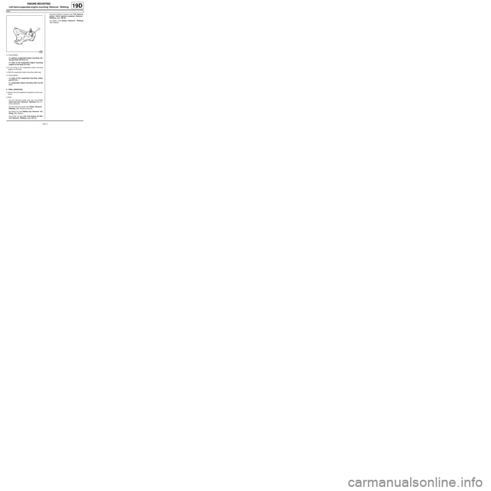
aTorque tighten:
-the gearbox suspended engine mounting rub-
ber pad shaft (105 N.m) (8) ,
-the bolts of the suspended engine mounting
support on the body (21 N.m).
aFit the wiring of the suspended engine mounting
support on the body.
aRefit the suspended engine mounting rubber pad.
aTorque tighten:
-the bolts of the suspended mounting rubber
pad (62 N.m),
-the suspended engine mounting shaft nut (62
N.m).
II - FINAL OPERATION
aRemove the shim between the gearbox and the sub-
frame.
aRefit:
-the front left-hand wheel arch liner (see Front
wheel arch liner: Removal - Refitting) (55A, Ex-
terior protection),
-the front left-hand wheel (see Wheel: Removal -
Refitting) (35A, Wheels and tyres),
-the battery tray (see Battery tray: Removal - Re-
fitting) (80A, Battery),
-the air filter unit (see 12A, Fuel mixture, Air filter
unit: Removal - Refitting, page 12A-13) ,-the petrol injection computer (see 17B, Petrol in-
jection, Petrol injection computer: Removal -
Refitting, page 17B-20) ,
-the battery (see Battery: Removal - Refitting)
(80A, Battery).
130485
Page 643 of 652

19D-13
ENGINE MOUNTING
Right-hand suspended engine mounting: Removal - Refitting
C44, and K9K
19D
PARTS AND CONSUMABLES FOR THE
REPAIR WORK
aParts always to be replaced:
-axle sub-frame bolt.
REMOVAL
I - REMOVAL PREPARATION OPERATION
aPosition the vehicle on a two-post lift ( (see Vehicle:
Towing and lifting) ).
aFit the (1) (Mot. 1672) to the vehicle after removing
the front right-hand bolt on the axle sub-frame and
the rear left-hand bolt on the axle sub-frame.
aSupport the lower engine cover on the (Mot. 1672)
by pressing on the tool support.II - OPERATION FOR REMOVAL OF PART
CONCERNED
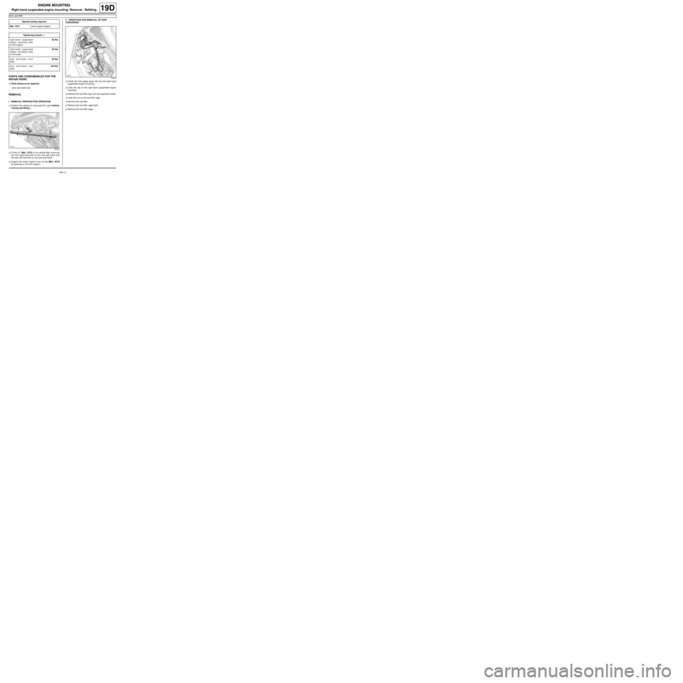
aUnclip the fuel supply pipes (2) from the right-hand
suspended engine mounting.
aUndo the clip on the right-hand suspended engine
mounting.
aRemove the fuel filler cap from the expansion bottle.
aUndo the nut on the fuel filter cage.
aRemove the fuel filter.
aRemove the fuel filter cage bolts.
aRemove the fuel filter cage. Special tooling required
Mot. 1672Low er engine support.
Tightening torquesm
right-hand suspended
engine mounting bolts
on the engine62 Nm
right-hand suspended
engine mounting bolts
on the body62 Nm
axle sub-frame front
bolts62 Nm
axle sub-frame rear
bolts105 Nm
120040
120045