oil temperature RENAULT TWINGO RS 2009 2.G Engine And Peripherals Workshop Manual
[x] Cancel search | Manufacturer: RENAULT, Model Year: 2009, Model line: TWINGO RS, Model: RENAULT TWINGO RS 2009 2.GPages: 652
Page 4 of 652
Contents
Air resonator : Removal -
Refitting 12A-19
Throttle valve: Removal -
Refitting 12A-20
Throttle valve: Cleaning 12A-26
Air flowmeter: Removal -
Refitting 12A-28
Inlet distributor: Removal -
Refitting 12A-29
Injector holder shim:
Removal - Refitting 12A-45
Exhaust manifold: Removal -
Refitting 12A-48
12B TURBOCHARGING
Turbocharging: Precautions
for the repair 12B-1
Turbocharger: Removal -
Refitting 12B-4
Turbocharger oil pipe:
Removal - Refitting 12B-12
Intercooler : Removal -
Refitting 12B-18
13A FUEL SUPPLY
Diesel supply circuit:
Operating diagram 13A-1
Manual pr iming pump:
Removal - Refitting 13A-2
Fuel filter : Removal -
Refitting 13A-4
Electric diesel fuel heater:
Removal - Refitting 13A-7
Fuel circuit: Operating
diagram 13A-8 12A FUEL MIXTUREFuel pressure: Check 13A-9
Fuel flow: Check 13A-14
13B DIESEL INJECTION
Diesel injection: Precautions
for the repair 13B-1
Diesel injection: List and
location of components 13B-8
Diesel injection computer:
Removal - Refitting 13B-13
Camshaft position sensor:
Removal - Refitting 13B-14
Crankshaft position sensor:
Removal - Refitting 13B-15
High pressure pump:
Removal - Refitting 13B-16
Flow actuator: Removal -
Refitting 13B-26
Venturi: Removal - Refitting 13B-31
High pressure pipe: Check 13B-34
High pressure pipe between
pump and rail: Removal -
Refitting 13B-35
High pressure pipe between
rail and injector: Removal -
Refitting 13B-39
Injector rail: Removal -
Refitting 13B-43
Rail pressure sensor:
Removal - Refitting 13B-48
Fuel temperature sensor:
Removal - Refitting 13B-49
Injector leak flow: Check 13B-51
Accelerometer : Removal -
Refitting 13B-53 13A FUEL SUPPLY
Page 65 of 652
10A-59
ENGINE AND CYLINDER BLOCK ASSEMBLY
Oil pressure: Check
D4F or D7F or K9K
10A
I - RECOMMENDATIONS FOR REPAIR
a
II - PARTS AND CONSUMABLES FOR THE REPAIR
WORK
aParts which must be replaced:
-the sump plug sealing washer (in the event of an oil
change),
-oil filter (if removed).
aConsumable:
-Engine oil (see Engine oil: Specifications) (Tech-
nical Note 6013, 04A, Lubricants).
III - CHECK
aRemove the oil pressure sensor (see 10A, Engine
and cylinder block assembly, Oil pressure sen-
sor: Removal - Refitting, page 10A-45) .aCheck the correct operation of the oil pressure sen-
sor valve using the roll pin punch with a diameter of
2 mm and the multimeter. Special tooling required
Mot. 836-05Oil pressure gauge kit.
Mot. 1495-0122 mm socket for removal -
refitting of oxygen sensors.
Equipment required
roll pin punch
multimeter
1/2" long socket (12.7 mm square dr ive)
WARNING
Always check the oil level using the dipstick.
Do not exceed the maximum level on the dipstick
(could destroy the engine).
Correct the engine oil level if necessary before
delivering the vehicle to the customer.
Note:
When topping up the engine oil, always leave at
least 10 minutes before checking the level with a
dipstick.
It is essential to monitor the engine oil pressure
as the engine oil temperature rises (approxi-
mately 80˚C or the first time the engine cool-
ing fan is activated).
Page 66 of 652
10A-60
ENGINE AND CYLINDER BLOCK ASSEMBLY
Oil pressure: Check
D4F or D7F or K9K
10A
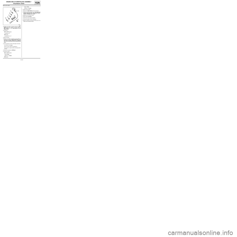
aPosition the engine oil pressure sensor tool (Mot.
836-05) fitted with suitable end pieces using the
(Mot. 1495-01) or a 1/2" long socket (12.7 mm
square drive).
aEnd pieces:
-D4F and D7F engines:
•end piece C + F
-K9K engine:
•end piece E + C + F
aStart the vehicle.
aMonitor the engine oil pressure as the engine oil
temperature increases (approximately 80˚C or the
first time the engine cooling fan is triggered)
which must not be lower than the pressure at idle
speed.
aIf the oil pressure is lower at idle speed, check that:
-the oil filter is not clogged,
-there is no dirt or swarf in the engine oil,
-the oil pump is in good condition and being correct-
ly driven.
aCheck the oil pressure at 3000 rpm.
aCheck the values:
-D4F and D7F engines:
•Idling: 0.8 bar
•3000 rpm: < 3.5 bars
-K9K engine•idling: 1.2 bar
•3000 rpm: < 3.5 bars
aSwitch off the engine.
aRemove the (Mot. 836-05) with the end pieces.
aRefit the oil pressure sensor (see 10A, Engine and
cylinder block assembly, Oil pressure sensor:
Removal - Refitting, page 10A-45) .
aWipe any oil run-off with a cloth.
aWait at least 10 minutes.
aCheck the oil level using the dipstick.
aTop up the engine oil level if necessary.
aStart the vehicle and check that there are no oil
leaks at the oil pressure sensor.
87363
Page 232 of 652
11A-115
TOP AND FRONT OF ENGINE
Cylinder head: Removal - Refitting
K9K
11A
aFit blanking plugs to the fuel pipes and the high pres-
sure pump (see 13B, Diesel injection, Diesel in-
jection: Precautions for the repair, page 13B-1) .
aRemove the air filter unit (see 12A, Fuel mixture,
Air filter unit: Removal - Refitting, page 12A-13) .
aUnclip:
-the breather pipe on the gearbox,
-the wiring on the engine lifting eye on the gearbox
side.
aMove aside the engine wiring.
aDisconnect the brake servo pipe from the vacuum
pump.
aRemove the cooling hose clip from the EGR cooler
using the (Mot. 1202-01) or (Mot. 1202-02) or (Mot.
1448).
aDisconnect the cooling hose from the EGR cooler.
aSeparate the clip on the cooling hose of the coolant
pump inlet pipe using the tool (Mot. 1202-01) or
(Mot. 1202-02) or (Mot. 1448).
aDisconnect the cooling hose from the coolant pump
inlet pipe.
aRemove the heater matrix cooling hose clip from the
water chamber using the (Mot. 1202-01) or (Mot.
1202-02) or (Mot. 1448).
aDisconnect:
-the heater matrix cooling hose from the water
chamber,
-the coolant temperature sensor connector.
aRemove the catalytic converter (see 19B, Exhaust,
Catalytic converter: Removal - Refitting, page
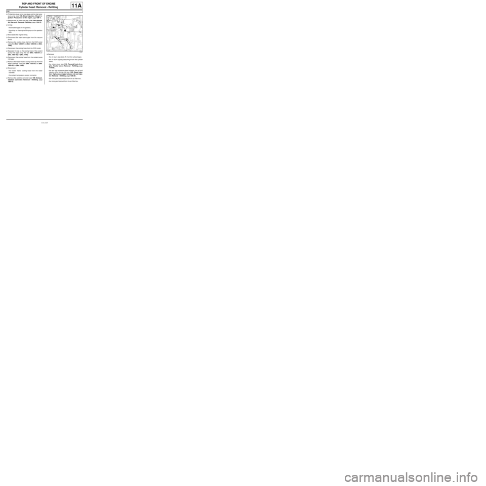
19B-12) .aRemove:
-the oil return pipe bolts (1) from the turbocharger,
-the oil return pipe by detaching it from the cylinder
block,
-the rocker cover (see 11A, Top and front of en-
gine, Rocker cover: Removal - Refitting, page
11A-66) ,
-the two high pressure pipes between the rail and
injector at the timing end (see 13B, Diesel injec-
tion, High pressure pipe between rail and injec-
tor: Removal - Refitting, page 13B-39) ,
-the timing end bracket bolt from the air filter box,
-the timing end bracket from the air filter box.
112327
Page 234 of 652
11A-117
TOP AND FRONT OF ENGINE
Cylinder head: Removal - Refitting
K9K
11A
aIf necessary, carry out a complete check of the cylin-
der head (see Cylinder head: Check) .
II - REFITTING OPERATION FOR PART
CONCERNED
aBring the pistons to mid-stroke position to prevent
them from coming into contact with the valves during
the tightening of the cylinder head.
aRefit:
-a new cylinder head gasket,
-the cylinder head.
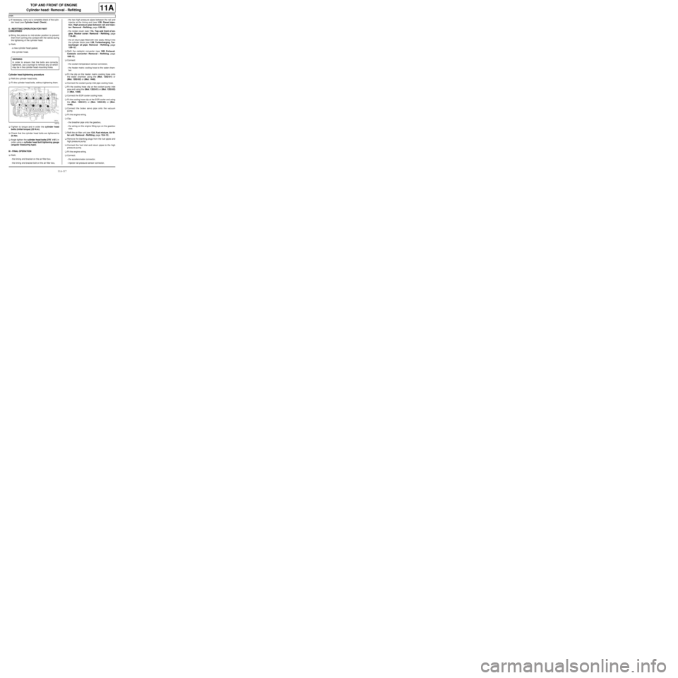
Cylinder head tightening procedure
aRefit the cylinder head bolts.
aFit the cylinder head bolts, without tightening them.
aTighten to torque and in order the cylinder head
bolts (initial torque) (25 N.m).
aCheck that the cylinder head bolts are tightened to
25 Nm.
aAngle tighten the cylinder head bolts (270˚ ±± ± ±
10˚) in
order using a cylinder head bolt tightening gauge
(angular measuring type).
III - FINAL OPERATION
aRefit:
-the timing end bracket on the air filter box.
-the timing end bracket bolt on the air filter box,-the two high pressure pipes between the rail and
injector at the timing end (see 13B, Diesel injec-
tion, High pressure pipe between rail and injec-
tor: Removal - Refitting, page 13B-39) ,
-the rocker cover (see 11A, Top and front of en-
gine, Rocker cover: Removal - Refitting, page
11A-66) ,
-the oil return pipe fitted with new seals, fitting it into
the cylinder block (see 12B, Turbocharging, Tur-
bocharger oil pipe: Removal - Refitting, page
12B-12) .
aRefit the catalytic converter (see 19B, Exhaust,
Catalytic converter: Removal - Refitting, page
19B-12) .
aConnect:
-the coolant temperature sensor connector,
-the heater matrix cooling hose to the water cham-
ber.
aFit the clip on the heater matrix cooling hose onto
the water chamber using the (Mot. 1202-01) or
(Mot. 1202-02) or (Mot. 1448).
aConnect the coolant pump inlet pipe cooling hose.
aFit the cooling hose clip at the coolant pump inlet
pipe end using the (Mot. 1202-01) or (Mot. 1202-02)
or (Mot. 1448).
aConnect the EGR cooler cooling hose.
aFit the cooling hose clip at the EGR cooler end using
the (Mot. 1202-01) or (Mot. 1202-02) or (Mot.
1448).
aConnect the brake servo pipe onto the vacuum
pump.
aFit the engine wiring.
aClip:
-the breather pipe onto the gearbox,
-the wiring on the engine lifting eye on the gearbox
side.
aRefit the air filter unit (see 12A, Fuel mixture, Air fil-
ter unit: Removal - Refitting, page 12A-13) .
aRemove the blanking plugs from the fuel pipes and
high pressure pump.
aConnect the fuel inlet and return pipes to the high
pressure pump.
aFit the engine wiring.
aConnect:
-the accelerometer connector,
-injector rail pressure sensor connector, WARNING
In order to ensure that the bolts are correctly
tightened, use a syringe to remove any oil which
may be in the cylinder head mounting holes.
19712
Page 237 of 652
11A-120
TOP AND FRONT OF ENGINE
Cylinder head: Removal - Refitting
K4M
11A
-the camshafts (see 11A, Top and front of engine,
Camshaft: Removal - Refitting, page 11A-82) .
aDrain the gearbox (see Manual gearbox oils:
Draining - Filling) (21A, Manual gearbox).
aRemove:
-the front right-hand wheel driveshaft (see Front
right-hand driveshaft: Removal - Refitting)
(29A, Driveshafts),
-the exhaust manifold (see 12A, Fuel mixture, Ex-
haust manifold: Removal - Refitting, page 12A-
48) .
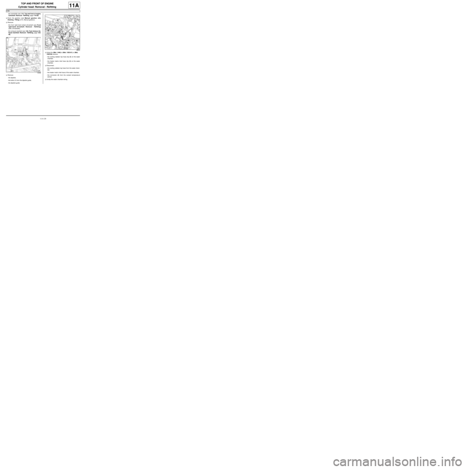
aRemove:
-the dipstick,
-the bolts (1) from the dipstick guide,
-the dipstick guide.aUsing the (Mot. 1448) or (Mot. 1202-01) or (Mot.
1202-02) remove:
-the cooling radiator top hose clip (2) on the water
chamber.
-the heater matrix inlet hose clip (3) on the water
chamber.
aDisconnect:
-the cooling radiator top hose from the water cham-
ber.
-the heater matrix inlet hose of the water chamber,
-the connector (4) from the coolant temperature
sensor.
aUnclip the water chamber wiring.
132368
128616
Page 240 of 652

11A-123
TOP AND FRONT OF ENGINE
Cylinder head: Removal - Refitting
K4M
11A
II - REFITTING OPERATION
aRefit:
-the cylinder head,
-the new cylinder head bolts.
aWithout tightening, fit the cylinder head bolts in or-
der.
aPretighten to torque and in order the cylinder head
bolts (initial torque) (20 N.m).
aCheck that all of the new cylinder head bolts are
tightened to the correct torque (20 N.m).
aAngle tighten in order the cylinder head bolts (240˚
±± ± ±
6˚).III - FINAL OPERATION
aPosition the injector wiring.
aConnect the injector connectors.
aFit the wiring bracket on the water chamber.
aRefit:
-the wiring bracket bolt on the water chamber,
-the bolts of the engine wiring channel.
aClip on the water chamber wiring.
aConnect:
-the coolant temperature sensor connector,
-the heater matrix inlet hose to the water chamber,
-the cooling radiator top hose to the water chamber.
aUsing the (Mot. 1448) or (Mot. 1202-01) or (Mot.
1202-02) fit:
-the cooling radiator top hose clip on the water
chamber,
-the heater matrix inlet hose clip on the water cham-
ber.
aRefit:
-dipstick guide ,
-the dipstick,
-the exhaust manifold (see 12A, Fuel mixture, Ex-
haust manifold: Removal - Refitting, page 12A-
48) .
-the front right-hand wheel driveshaft (see Front
right-hand driveshaft: Removal - Refitting)
(29A, Driveshafts),
-the camshafts (see 11A, Top and front of engine,
Camshaft: Removal - Refitting, page 11A-82) ,
-the rocker cover (see 11A, Top and front of en-
gine, Rocker cover: Removal - Refitting, page
11A-66) ,
-the camshaft seals on the timing end (see 11A,
Top and front of engine, Camshaft seal, timing
end: Removal - Refitting, page 11A-138) ,
-the camshaft dephaser (see 11A, Top and front of
engine, Camshaft dephaser: Removal - Refit-
ting, page 11A-135) ,
-the timing belt (see 11A, Top and front of engine,
Timing belt: Removal - Refitting, page 11A-27) ,
-the crankshaft accessories pulley (see 11A, Top
and front of engine, Crankshaft accessories
pulley: Removal - Refitting, page 11A-20) ,
103259
WARNING
In order to ensure that the bolts are correctly
tightened, use a syringe to remove any oil which
may be in the cylinder head mounting holes.
WARNING
Do not oil the new bolts. Be sure to oil bolts
being reused.
WARNING
Do not retighten the cylinder head bolts after
applying this procedure.
Page 245 of 652
11A-128
TOP AND FRONT OF ENGINE
Cylinder head: Removal - Refitting
D7F – D4F, and 772
11A
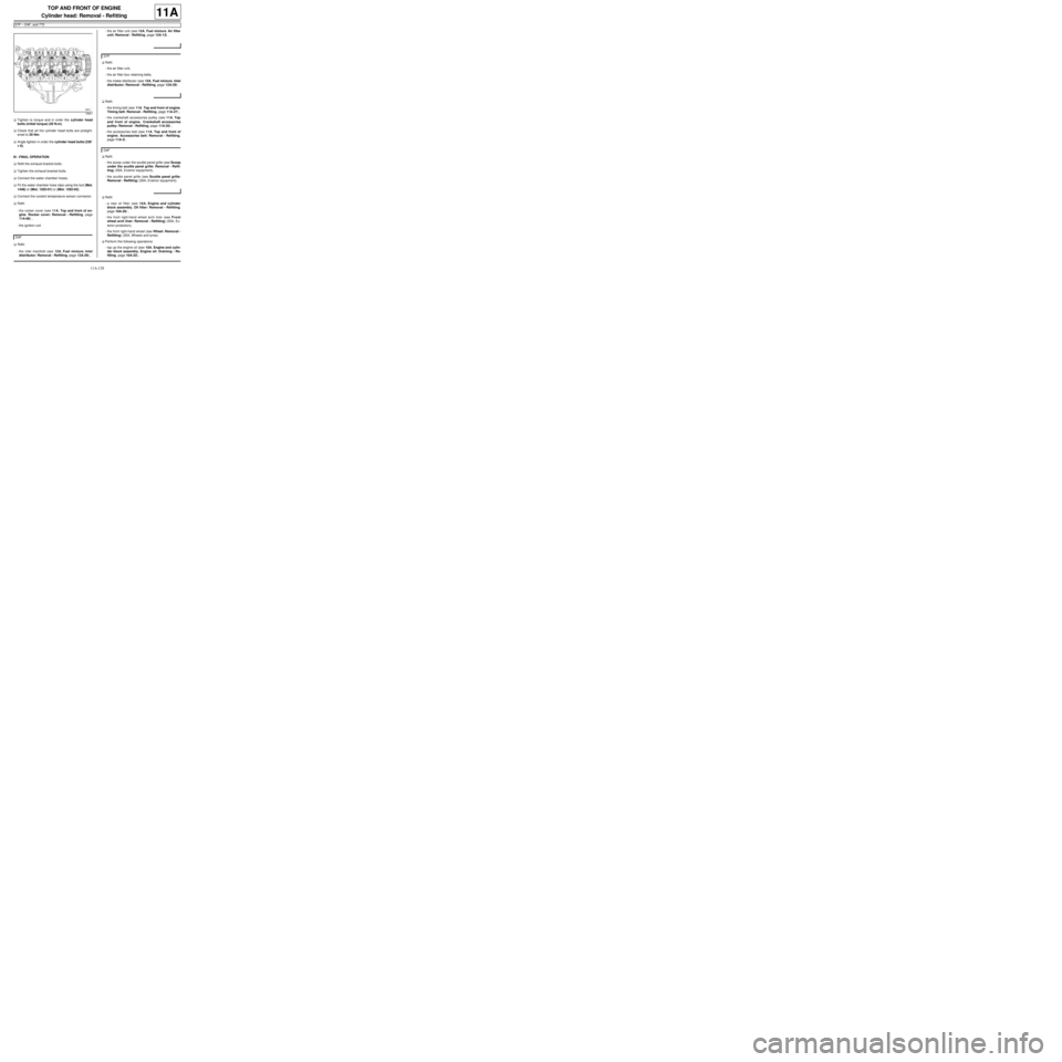
aTighten to torque and in order the cylinder head
bolts (initial torque) (20 N.m).
aCheck that all the cylinder head bolts are pretight-
ened to 20 Nm.
aAngle tighten in order the cylinder head bolts (230˚
±± ± ±
6).
III - FINAL OPERATION
aRefit the exhaust bracket bolts.
aTighten the exhaust bracket bolts.
aConnect the water chamber hoses.
aFit the water chamber hose clips using the tool (Mot.
1448) or (Mot. 1202-01) or (Mot. 1202-02).
aConnect the coolant temperature sensor connector.
aRefit:
-the rocker cover (see 11A, Top and front of en-
gine, Rocker cover: Removal - Refitting, page
11A-66) ,
-the ignition coil.
aRefit:
-the inlet manifold (see 12A, Fuel mixture, Inlet
distributor: Removal - Refitting, page 12A-29) ,-the air filter unit (see 12A, Fuel mixture, Air filter
unit: Removal - Refitting, page 12A-13) .
aRefit:
-the air filter unit,
-the air filter box retaining belts,
-the intake distributor (see 12A, Fuel mixture, Inlet
distributor: Removal - Refitting, page 12A-29) .
aRefit:
-the timing belt (see 11A, Top and front of engine,
Timing belt: Removal - Refitting, page 11A-27) ,
-the crankshaft accessories pulley (see 11A, Top
and front of engine, Crankshaft accessories
pulley: Removal - Refitting, page 11A-20) ,
-the accessories belt (see 11A, Top and front of
engine, Accessories belt: Removal - Refitting,
page 11A-3) .
aRefit:
-the scoop under the scuttle panel grille (see Scoop
under the scuttle panel grille: Removal - Refit-
ting) (56A, Exterior equipment),
-the scuttle panel grille (see Scuttle panel grille:
Removal - Refitting) (56A, Exterior equipment).
aRefit:
-a new oil filter (see 10A, Engine and cylinder
block assembly, Oil filter: Removal - Refitting,
page 10A-29) ,
-the front right-hand wheel arch liner (see Front
wheel arch liner: Removal - Refitting) (55A, Ex-
terior protection),
-the front right-hand wheel (see Wheel: Removal -
Refitting) (35A, Wheels and tyres).
aPerform the following operations:
-top up the engine oil (see 10A, Engine and cylin-
der block assembly, Engine oil: Draining - Re-
filling, page 10A-22) ,
18641
D4F
D7F
D4F
Page 250 of 652
11A-133
TOP AND FRONT OF ENGINE
Cylinder head: Removal - Refitting
D4F, and 780 or 782
11A
2 - Checking the gasket face
aCheck the flatness of the cylinder head gasket face
(see Cylinder head: Check) .
3 - Optional additional operations
aWhen replacing the cylinder head, strip the cylinder
head (see Cylinder head: Stripping - Rebuilding) .
aIf necessary, carry out a complete check of the cylin-
der head (see Cylinder head: Check) .
II - REFITTING OPERATION FOR PART
CONCERNED
aBring the pistons to mid-stroke position to prevent
them from coming into contact with the valves during
the tightening of the cylinder head.
aCheck for the cylinder head centring dowels on the
cylinder block.
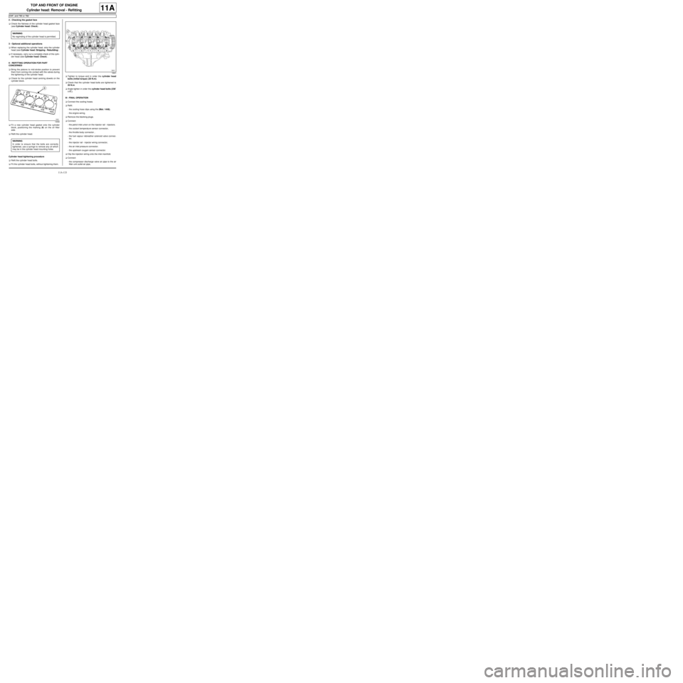
aFit a new cylinder head gasket onto the cylinder
block, positioning the marking (8) on the oil filter
side.
aRefit the cylinder head.
Cylinder head tightening procedure
aRefit the cylinder head bolts.
aFit the cylinder head bolts, without tightening them.aTighten to torque and in order the cylinder head
bolts (initial torque) (20 N.m).
aCheck that the cylinder head bolts are tightened to
20 N.m.
aAngle tighten in order the cylinder head bolts (230˚
±± ± ±
6˚).
III - FINAL OPERATION
aConnect the cooling hoses.
aRefit:
-the cooling hose clips using the (Mot. 1448),
-the engine wiring.
aRemove the blanking plugs.
aConnect:
-the petrol inlet union on the injector rail - injectors.
-the coolant temperature sensor connector,
-the throttle body connector ,
-the fuel vapour rebreather solenoid valve connec-
tor,
-the injector rail - injector wiring connector,
-the air inlet pressure connector.
-the upstream oxygen sensor connector.
aClip the injection wiring onto the inlet manifold.
aConnect:
-the compressor discharge valve air pipe to the air
filter unit outlet air pipe, WARNING
No regrinding of the cylinder head is permitted.
19598
WARNING
In order to ensure that the bolts are correctly
tightened, use a syringe to remove any oil which
may be in the cylinder head mounting holes.
18641
Page 295 of 652
12A-30
FUEL MIXTURE
Inlet distributor: Removal - Refitting
D7F
12A
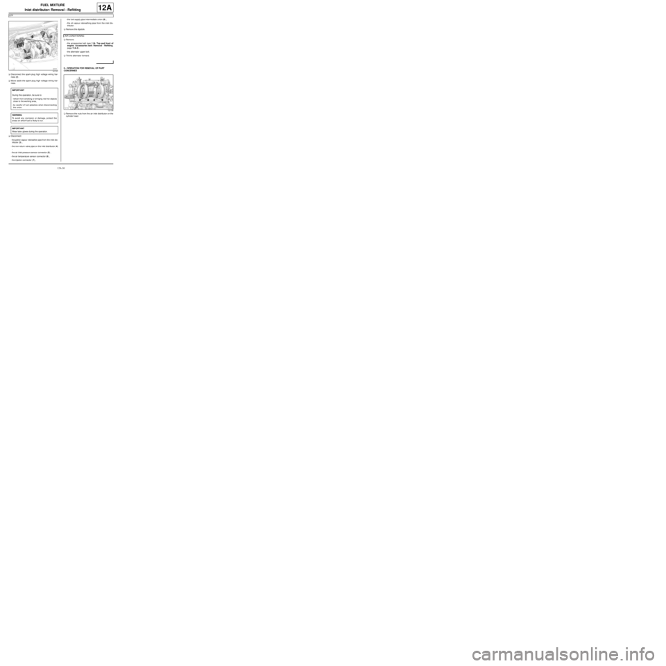
aDisconnect the spark plug high voltage wiring har-
ness (2) .
aMove aside the spark plug high voltage wiring har-
ness.
aDisconnect:
-the petrol vapour rebreather pipe from the inlet dis-
tributor (3) ,
-the non-return valve pipe on the inlet distributor (4)
,
-the air inlet pressure sensor connector (5) ,
-the air temperature sensor connector (6) ,
-the injector connector (7) ,-the fuel supply pipe intermediate union (8) ,
-the oil vapour rebreathing pipe from the inlet dis-
tributor.
aRemove the dipstick.
aRemove:
-the accessories belt (see 11A, Top and front of
engine, Accessories belt: Removal - Refitting,
page 11A-3) ,
-the alternator upper bolt.
aTilt the alternator forward.
II - OPERATION FOR REMOVAL OF PART
CONCERNED
aRemove the nuts from the air inlet distributor on the
cylinder head.
121737
IMPORTANT
During this operation, be sure to:
-refrain from smoking or bringing red hot objects
close to the working area,
-be careful of fuel splashes when disconnecting
the union.
WARNING
To avoid any corrosion or damage, protect the
areas on which fuel is likely to run.
IMPORTANT
Wear latex gloves during the operation.
AIR CONDITIONING
121734