K4M RENAULT TWINGO RS 2009 2.G Engine And Peripherals User Guide
[x] Cancel search | Manufacturer: RENAULT, Model Year: 2009, Model line: TWINGO RS, Model: RENAULT TWINGO RS 2009 2.GPages: 652
Page 32 of 652
10A-26
ENGINE AND CYLINDER BLOCK ASSEMBLY
Engine oil: Draining - Refilling
K4M
10A
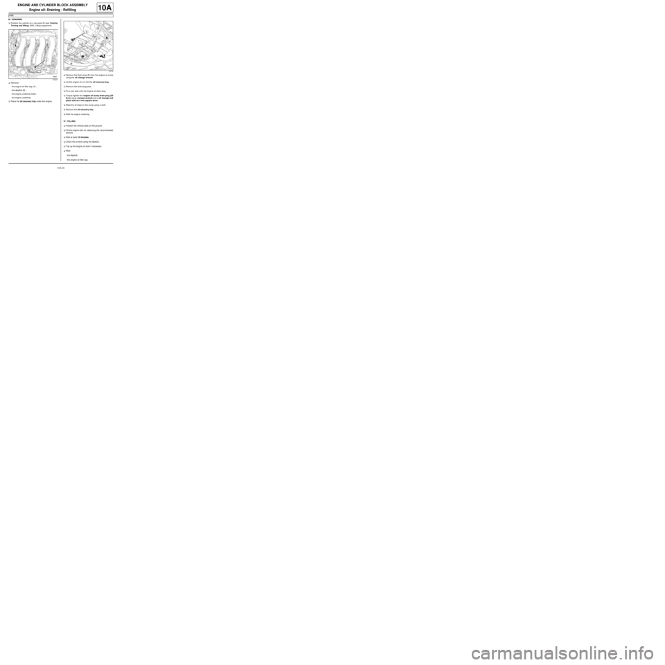
III - DRAINING
aPosition the vehicle on a two-post lift (see Vehicle:
Towing and lifting) (02A, Lifting equipment).
aRemove:
-the engine oil filler cap (1) ,
-the dipstick (2) ,
-the engine undertray bolts,
-the engine undertray.
aPlace the oil recovery tray under the engine.aRemove the drain plug (3) from the engine oil sump
using the oil change wrench.
aLet the engine oil run into the oil recovery tray.
aRemove the drain plug seal.
aFit a new seal onto the engine oil drain plug.
aTorque tighten the engine oil sump drain plug (20
N.m) using a torque wrench and a oil change end
piece with an 8 mm square drive.
aWipe the oil drips on the sump using a cloth.
aRemove the oil recovery tray.
aRefit the engine undertray.
IV - FILLING
aPosition the vehicle back on the ground.
aFill the engine with oil, observing the recommended
amount.
aWait at least 10 minutes.
aCheck the oil level using the dipstick.
aTop up the engine oil level if necessary.
aRefit:
-the dipstick,
-the engine oil filler cap.
132431
18749
Page 37 of 652
10A-31
ENGINE AND CYLINDER BLOCK ASSEMBLY
Oil filter: Removal - Refitting
K4M
10A
REMOVAL
I - REMOVAL PREPARATION OPERATION
aPosition the vehicle on a two-post lift (see Vehicle:
Towing and lifting) (02A, Lifting equipment).
aDisconnect the battery (see Battery: Removal - Re-
fitting) (80A, Battery).
aRemove the engine undertray.
aPosition oil recovery tray under the engine.II - REMOVAL OPERATION
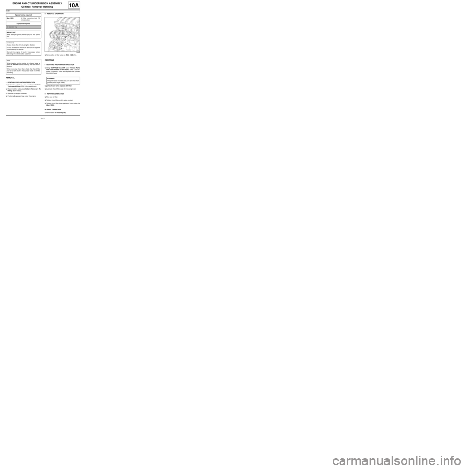
aRemove the oil filter using the (Mot. 1329) (1) .
REFITTING
I - REFITTING PREPARATION OPERATION
aUsing SURFACE CLEANER (see Vehicle: Parts
and consumables for the repair) (04B, Consum-
ables - Products), clean and degrease the cylinder
block joint faces.
aparts always to be replaced: Oil filter.
aLubricate the oil filter seal with new engine oil.
II - REFITTING OPERATION
aFit a new oil filter.
aTighten the oil filter until it makes contact.
aTighten the oil filter three-quarters of a turn using the
(Mot. 1329).
III - FINAL OPERATION
aRemove the oil recovery tray. Special tooling required
Mot. 1329Oil filter removing tool (76
mm diameter)
Equipment required
oil recovery tray
IMPORTANT
Wear leaktight gloves (Nitrile type) for this opera-
tion.
WARNING
Always check the oil level using the dipstick.
Do not exceed the maximum level on the dipstick
(could destroy the engine).
Correct the engine oil level if necessary before
deliver ing the vehicle to the customer.
Note:
When topping up the engine oil, always leave at
least 10 minutes before checking the level with a
dipstick.
When removing the oil filter, check that the oil filter
seal is not still stuck to the cylinder block or oil filter
mounting.
132364
WARNING
The joint faces must be clean, dr y and free from
grease (avoid finger marks).
Page 38 of 652
10A-32
ENGINE AND CYLINDER BLOCK ASSEMBLY
Oil filter: Removal - Refitting
K4M
10A
aWipe any oil run-off with a cloth.
aTop up the engine oil with oil recommended by the
manufacturer (see Engine oil: Specifications)
(Technical Note 6013A, 04A, Lubricants).
aConnect the battery (see Battery: Removal - Refit-
ting) (80A, Battery).
aStart the engine and wait until the oil pressure warn-
ing light goes out on the instrument panel.
aCheck for leaks from the oil filter.
aRefit the engine undertray.
aWait at least 10 minutes.
aCheck the oil level using the dipstick.
aAdjust the engine oil level if necessary.WARNING
Always check the oil level using the dipstick.
Do not exceed the maximum level on the dipstick
(could destroy the engine).
Correct the engine oil level if necessary before
delivering the vehicle to the customer.
Page 54 of 652
10A-48
ENGINE AND CYLINDER BLOCK ASSEMBLY
Oil pressure sensor: Removal - Refitting
K4M
10A
REMOVAL
I - REMOVAL PREPARATION OPERATION
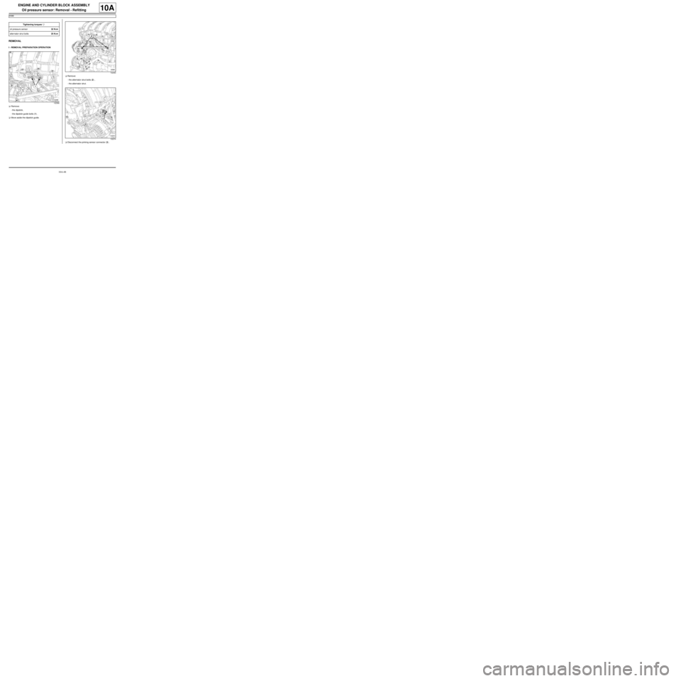
aRemove:
-the dipstick,
-the dipstick guide bolts (1) .
aMove aside the dipstick guide.aRemove:
-the alternator strut bolts (2) ,
-the alternator strut.
aDisconnect the pinking sensor connector (3) . Tightening torquesm
oil pressure sensor32 N.m
alter nator strut bolts25 N.m
132368
132363
132374
Page 55 of 652
10A-49
ENGINE AND CYLINDER BLOCK ASSEMBLY
Oil pressure sensor: Removal - Refitting
K4M
10A
II - REMOVAL OPERATION
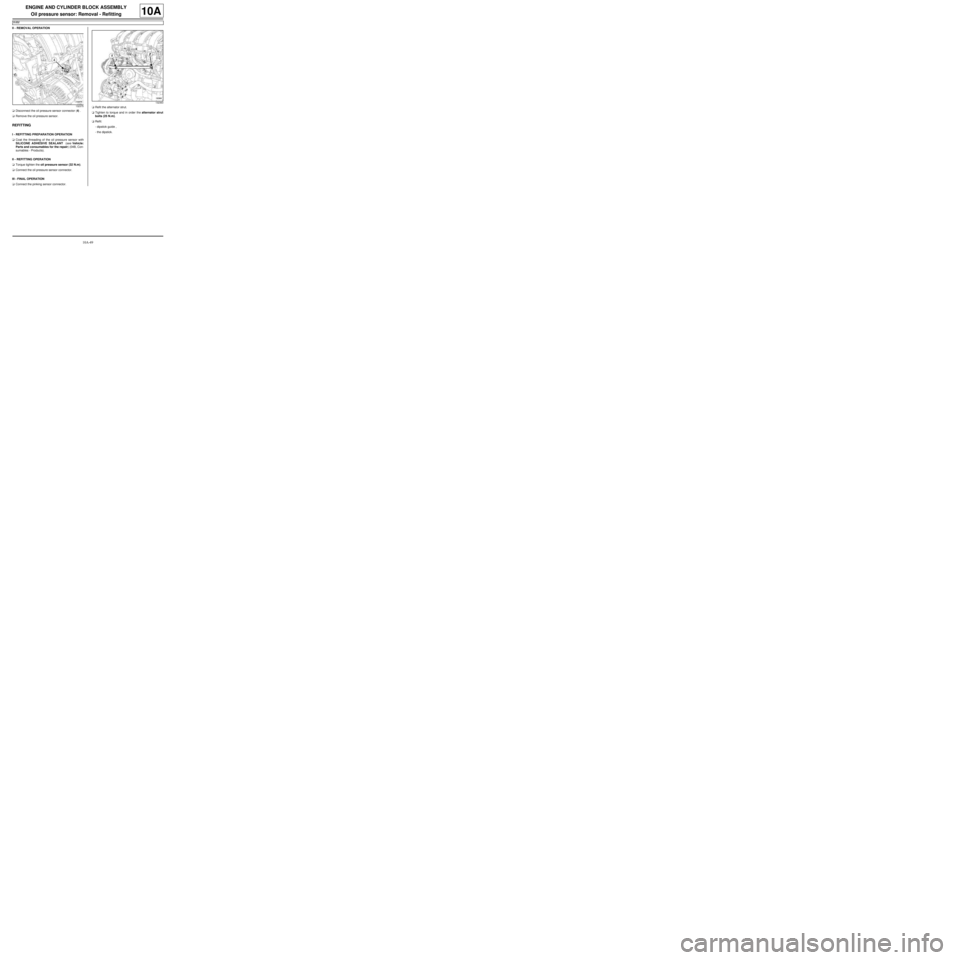
aDisconnect the oil pressure sensor connector (4) .
aRemove the oil pressure sensor.
REFITTING
I - REFITTING PREPARATION OPERATION
aCoat the threading of the oil pressure sensor with
SILICONE ADHESIVE SEALANT (see Vehicle:
Parts and consumables for the repair) (04B, Con-
sumables - Products).
II - REFITTING OPERATION
aTorque tighten the oil pressure sensor (32 N.m).
aConnect the oil pressure sensor connector.
III - FINAL OPERATION
aConnect the pinking sensor connector.aRefit the alternator strut.
aTighten to torque and in order the alternator strut
bolts (25 N.m).
aRefit:
-dipstick guide ,
-the dipstick.
132375
132363
Page 63 of 652
10A-57
ENGINE AND CYLINDER BLOCK ASSEMBLY
Oil pump: Removal - Refitting
K4M
10A
REMOVAL
I - REMOVAL PREPARATION OPERATION
aPosition the vehicle on a two-post lift (see Vehicle:
Towing and lifting) (02A, Lifting equipment).
aRemove:
-the front wheels (see Wheel: Removal - Refitting)
(35A, Wheels and tyres),
-the engine undertray.
aDrain the engine oil (see 10A, Engine and cylinder
block assembly, Engine oil: Draining - Refilling,
page 10A-22) .
aRemove:
-the front wheel arch liners (see Front wheel arch
liner: Removal - Refitting) (55A, Exterior protec-
tion),
-the front bumper (see Front bumper: Removal -
Refitting) (55A, Exterior protection),
-the rear engine tie-bar (see 19D, Engine mount-
ing, Lower engine tie-bar: Removal - Refitting,
page 19D-18) ,
-the front axle subframe (see Front axle subframe:
Removal - Refitting) (31A, Front axle compo-
nents).
aRemove the sump (see 10A, Engine and cylinder
block assembly, Lower cover: Removal - Refit-
ting, page 10A-6) .II - REMOVAL OPERATION
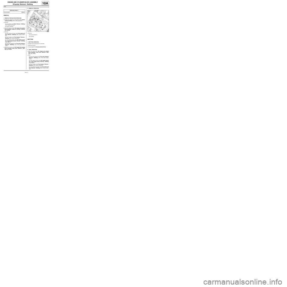
aRemove:
-the oil pump bolts (1) ,
-the oil pump.
REFITTING
I - REFITTING OPERATION
aPosition the oil pump pinion on the chain.
aRefit the oil pump.
aTorque tighten the oil pump bolts (25 N.m).
II - FINAL OPERATION
aRefit the sump (see 10A, Engine and cylinder
block assembly, Lower cover: Removal - Refit-
ting, page 10A-6) .
aRefit:
-the front axle subframe (see Front axle subframe:
Removal - Refitting) (31A, Front axle compo-
nents),
-the rear engine tie-bar (see 19D, Engine mount-
ing, Lower engine tie-bar: Removal - Refitting,
page 19D-18) ,
-the front bumper (see Front bumper: Removal -
Refitting) (55A, Exterior protection),
-the front wheel arch liners (see Front wheel arch
liner: Removal - Refitting) (55A, Exterior protec-
tion), Tightening torquesm
oil pump bolts25 N.m
128799
Page 64 of 652
10A-58
ENGINE AND CYLINDER BLOCK ASSEMBLY
Oil pump: Removal - Refitting
K4M
10A
-the front wheels (see Wheel: Removal - Refitting)
(35A, Wheels and tyres).
aTop up the engine oil (see 10A, Engine and cylin-
der block assembly, Engine oil: Draining - Refill-
ing, page 10A-22) .
aRefit the engine undertray.
Page 67 of 652
10A-61
ENGINE AND CYLINDER BLOCK ASSEMBLY
Oil pressure: Check
K4M
10A
Oil pressure tables:
End pieces to be used:
I - REMOVAL PREPARATION OPERATION
a
II - CHECK
aRemove the oil pressure sensor (see 10A, Engine
and cylinder block assembly, Oil pressure sen-
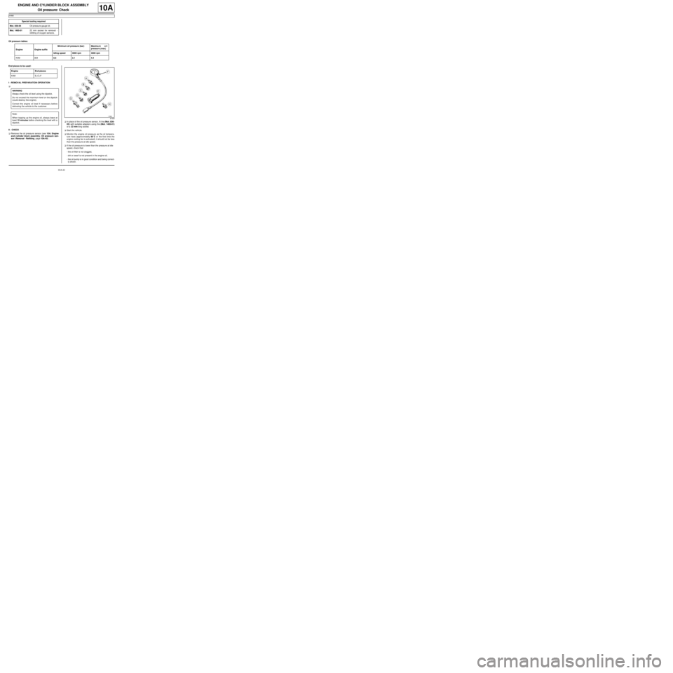
sor: Removal - Refitting, page 10A-45) .aIn place of the oil pressure sensor, fit the (Mot. 836-
05) with suitable adapters using the (Mot. 1495-01)
or a 22 mm long socket.
aStart the vehicle.
aMonitor the engine oil pressure as the oil tempera-
ture rises (approximately 80˚C or the first time the
engine cooling fan is activated); it should not be less
than the pressure at idle speed.
aIf the oil pressure is lower than the pressure at idle
speed, check that:
-the oil filter is not clogged,
-dirt or swarf is not present in the engine oil,
-the oil pump is in good condition and being correct-
ly driven. Special tooling required
Mot. 836-05Oil pressure gauge kit.
Mot. 1495-0122 mm socket for removal -
refitting of oxygen sensors.
Engine Engine suffixMinimum oil pressure (bar) Maximu m o i l
pressure (max)
Idling speed 4000 rpm 4000 rpm
K4M 8540.5 3.1 4.4
Engine End pieces
K4M E+C+F
WARNING
Always check the oil level using the dipstick.
Do not exceed the maximum level on the dipstick
(could destroy the engine).
Correct the engine oil level if necessary before
delivering the vehicle to the customer.
Note:
When topping up the engine oil, always leave at
least 10 minutes before checking the level with a
dipstick.
87363
Page 68 of 652
10A-62
ENGINE AND CYLINDER BLOCK ASSEMBLY
Oil pressure: Check
K4M
10A
aCheck the oil pressure in comparison with the values
given in the table above.
aSwitch off the engine.
aRemove the (Mot. 836-05) with the end pieces.
aRefit the oil pressure sensor (see 10A, Engine and
cylinder block assembly, Oil pressure sensor:
Removal - Refitting, page 10A-45) .
aWipe any oil run-off with a cloth.
aWait at least 10 minutes.
aCheck the oil level using the dipstick.
aTop up the oil level if necessary (see Engine oil:
Specifications) (Technical Note 6013A, 04A, Lubri-
cants).
aStart the vehicle and check that there are no oil
leaks at the oil pressure sensor.
Page 77 of 652
10A-71
ENGINE AND CYLINDER BLOCK ASSEMBLY
Multifunction support: Removal - Refitting
K4M
10A
REMOVAL
I - REMOVAL PREPARATION OPERATION
aPosition the vehicle on a two-post lift (see Vehicle:
Towing and lifting) (02A, Lifting equipment).
aDisconnect the battery (see Battery: Removal - Re-
fitting) (80A, Battery).
aRemove the engine undertray.
aDrain the refrigerant circuit using a refrigerant
charging station (see Refrigerant circuit: Drain-
ing - Filling) (62A, Air conditioning).
aRemove:
-the front right-hand wheel (see Wheel: Removal -
Refitting) (35A, Wheels and tyres),
-the front right-hand wheel arch liner (see Front
wheel arch liner: Removal - Refitting) (55A, Ex-
terior protection),
-the front bumper (see Front bumper: Removal -
Refitting) (55A, Exterior protection),
-the headlights (see Halogen headlight: Removal
- Refitting) (80B, Headlights),
-the bonnet catch (see Bonnet lock: Removal -
Refitting) (52A, Non-side opening element mecha-
nisms),-the front upper cross member (see Front upper
cross member: Removal - Refitting) (42A, Upper
front structure),
-the accessories belt (see 11A, Top and front of
engine, Accessories belt: Removal - Refitting,
page 11A-3) ,
-the alternator (see 16A, Starting - Charging, Al-
ternator: Removal - Refitting, page 16A-1) ,
-the air conditioning compressor (see Compressor:
Removal - Refitting) (62A, Air conditioning). Equipment required
refrigerant charging station
Tightening torquesm
multifunction support
bolts 1 and 2 (initial
torque)5 N.m
multifunction support
bolt 7 on the cylinder
block (initial torque)5 N.m
multifunction support
bolts 6, 5, 4 and 35 N.m
multifunction support
bolts44 N.m
multifunction support
bolt on the cylinder
block25 N.m