K4M RENAULT TWINGO RS 2009 2.G Engine And Peripherals Workshop Manual
[x] Cancel search | Manufacturer: RENAULT, Model Year: 2009, Model line: TWINGO RS, Model: RENAULT TWINGO RS 2009 2.GPages: 652
Page 7 of 652
10A-1
ENGINE AND CYLINDER BLOCK ASSEMBLY
Crankshaft seal on timing end: Removal - Refitting
K4M
10A
REMOVAL
I - REMOVAL PREPARATION OPERATION
aPosition the vehicle on a two-post lift (see Vehicle:
Towing and lifting) (02A, Lifting equipment).
aDisconnect the battery (see Battery: Removal - Re-
fitting) (80A, Battery).
aRemove:
-the engine undertray,
-the front right-hand wheel (see Wheel: Removal -
Refitting) (35A, Wheels and tyres),
-the front right-hand wheel arch liner (see Front
wheel arch liner: Removal - Refitting) (55A, Ex-
terior protection),
-the front bumper (see Front bumper: Removal -
Refitting) (55A, Exterior protection),
-the headlights (see Halogen headlight: Removal
- Refitting) (80B, Headlights),
-the bonnet catch (see Bonnet lock: Removal -
Refitting) (52A, Non-side opening element mecha-
nisms),
-the front upper cross member (see Front upper
cross member: Removal - Refitting) (42A, Upper
front structure),
-the accessories belt (see 11A, Top and front of
engine, Accessories belt: Removal - Refitting,
page 11A-3) ,
-the air filter unit (see 12A, Fuel mixture, Air filter
unit: Removal - Refitting, page 12A-13) ,
-the throttle valve (see 12A, Fuel mixture, Throttle
valve: Removal - Refitting, page 12A-20) ,
-the windscreen wiper arms (see Windscreen wip-
er arm: Removal - Refitting) (85A, Wiping -
Washing),
-the scuttle panel grille (see Scuttle panel grille:
Removal - Refitting) (56A, Exterior equipment),
-the scoop under the scuttle panel grille (see Scoop
under the scuttle panel grille: Removal - Refit-
ting) (56A, Exterior equipment),-the right-hand suspended engine mounting (see
19D, Engine mounting, Right-hand suspended
engine mounting: Removal - Refitting, page
19D-13) ,
-the crankshaft accessories pulley (see 11A, Top
and front of engine, Crankshaft accessories
pulley: Removal - Refitting, page 11A-20) ,
-the timing belt (see 11A, Top and front of engine,
Timing belt: Removal - Refitting, page 11A-27) ,
-the camshaft dephaser (see 11A, Top and front of
engine, Camshaft dephaser: Removal - Refit-
ting, page 11A-135) .
II - REMOVAL OPERATION
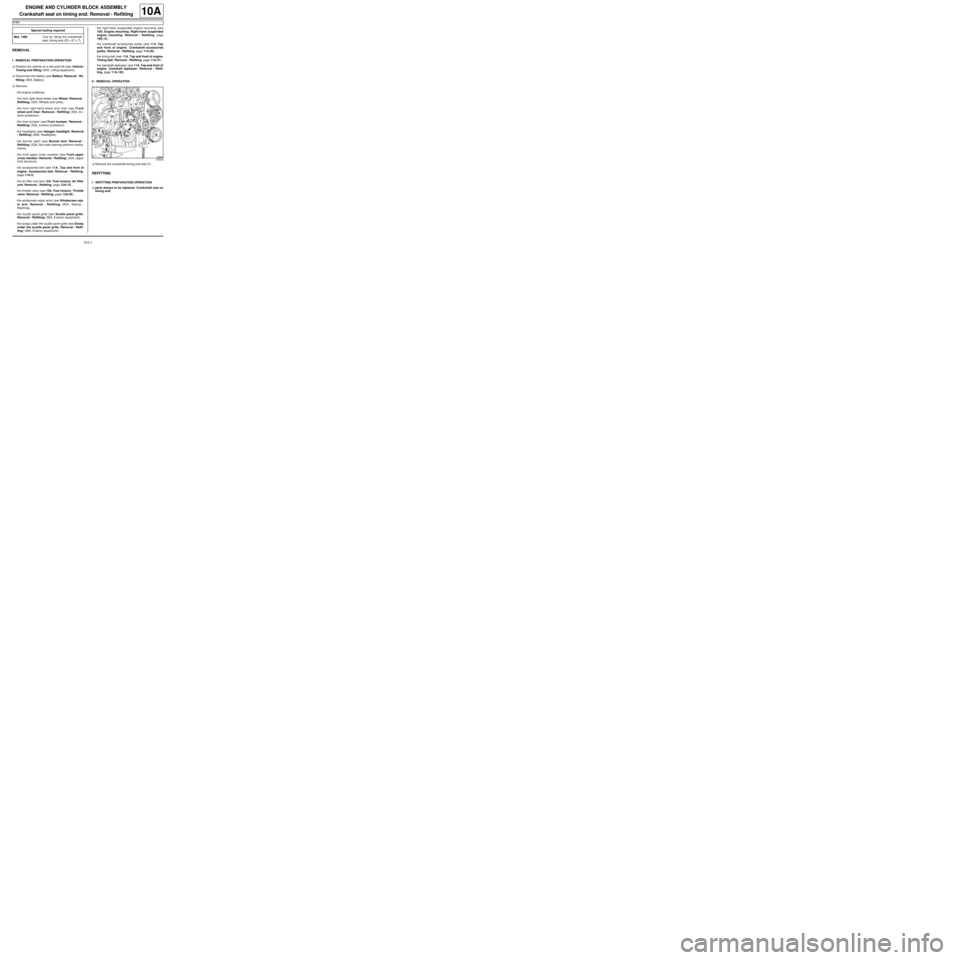
aRemove the crankshaft timing end seal (1) .
REFITTING
I - REFITTING PREPARATION OPERATION
aparts always to be replaced: Crankshaft seal on
timing end. Special tooling required
Mot. 1385Tool for fitting the crankshaft
seal, timing end (35 x 47 x 7).
130542
Page 8 of 652
10A-2
ENGINE AND CYLINDER BLOCK ASSEMBLY
Crankshaft seal on timing end: Removal - Refitting
K4M
10A
aUse SURFACE CLEANER (see Vehicle: Parts
and consumables for the repair) (04B, Consuma-
bles - Products) to clean and degrease:
-the mating face of the crankshaft seal at the timing
end,
-the crankshaft seal housing at the timing end of the
cylinder block.
II - REFITTING OPERATION
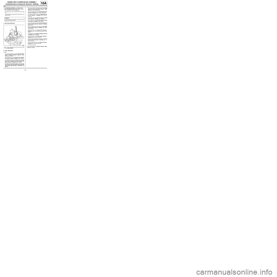
aRefit a new crankshaft seal at the timing end, using
the tool (Mot. 1385) (2) .
III - FINAL OPERATION
aRefit:
-the camshaft dephaser (see 11A, Top and front of
engine, Camshaft dephaser: Removal - Refit-
ting, page 11A-135) ,
-the timing belt (see 11A, Top and front of engine,
Timing belt: Removal - Refitting, page 11A-27) ,
-the crankshaft accessories pulley (see 11A, Top
and front of engine, Crankshaft accessories
pulley: Removal - Refitting, page 11A-20) ,
-the right-hand suspended engine mounting (see
19D, Engine mounting, Right-hand suspended
engine mounting: Removal - Refitting, page
19D-13) ,-the scoop under the scuttle panel grille (see Scoop
under the scuttle panel grille: Removal - Refit-
ting) (56A, Exterior equipment),
-the scuttle panel grille (see Scuttle panel grille:
Removal - Refitting) (56A, Exterior equipment),
-the windscreen wiper arms (see Windscreen wip-
er arm: Removal - Refitting) (85A, Wiping -
Washing),
-the throttle valve (see 12A, Fuel mixture, Throttle
valve: Removal - Refitting, page 12A-20) ,
-the air filter unit (see 12A, Fuel mixture, Air filter
unit: Removal - Refitting, page 12A-13) ,
-the accessories belt (see 11A, Top and front of
engine, Accessories belt: Removal - Refitting,
page 11A-3) ,
-the front upper cross member (see Front upper
cross member: Removal - Refitting) (42A, Upper
front structure),
-the bonnet catch (see Bonnet lock: Removal -
Refitting) (52A, Non-side opening element mecha-
nisms),
-the headlights (see Halogen headlight: Removal
- Refitting) (80B, Headlights),
-the front bumper (see Front bumper: Removal -
Refitting) (55A, Exterior protection),
-the front right-hand wheel arch liner (see Front
wheel arch liner: Removal - Refitting) (55A, Ex-
terior protection),
-the front right-hand wheel (see Wheel: Removal -
Refitting) (35A, Wheels and tyres),
-the engine undertray.
aConnect the battery (see Battery: Removal - Refit-
ting) (80A, Battery). WARNING
The joint faces must be clean, dr y and free from
grease (avoid finger marks).
14523
Page 9 of 652
10A-3
ENGINE AND CYLINDER BLOCK ASSEMBLY
Crankshaft seal, gearbox end: Removal - Refitting
K4M
10A
REMOVAL
I - REMOVAL PREPARATION OPERATION
aPosition the vehicle on a two-post lift (see Vehicle:
Towing and lifting) (02A, Lifting equipment).
aRemove:
-the engine undertray,
-the battery (see Battery: Removal - Refitting)
(80A, Battery),
-the air filter unit (see 12A, Fuel mixture, Air filter
unit: Removal - Refitting, page 12A-13) ,
-the petrol injection computer (see 17B, Petrol in-
jection, Petrol injection computer: Removal -
Refitting, page 17B-20) ,
-the battery tray (see Battery tray: Removal - Re-
fitting) (80A, Battery),
-the front wheels (see Wheel: Removal - Refitting)
(35A, Wheels and tyres),
-the front wheel arch liners (see Front wheel arch
liner: Removal - Refitting) (55A, Exterior protec-
tion),
-the front bumper (see Front bumper: Removal -
Refitting) (55A, Exterior protection).
aDrain:
-the gearbox (see Manual gearbox oils: Draining -
Filling) (21A, Manual gearbox),
-the engine cooling system (see 19A, Cooling,
Cooling system: Draining - Refilling, page 19A-
9) ,
-the refrigerant circuit using a refrigerant charging
station (see Refrigerant circuit: Draining - Fill-
ing) (62A, Air conditioning).
aRemove:
-the lower engine tie-bar (see 19D, Engine mount-
ing, Lower engine tie-bar: Removal - Refitting,
page 19D-18) ,-the front axle subframe (see Front axle subframe:
Removal - Refitting) (31A, Front axle compo-
nents),
-the front left-hand wheel driveshaft (see Front left-
hand driveshaft: Removal - Refitting) (29A,
Driveshafts),
-the front right-hand wheel driveshaft (see Front
right-hand driveshaft: Removal - Refitting)
(29A, Driveshafts),
-the differential output seals (see Differential out-
put seal: Removal - Refitting) (21A, Manual gear-
box),
-the « engine and gearbox » assembly (see 10A,
Engine and cylinder block assembly, Engine -
gearbox assembly: Removal - Refitting, page
10A-74) ,
-the manual gearbox (see Manual gearbox: Re-
moval - Refitting) (21A, Manual gearbox).
-the « pressure plate - disc » assembly (see Pres-
sure plate - Disc: Removal - Refitting) (20A,
Clutch),
-the flywheel (see 10A, Engine and cylinder block
assembly, Flywheel: Removal - Refitting, page
10A-107) . Special tooling required
Mot. 1129-01Tool for fitting the crankshaft
seal, flywheel end (80 x 100 x
8 seal).
Equipment required
refrigerant charging station
Page 10 of 652
10A-4
ENGINE AND CYLINDER BLOCK ASSEMBLY
Crankshaft seal, gearbox end: Removal - Refitting
K4M
10A
II - REMOVAL OPERATION
aRemove the crankshaft seal (1) at the gearbox end
using a screwdriver.
REFITTING
I - REFITTING PREPARATION OPERATION
aparts always to be replaced: Crankshaft seal on
gearbox end.
aUse SURFACE CLEANER (see Vehicle: Parts
and consumables for the repair) (04B, Consuma-
bles - Products) to clean and degrease:
-the mating face of the crankshaft seal at the gear-
box end,
-the crankshaft seal housing at the gearbox end of
the cylinder block.II - REFITTING OPERATION
aRefit a new crankshaft seal at the gearbox end, us-
ing the tool (Mot. 1129-01) (2) .
III - FINAL OPERATION
aRefit:
-the flywheel (see 10A, Engine and cylinder block
assembly, Flywheel: Removal - Refitting, page
10A-107) ,
-the « pressure plate - disc » assembly (see Pres-
sure plate - Disc: Removal - Refitting) (20A,
Clutch),
-the manual gearbox (see Manual gearbox: Re-
moval - Refitting) (21A, Manual gearbox).
-the « engine and gearbox » assembly (see 10A,
Engine and cylinder block assembly, Engine -
gearbox assembly: Removal - Refitting, page
10A-74) ,
-the differential output seals (see Differential out-
put seal: Removal - Refitting) (21A, Manual gear-
box),
-the front right-hand wheel driveshaft (see Front
right-hand driveshaft: Removal - Refitting)
(29A, Driveshafts),
-the front left-hand wheel driveshaft (see Front left-
hand driveshaft: Removal - Refitting) (29A,
Driveshafts),
-the front axle subframe (see Front axle subframe:
Removal - Refitting) (31A, Front axle compo-
nents),
118581
Note:
Take care not to damage the crankshaft mating
face.
WARNING
The joint faces must be clean, dr y and free from
grease (avoid finger marks).
132380
Page 11 of 652
10A-5
ENGINE AND CYLINDER BLOCK ASSEMBLY
Crankshaft seal, gearbox end: Removal - Refitting
K4M
10A
-the lower engine tie-bar (see 19D, Engine mount-
ing, Lower engine tie-bar: Removal - Refitting,
page 19D-18) ,
-the front bumper (see Front bumper: Removal -
Refitting) (55A, Exterior protection),
-the front wheel arch liners (see Front wheel arch
liner: Removal - Refitting) (55A, Exterior protec-
tion),
-the front wheels (see Wheel: Removal - Refitting)
(35A, Wheels and tyres),
-the battery tray (see Battery tray: Removal - Re-
fitting) (80A, Battery),
-the petrol injection computer (see 17B, Petrol in-
jection, Petrol injection computer: Removal -
Refitting, page 17B-20) ,
-the air filter unit (see 12A, Fuel mixture, Air filter
unit: Removal - Refitting, page 12A-13) ,
-the battery (see Battery: Removal - Refitting)
(80A, Battery).
aRefill:
-and bleed the engine cooling circuit (see 19A,
Cooling, Cooling system: Draining - Refilling,
page 19A-9) ,
-the gearbox (see Manual gearbox oils: Draining -
Filling) (21A, Manual gearbox),
-the refrigerant circuit using a refrigerant charging
station (see Refrigerant circuit: Draining - Fill-
ing) (62A, Air conditioning).
aRefit the engine undertray.
Page 24 of 652
10A-18
ENGINE AND CYLINDER BLOCK ASSEMBLY
Lower cover: Removal - Refitting
K4M
10A
REMOVAL
I - REMOVAL PREPARATION OPERATION
aPosition the vehicle on a two-post lift (see Vehicle:
Towing and lifting) (02A, Lifting equipment).
aRemove:
-the dipstick,
-the front wheels (see Wheel: Removal - Refitting)
(35A, Wheels and tyres),
-the engine undertray.
aDrain the engine oil (see 10A, Engine and cylinder
block assembly, Engine oil: Draining - Refilling,
page 10A-22) .
aRemove:
-the front wheel arch liners (see Front wheel arch
liner: Removal - Refitting) (55A, Exterior protec-
tion),
-the front bumper (see Front bumper: Removal -
Refitting) (55A, Exterior protection),-the rear engine tie-bar (see 19D, Engine mount-
ing, Lower engine tie-bar: Removal - Refitting,
page 19D-18) ,
-the front axle subframe (see Front axle subframe:
Removal - Refitting) (31A, Front axle compo-
nents).
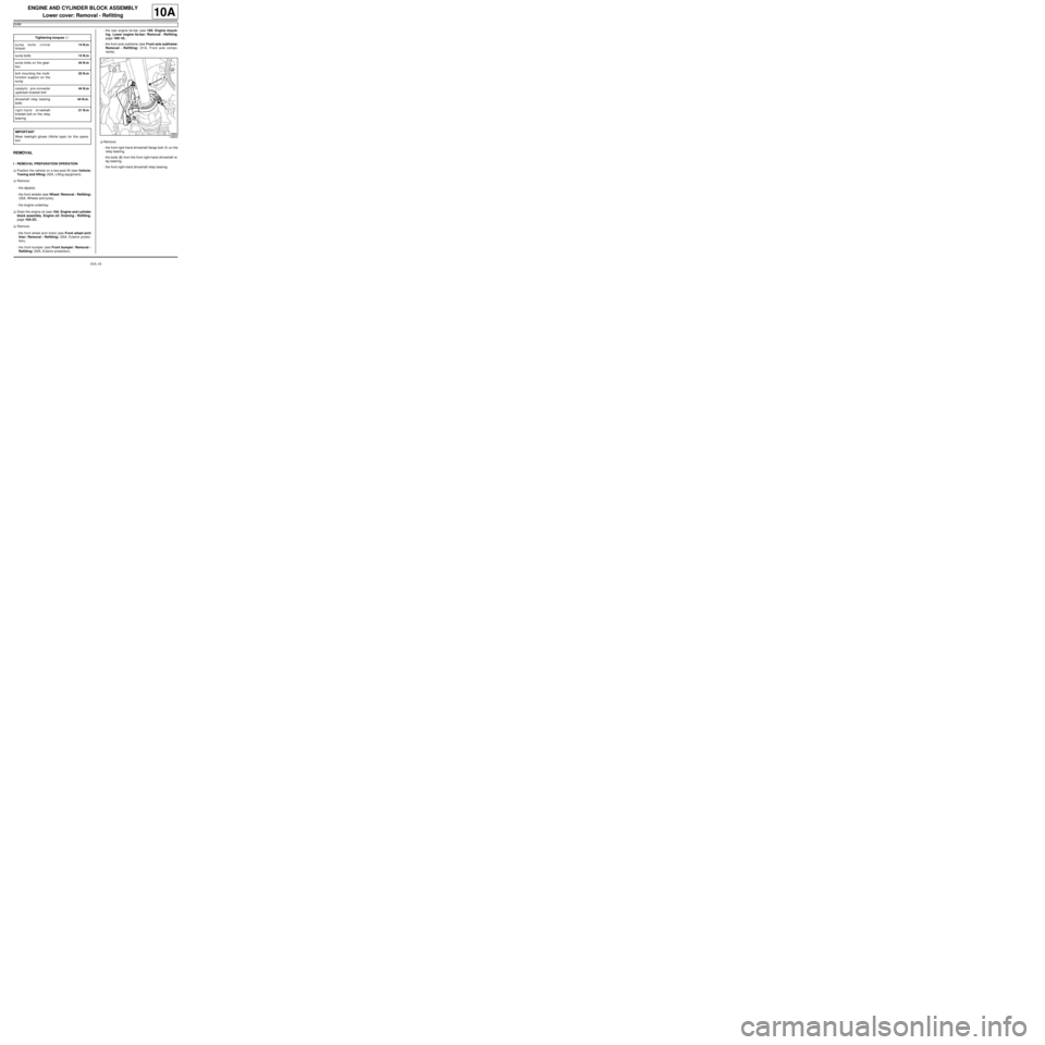
aRemove:
-the front right-hand driveshaft flange bolt (1) on the
relay bearing,
-the bolts (2) from the front right-hand driveshaft re-
lay bearing,
-the front right-hand driveshaft relay bearing. Tightening torquesm
sump bolts (initial
torque)14 N.m
sump bolts14 N.m
sump bolts on the gear-
box44 N.m
bolt mounting the multi-
function support on the
sump25 N.m
catalytic pre-converter
upstream bracket bolt44 N.m
driveshaft relay bearing
bolts44 N.m.
right-hand driveshaft
bracket bolt on the relay
bearing21 N.m
IMPORTANT
Wear leaktight gloves (Nitrile type) for this opera-
tion.
128800
Page 25 of 652
10A-19
ENGINE AND CYLINDER BLOCK ASSEMBLY
Lower cover: Removal - Refitting
K4M
10A
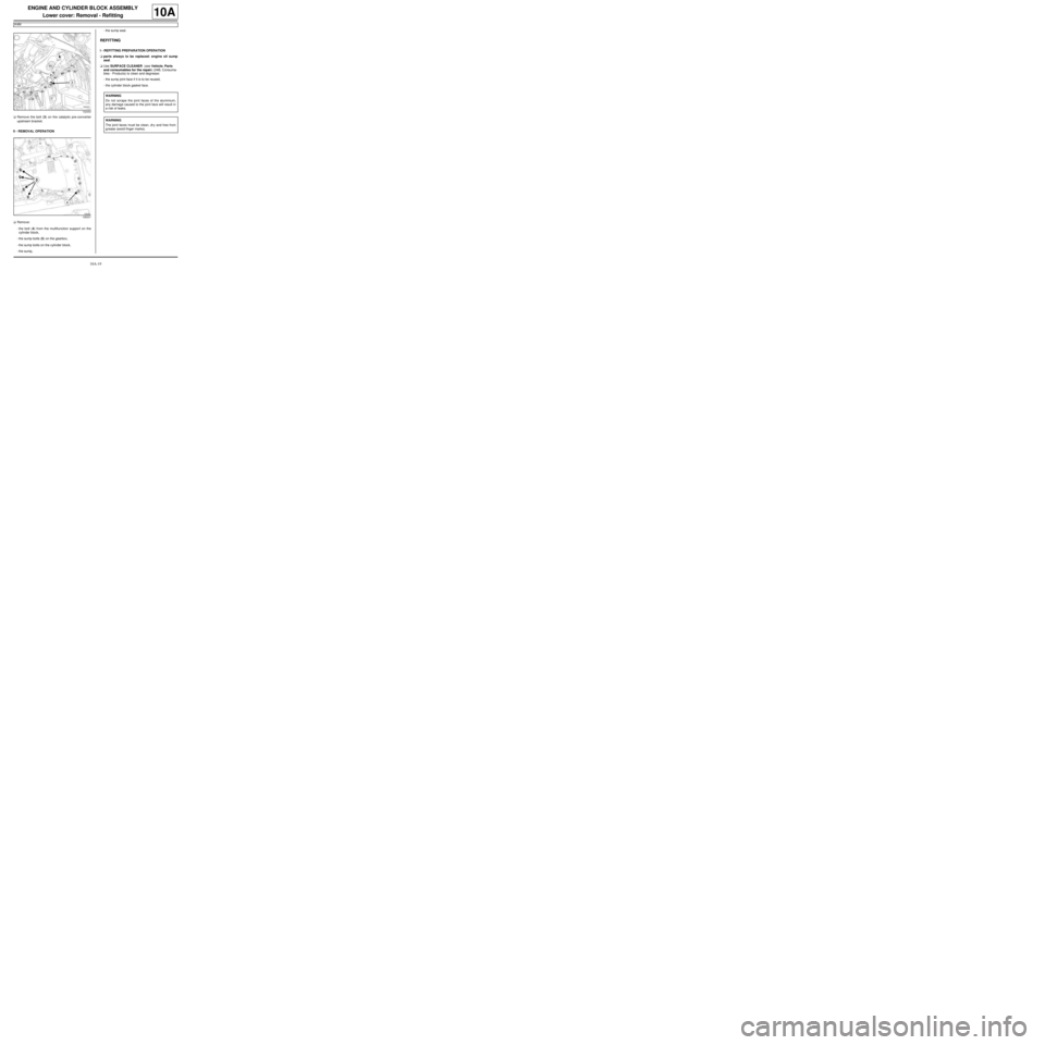
aRemove the bolt (3) on the catalytic pre-converter
upstream bracket.
II - REMOVAL OPERATION
aRemove:
-the bolt (4) from the multifunction support on the
cylinder block,
-the sump bolts (5) on the gearbox,
-the sump bolts on the cylinder block,
-the sump,-the sump seal.
REFITTING
I - REFITTING PREPARATION OPERATION
aparts always to be replaced: engine oil sump
seal.
aUse SURFACE CLEANER (see Vehicle: Parts
and consumables for the repair) (04B, Consuma-
bles - Products) to clean and degrease:
-the sump joint face if it is to be reused,
-the cylinder block gasket face.
132343
126231
WARNING
Do not scrape the joint faces of the aluminium,
any damage caused to the joint face will result in
a risk of leaks.
WARNING
The joint faces must be clean, dr y and free from
grease (avoid finger marks).
Page 26 of 652
10A-20
ENGINE AND CYLINDER BLOCK ASSEMBLY
Lower cover: Removal - Refitting
K4M
10A
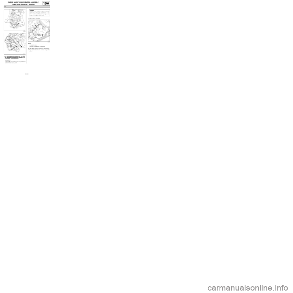
aUse SILICONE ADHESIVE SEALANT (see Vehi-
cle: Parts and consumables for the repair) (04B,
Consumables - Products) to apply:
-a bead at (4) ,
-a drop at (5) at the joint between the cylinder block
and crankshaft closure panel.II - REFITTING OPERATION
aRefit:
-a new sump seal,
-the sump in the direction of the arrows.
aFinger tighten the sump bolts on the cylinder block.
aFinger tighten the 4 sump bolts on the gearbox
housing.
20167
20166
WARNING
Applying excess sealant could cause it to be
squeezed out when parts are tightened. A mix-
ture of sealant and fluid could damage certain
components (engine, radiator, etc.).
145657
Page 27 of 652
10A-21
ENGINE AND CYLINDER BLOCK ASSEMBLY
Lower cover: Removal - Refitting
K4M
10A
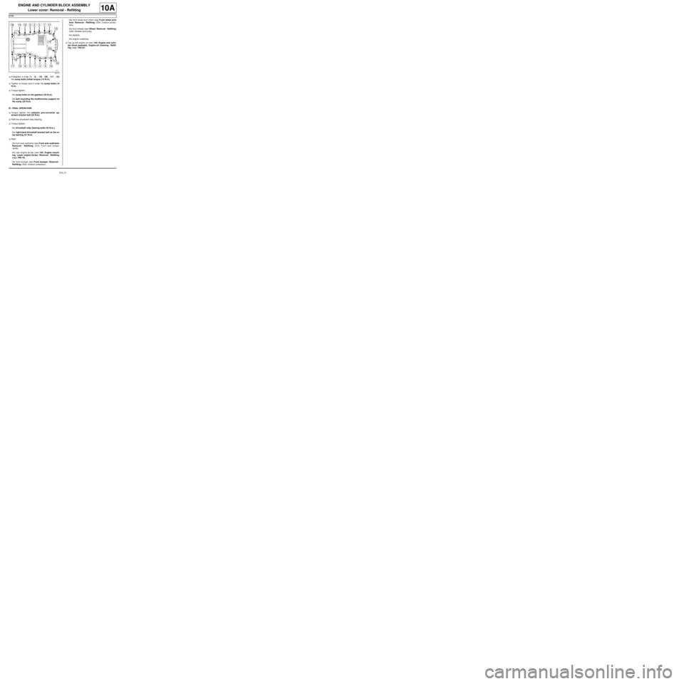
aPretighten in order (1) , (2) , (19) , (20) , (17) , (18)
the sump bolts (initial torque) (14 N.m).
aTighten to torque and in order the sump bolts (14
N.m).
aTorque tighten:
-the sump bolts on the gearbox (44 N.m),
-the bolt mounting the multifunction support on
the sump (25 N.m).
III - FINAL OPERATION
aTorque tighten the catalytic pre-converter up-
stream bracket bolt (44 N.m).
aRefit the driveshaft relay bearing.
aTorque tighten:
-the driveshaft relay bearing bolts (44 N.m.),
-the right-hand driveshaft bracket bolt on the re-
lay bearing (21 N.m).
aRefit:
-the front axle subframe (see Front axle subframe:
Removal - Refitting) (31A, Front axle compo-
nents),
-the rear engine tie-bar (see 19D, Engine mount-
ing, Lower engine tie-bar: Removal - Refitting,
page 19D-18) ,
-the front bumper (see Front bumper: Removal -
Refitting) (55A, Exterior protection),-the front wheel arch liners (see Front wheel arch
liner: Removal - Refitting) (55A, Exterior protec-
tion),
-the front wheels (see Wheel: Removal - Refitting)
(35A, Wheels and tyres),
-the dipstick,
-the engine undertray.
aTop up the engine oil (see 10A, Engine and cylin-
der block assembly, Engine oil: Draining - Refill-
ing, page 10A-22) .
20171
Page 31 of 652
10A-25
ENGINE AND CYLINDER BLOCK ASSEMBLY
Engine oil: Draining - Refilling
K4M
10A
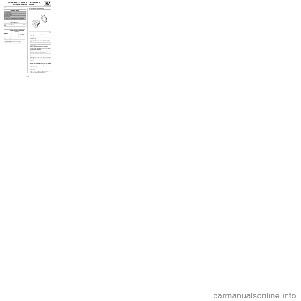
I - RECOMMENDATIONS FOR REPAIR
aDirection of fitting for a drain plug seal.For a sheet metal engine oil sump
aThere is no direction of fitting for a seal fitted with a
rubber lip.
II - PARTS AND CONSUMABLES FOR THE REPAIR
aparts always to be replaced: Drain plug seal on
engine oil sump.
aconsumable:
-engine oil (see Engine oil: Specifications) (Tech-
nical Note 6013A, 04A, Lubricants). Equipment required
oil recovery tray
oil change wrench
torque wrench
oil change end piece with an 8 mm square drive
Tightening torquesm
engine oil sump drain
plug20 N.m
EngineAverage oil capacity (adjust with
dipstick) (l)
DrainingOil change
plus oil filter
replacement
K4M4.9 5
113765
IMPORTANT
Wear leaktight gloves (Nitrile type) for this opera-
tion.
WARNING
Always check the oil level using the dipstick.
Do not exceed the maximum level on the dipstick
(could destroy the engine).
Correct the engine oil level if necessary before
delivering the vehicle to the customer.
Note:
When topping up the engine oil, always leave at
least 10 minutes before checking the level with a
dipstic k.