exhaust RENAULT TWINGO RS 2009 2.G Engine And Peripherals Repair Manual
[x] Cancel search | Manufacturer: RENAULT, Model Year: 2009, Model line: TWINGO RS, Model: RENAULT TWINGO RS 2009 2.GPages: 652
Page 333 of 652
12B-8
TURBOCHARGING
Turbocharger: Removal - Refitting
D4F, and 780 or 782
12B
REMOVAL
I - REMOVAL PREPARATION OPERATION
aPosition the vehicle on a two-post lift (see Vehicle:
Towing and lifting) (02A, Lifting equipment).
aDisconnect the battery (see Battery: Removal - Re-
fitting) (80A, Battery).
aRemove the engine undertray.
aDrain the manual gearbox (see Manual gearbox
oils: Draining - Filling) (21A, Manual gearbox).
aRemove:
-the air filter unit (see 12A, Fuel mixture, Air filter
unit: Removal - Refitting, page 12A-13) ,
-the upstream oxygen sensor (see 17B, Petrol in-
jection, Oxygen sensors: Removal - Refitting,
page 17B-13) ,
-the lower engine tie-bar (see 19D, Engine mount-
ing, Lower engine tie-bar: Removal - Refitting,
page 19D-18) ,
-the front right-hand wheel driveshaft (see Front
right-hand driveshaft: Removal - Refitting)
(29A, Driveshafts),
-the catalytic converter (see 19B, Exhaust, Cata-
lytic converter: Removal - Refitting, page 19B-
12) .II - OPERATION FOR REMOVAL OF PART
CONCERNED
aRemove the turbocharger oil return pipe (see 12B,
Turbocharging, Turbocharger oil pipe: Removal
- Refitting, page 12B-12) .
aFit the tools (Ms. 583) onto the turbocharger cooling
hoses (6) .
aRemove the turbocharger cooling hose clips using
the tool (Mot. 1448).
aDisconnect the turbocharger cooling hoses.
aRemove the turbocharger cooling pipe strut bolt (7) .
aRemove the turbocharger oil supply pipe (see 12B,
Turbocharging, Turbocharger oil pipe: Removal
- Refitting, page 12B-12) . Special tooling required
Ms. 583Pipe clamps .
Mot. 1448Remote operation pliers for
hose clips .
Tightening torquesm
turbocharger nuts21 N.m
turbocharger cooling
pipe hollow bolts30 N.m
turbocharger cooling
pipe bracket bolts10 N.m
IMPORTANT
Wear cut-resistant gloves during the operation.121773
Page 335 of 652
12B-10
TURBOCHARGING
Turbocharger: Removal - Refitting
D4F, and 780 or 782
12B
aLoosen the clip of the air filter unit air outlet pipe.
aRemove:
-the air outlet pipe of the air filter unit,
-the turbocharger cooling pipe bracket bolt,
-the turbocharger cooling hollow pipe bolts,
-the turbocharger cooling pipes.
REFITTING
I - REFITTING PREPARATION OPERATION
aparts always to be replaced: Turbocharger nut.
aparts always to be replaced: seal between ex-
haust manifold and turbocharger.
aparts always to be replaced: Turbocharger cool-
ant pipe if replacing the turbocharger.
aUse a SURFACE CLEANER (see Vehicle: Parts
and consumables for the repair) (04B, Consuma-
bles - Products) to clean and degrease the sealing
surfaces:
-of the turbocharger (if being reused),
-of the exhaust manifold.
II - REFITTING OPERATION FOR PART
CONCERNED
aRefit:
-a new turbocharger seal,
-the turbocharger,
-new turbocharger nuts.
aTorque tighten the turbocharger nuts (21 N.m).
1 - If replacing the turbocharger
aRefit:
-the turbocharger cooling pipes,
-the turbocharger cooling hollow pipe bolts,
-the turbocharger cooling pipe bracket bolts,-the air outlet pipe of the air filter unit.
aTighten the clip of the air outlet pipe on the air filter
unit.
aTorque tighten:
-the turbocharger cooling pipe hollow bolts (30
N.m),
-the turbocharger cooling pipe bracket bolts (10
N.m).
a
aConnect the turbocharging pressure regulation
pipes.
aClip on the clips of the turbocharging pressure regu-
lation pipes.
2 - If the turbocharger is not being replaced
aClip the wiring onto the turbocharger coolant rigid
pipe strut.
aConnect:
-the turbocharger discharge air pipe,
-the oil vapour recirculation pipe on the air filter unit
air outlet pipe,
-the petrol vapour recirculation pipe on the air filter
unit air outlet pipe,
-the turbocharging regulation solenoid valve con-
nector from the turbocharger,
-the ignition coil connector.
aTighten the turbocharger discharge air pipe clip.
aRefit the turbocharger oil supply pipe (see 12B, Tur-
bocharging, Turbocharger oil pipe: Removal -
Refitting, page 12B-12) .
aRefit the turbocharger cooling pipe strut bolt.
aConnect the turbocharger cooling hoses.
aFit the turbocharger cooling hose clips using the tool
(Mot. 1448).
aRemove the tools (Ms. 583).
aRefit the turbocharger oil return pipe (see 12B, Tur-
bocharging, Turbocharger oil pipe: Removal -
Refitting, page 12B-12) . WARNING
Ensure that no foreign bodies enter the turbine or
compressor during the refitting operation.
Check that the turbocharger oil return pipe is not
partially or completely blocked by scale. Check
that there are no leaks. If there are, replace the
part.Note:
Dur ing this operation, use a set of feeler gauges
to ensure that there is a minimum clearance of 3
mm between the turbocharger water outlet pipe
and the turbocharger heat shield.
Page 336 of 652
12B-11
TURBOCHARGING
Turbocharger: Removal - Refitting
D4F, and 780 or 782
12B
III - FINAL OPERATION
aRefit:
-the catalytic converter (see 19B, Exhaust, Cata-
lytic converter: Removal - Refitting, page 19B-
12) ,
-the front right-hand wheel driveshaft (see Front
right-hand driveshaft: Removal - Refitting)
(29A, Driveshafts),
-the lower engine tie-bar (see 19D, Engine mount-
ing, Lower engine tie-bar: Removal - Refitting,
page 19D-18) ,
-the upstream oxygen sensor (see 17B, Petrol in-
jection, Oxygen sensors: Removal - Refitting,
page 17B-13) ,
-the air filter unit (see 12A, Fuel mixture, Air filter
unit: Removal - Refitting, page 12A-13) .
aConnect the battery (see Battery: Removal - Refit-
ting) (80A, Battery).
aRefill:
-and bleed the cooling system (see 19A, Cooling,
Cooling system: Draining - Refilling, page 19A-
9) ,
-the manual gearbox (see Manual gearbox oils:
Draining - Filling) (21A, Manual gearbox).
aRefit the engine undertray.
Page 338 of 652
12B-13
TURBOCHARGING
Turbocharger oil pipe: Removal - Refitting
D4F, and 780 or 782
12B
a
aRemove the turbocharger air outlet pipe bolt (3) on
the throttle valve.
aUnclip the turbocharger air outlet pipe on the turbo-
charger in the direction of the arrow (4) .
aDisconnect the turbocharger air outlet pipe from theturbocharger.
aMove aside the turbocharger air outlet pipe.
aRemove the catalytic converter (see 19B, Exhaust,
Catalytic converter: Removal - Refitting, page
19B-12) .
II - OPERATION FOR REMOVAL OF PART
CONCERNED
aRemove:
-the lower bolts from the heat shield,
-the upper bolts from the heat shield,
-the heat shield.
1 - Oil supply pipe
aRemove:
-the bolt (6) from the turbocharger oil supply pipe on
the turbocharger,
-the bolt (7) on the turbocharger oil supply pipe on
the cylinder block,
-the turbocharger oil supply pipe bolt (8) ,
-the turbocharger oil supply pipe.
122834
122673
Note:
If the turbocharger air outlet pipe tightening clip
(1) is removed, the flexible rubber pipe (2) and
the tightening clip (1) must be replaced.
Note:
If the clip (5) is removed from the heat resistant
protector, the latter must be replaced.
120962
Page 339 of 652
12B-14
TURBOCHARGING
Turbocharger oil pipe: Removal - Refitting
D4F, and 780 or 782
12B
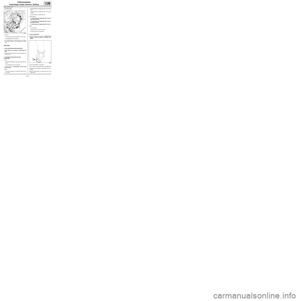
2 - Oil return pipe
aRemove:
-the bolts (9) from the turbocharger oil return pipe,
-the turbocharger oil return pipe.
aFit a blanking plug to the opening on the cylinder
block after removal of the turbocharger oil return
pipe.
REFITTING
I - REFITTING PREPARATION OPERATION
aparts always to be replaced: Turbocharger oil
pipe.
aRemove the protective plug from the opening on the
cylinder block.
II - REFITTING OPERATION FOR PART
CONCERNED
aRefit:
-the new turbocharger oil return pipe fitted with new
seals,
-the turbocharger oil return pipe bolts.
aTorque tighten the turbocharger oil return pipe
bolts (10 N.m).
aRefit:
-the new turbocharger oil supply pipe fitted with its
new seals,-the turbocharger oil supply pipe bolt on the cylinder
block,
-the turbocharger oil supply pipe bolt on the turbo-
charger,
-the turbocharger oil supply pipe bolt.
aTorque tighten:
-the turbocharger oil supply pipe bolt on the cyl-
inder block (19 N.m),
-the turbocharger oil supply pipe bolt on the tur-
bocharger (19 N.m),
-the turbocharger oil supply pipe bolt (10 N.m).
aRefit:
-the heat shield,
-the upper bolts from the heat shield,
-the lower bolts of the heat shield.
III - FINAL OPERATION
aRefit the catalytic converter (see 19B, Exhaust,
Catalytic converter: Removal - Refitting, page
19B-12) .
aFit the turbocharger air outlet pipe.
aPush the clip of the turbocharger air outlet pipe (10) .
aConnect the turbocharger air outlet pipe to the turbo-
charger.
aRefit the turbocharger air outlet pipe bolt on the
throttle valve.
120962
122666
Page 341 of 652
12B-16
TURBOCHARGING
Turbocharger oil pipe: Removal - Refitting
C44, and K9K
12B
REMOVAL
I - REMOVAL PREPARATION OPERATION
aPosition the vehicle on a two-post lift (see Vehicle:
Towing and lifting) (02A, Lifting equipment).
aRemove the front engine cover.
aDisconnect the battery (see Battery: Removal - Re-
fitting) (80A, Battery).
1 - Turbocharger oil supply pipe
aRemove:
-the windscreen wiper arms (see Windscreen wip-
er arm: Removal - Refitting) (85A, Wiping -
Washing),
-the scuttle panel grille (see Scuttle panel grille:
Removal - Refitting) (56A, Exterior equipment),
-the scoop under the scuttle panel grille (see Scoop
under the scuttle panel grille: Removal - Refit-
ting) (56A, Exterior equipment),
-the air filter box (see 12A, Fuel mixture, Air filter
unit: Removal - Refitting, page 12A-13) ,
-the exhaust gas recirculation solenoid valve (see
14A, Antipollution, Exhaust gas recirculation
solenoid valve: Removal - Refitting, page 14A-
10) .
2 - turbocharger oil return pipe
aRemove the catalytic converter (see 19B, Exhaust,
Catalytic converter: Removal - Refitting, page
19B-12) .II - OPERATION FOR REMOVAL OF PART
CONCERNED
1 - Turbocharger oil supply pipe
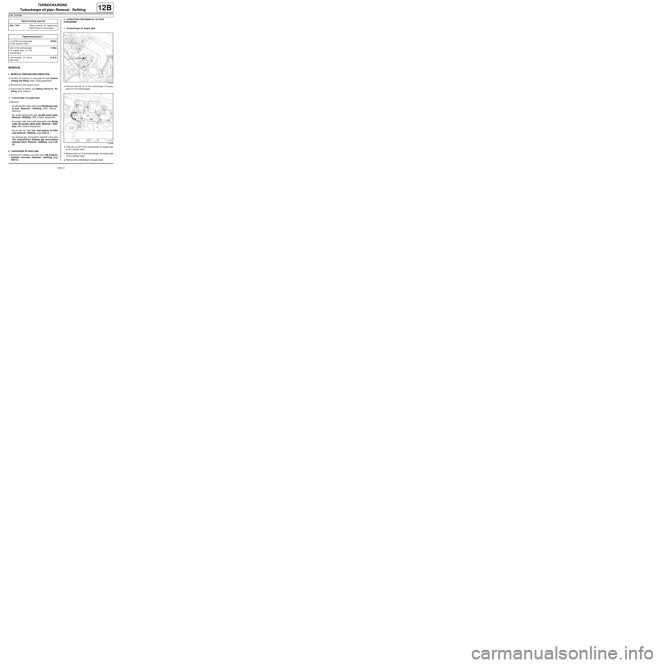
aRemove the bolt (1) of the turbocharger oil supply
pipe from the turbocharger.
aUndo the nut (2) of the turbocharger oil supply pipe
on the cylinder head.
aRemove the nut of the turbocharger oil supply pipe
on the cylinder head.
aRemove the turbocharger oil supply pipe. Special tooling required
Mot. 1746Offset wrench for tightening
High Pressure pump pipes.
Tightening torquesm
nut of the oil supply pipe
on the cylinder head35 Nm
bolt of the turbocharger
oil supply pipe on the
turbocharger14 Nm
turbocharger oil return
pipe bolts12 N.m
127900
127898
Page 342 of 652
12B-17
TURBOCHARGING
Turbocharger oil pipe: Removal - Refitting
C44, and K9K
12B
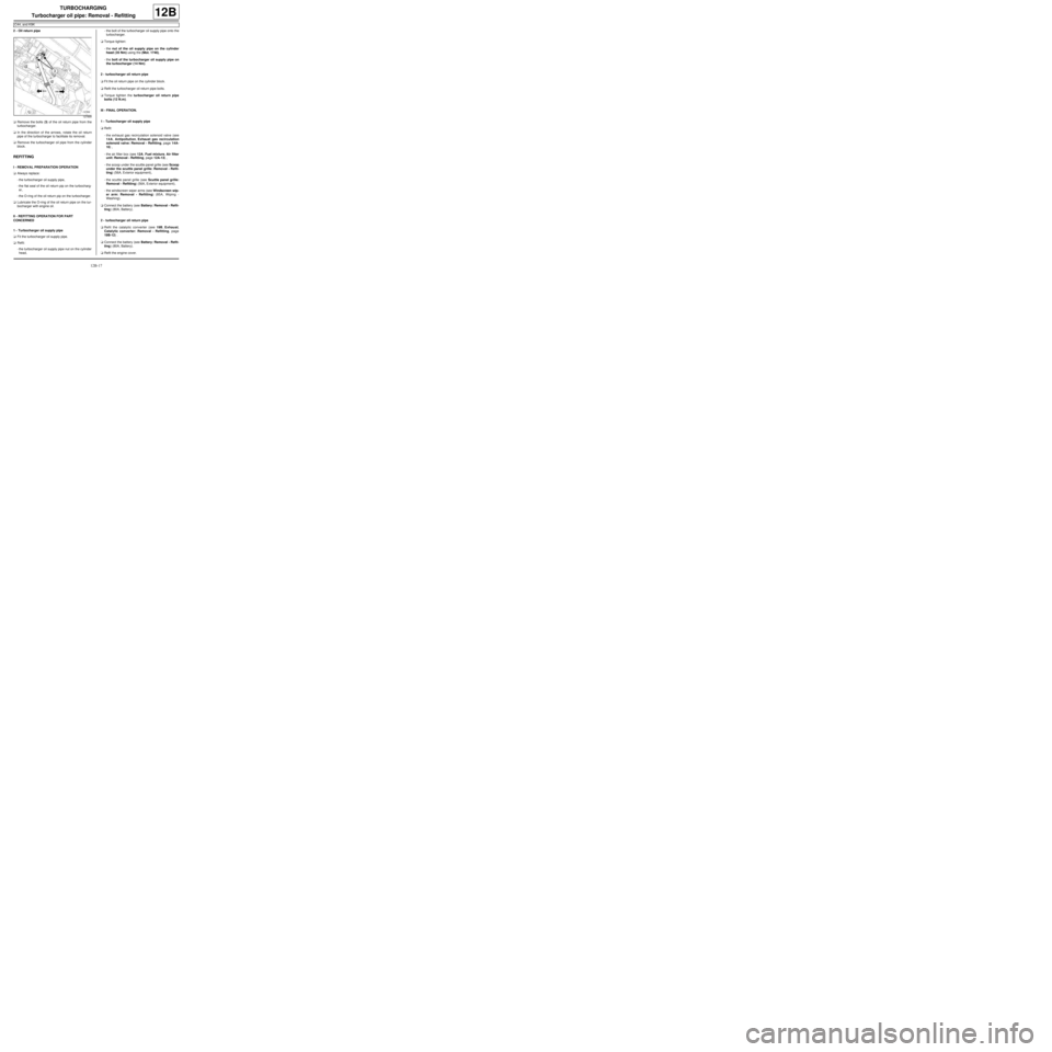
2 - Oil return pipe
aRemove the bolts (3) of the oil return pipe from the
turbocharger.
aIn the direction of the arrows, rotate the oil return
pipe of the turbocharger to facilitate its removal.
aRemove the turbocharger oil pipe from the cylinder
block.
REFITTING
I - REMOVAL PREPARATION OPERATION
aAlways replace:
-the turbocharger oil supply pipe,
-the flat seal of the oil return pip on the turbocharg-
er,
-the O-ring of the oil return pip on the turbocharger.
aLubricate the O-ring of the oil return pipe on the tur-
bocharger with engine oil.
II - REFITTING OPERATION FOR PART
CONCERNED
1 - Turbocharger oil supply pipe
aFit the turbocharger oil supply pipe.
aRefit:
-the turbocharger oil supply pipe nut on the cylinder
head,-the bolt of the turbocharger oil supply pipe onto the
turbocharger.
aTorque tighten:
-the nut of the oil supply pipe on the cylinder
head ( 35 Nm) using the (Mot. 1746),
-the bolt of the turbocharger oil supply pipe on
the turbocharger (14 Nm).
2 - turbocharger oil return pipe
aFit the oil return pipe on the cylinder block.
aRefit the turbocharger oil return pipe bolts.
aTorque tighten the turbocharger oil return pipe
bolts (12 N.m).
III - FINAL OPERATION.
1 - Turbocharger oil supply pipe
aRefit:
-the exhaust gas recirculation solenoid valve (see
14A, Antipollution, Exhaust gas recirculation
solenoid valve: Removal - Refitting, page 14A-
10) ,
-the air filter box (see 12A, Fuel mixture, Air filter
unit: Removal - Refitting, page 12A-13) ,
-the scoop under the scuttle panel grille (see Scoop
under the scuttle panel grille: Removal - Refit-
ting) (56A, Exterior equipment),
-the scuttle panel grille (see Scuttle panel grille:
Removal - Refitting) (56A, Exterior equipment),
-the windscreen wiper arms (see Windscreen wip-
er arm: Removal - Refitting) (85A, Wiping -
Washing).
aConnect the battery (see Battery: Removal - Refit-
ting) (80A, Battery).
2 - turbocharger oil return pipe
aRefit the catalytic converter (see 19B, Exhaust,
Catalytic converter: Removal - Refitting, page
19B-12) .
aConnect the battery (see Battery: Removal - Refit-
ting) (80A, Battery).
aRefit the engine cover.
127899
Page 370 of 652
13B-9
DIESEL INJECTION
Diesel injection: List and location of components
K9K, and 740
13B
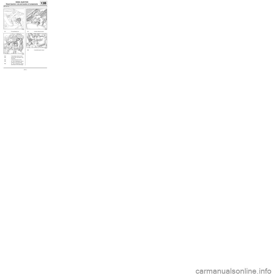
121436
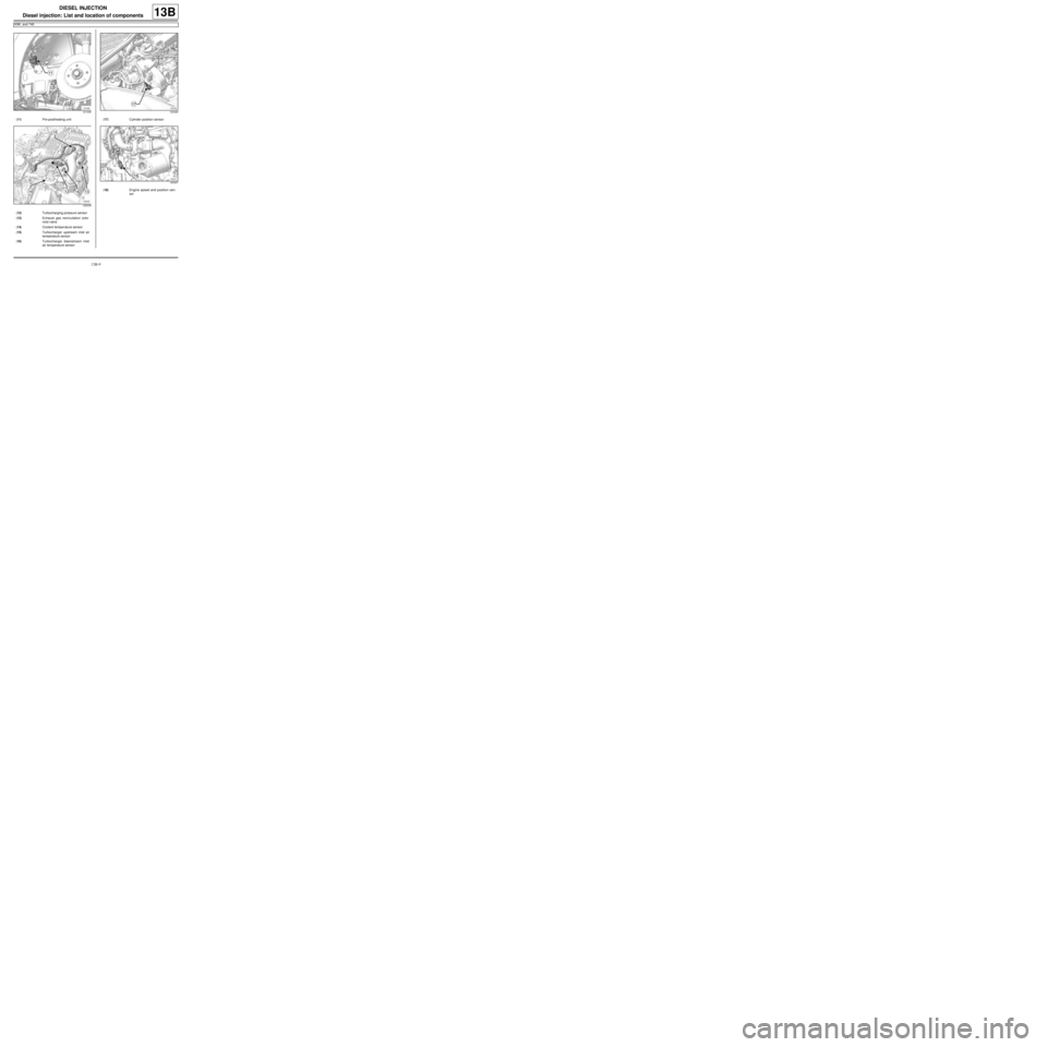
(11) Pre-postheating unit
120039
(12) Turbocharging pressure sensor
(13) Exhaust gas recirculation sole-
noid valve
(14) Coolant temper ature sensor
(15) Turbocharger upstream inlet air
temperature sensor
(16) Turbocharger downstream inlet
air temperature sensor
120326
(17) Cylinder position sensor
120327
(18) Engine speed and position sen-
sor
Page 372 of 652
13B-11
DIESEL INJECTION
Diesel injection: List and location of components
K9K, and 718
13B
141220
(11) Pre-postheating unit
120039
(12) Turbocharger pressure sensor
(13) Exhaust gas recirculation sole-
noid valve
(14) Coolant temper ature sensor
(15) Air inlet temperature sensor
upstream of the turbocharger
(16) Air inlet temperature sensor
downstream of the turbocharger
120326
(17) Cylinder reference sensor
120327
(18) Crankshaft position sensor
Page 428 of 652
14A-10
ANTIPOLLUTION
Exhaust gas recirculation solenoid valve: Removal - Refitting
K9K
14A
PARTS AND CONSUMABLES FOR THE
REPAIR WORK
aConsumables (see Vehicle: Parts and consuma-
bles for the repair) (02A, Parts and consumables):
-ABRASIVE PAD,
-SURFACE CLEANER.
REMOVAL
I - REMOVAL PREPARATION OPERATION
aRemove:
-the engine cover,
-the air filter box (see 12A, Fuel mixture, Air filter
unit: Removal - Refitting, page 12A-13) .
II - OPERATION FOR REMOVAL OF PART
CONCERNED
aRemove:
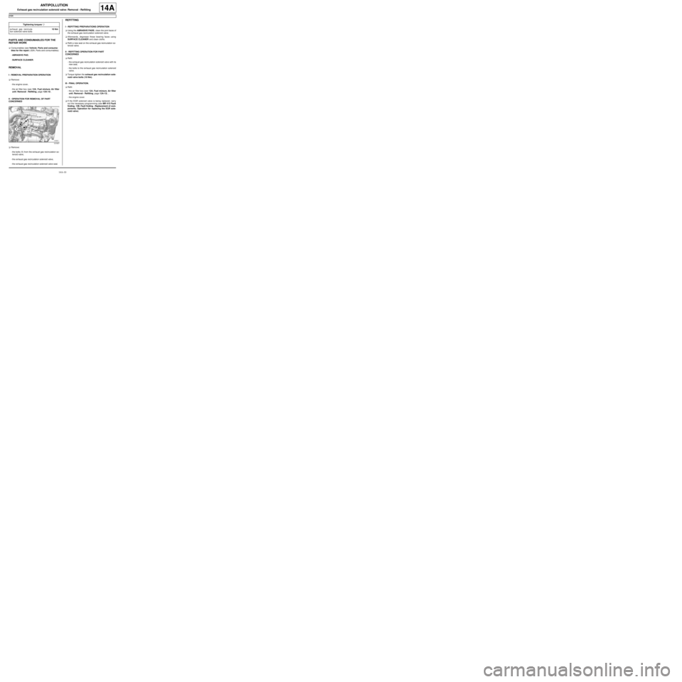
-the bolts (1) from the exhaust gas recirculation so-
lenoid valve,
-the exhaust gas recirculation solenoid valve,
-the exhaust gas recirculation solenoid valve seal.
REFITTING
I - REFITTING PREPARATIONS OPERATION
aUsing the ABRASIVE PADS, clean the joint faces of
the exhaust gas recirculation solenoid valve.
aAfterwards, degrease these bearing faces using
SURFACE CLEANER and clean cloths.
aRefit a new seal on the exhaust gas recirculation so-
lenoid valve.
II - REFITTING OPERATION FOR PART
CONCERNED
aRefit:
-the exhaust gas recirculation solenoid valve with its
new seal,
-the bolts to the exhaust gas recirculation solenoid
valve.
aTorque tighten the exhaust gas recirculation sole-
noid valve bolts (10 Nm).
III - FINAL OPERATION.
aRefit:
-the air filter box (see 12A, Fuel mixture, Air filter
unit: Removal - Refitting, page 12A-13) ,
-the engine cover.
aIf the EGR solenoid valve is being replaced, carry
out the necessary programming (see MR 413 Fault
finding, 13B, Fault finding - Replacement of com-
ponents, Operation for replacing the EGR sole-
noid valve). Tightening torquesm
exhaust gas recircula-
tion solenoid valve bolts10 Nm
121637