exhaust RENAULT TWINGO RS 2009 2.G Engine And Peripherals Manual PDF
[x] Cancel search | Manufacturer: RENAULT, Model Year: 2009, Model line: TWINGO RS, Model: RENAULT TWINGO RS 2009 2.GPages: 652
Page 439 of 652

14A-21
ANTIPOLLUTION
Exhaust gas recirculation rigid pipe: Removal - Refitting
K9K
14A
aRefit the exhaust gas recirculation rigid pipe with a
new clip.
aFit the rigid exhaust gas recirculation pipe bolts,
without tightening them.
aAdjust the rigid exhaust gas recirculation pipe in re-
lation to the exhaust gas recirculation assembly.
aTorque tighten the rigid exhaust gas recirculation
pipe clip (5 N.m).
aCheck that the rigid exhaust gas recirculation pipe is
not constrained.
aTorque tighten the bolts of the exhaust gas recir-
culation rigid pipe on the exhaust manifold (36
N.m).
III - FINAL OPERATION
aRefit:
-the catalytic converter (see 19B, Exhaust, Cata-
lytic converter: Removal - Refitting, page 19B-
12) ,
-the lower engine tie-bar (see 19D, Engine mount-
ing, Lower engine tie-bar: Removal - Refitting,
page 19D-18) ,
-the air filter unit (see 12A, Fuel mixture, Air filter
unit: Removal - Refitting, page 12A-13) ,
-the scoop under the scuttle panel grille (see Scoop
under the scuttle panel grille: Removal - Refit-
ting) (56A, Exterior equipment),
-the scuttle panel grille (see Scuttle panel grille:
Removal - Refitting) (56A, Exterior equipment),
-the windscreen wiper arms (see Windscreen wip-
er arm: Removal - Refitting) (85A, Wiping -
Washing),
-the engine cover.
aConnect the battery (see ) (80A, Battery). K9K, and 740
Page 490 of 652
17B-15
PETROL INJECTION
Oxygen sensors: Removal - Refitting
D4F, and 780 or 782
17B
REMOVAL
I - REMOVAL PREPARATION OPERATION
aPosition the vehicle on a two-post lift (see Vehicle:
Towing and lifting) (02A, Lifting equipment).
II - OPERATION FOR REMOVAL OF PART
CONCERNED
1 - Removing the upstream oxygen sensor
aRemove the air filter unit (see 12A, Fuel mixture,
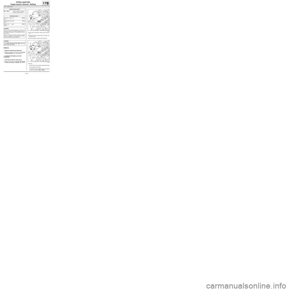
Air filter unit: Removal - Refitting, page 12A-13) .aDisconnect the upstream oxygen sensor connector
(1) .
aUnclip the upstream oxygen sensor connector from
the rocker cover.
aUnclip the upstream oxygen sensor wiring (2) .
aRemove:
-the bolts (3) from the exhaust manifold heat shield,
-the turbocharger heat shield,
-the upstream oxygen sensor (4) from the catalytic
converter using the tool (Mot. 1495-01). Special tooling required
Mot. 1495-0122 mm socket for removal -
refitting of oxygen sensors.
Tightening torquesm
upstream oxygen sen-
sor45 N.m
turbocharger heat shield
bolts8 N.m
downstream oxygen
sensor45 N.m
WARNING
Do not use any product designed to improve the
electr ical contact in the injection computer and oxy-
gen sensor connectors or on the bodies of the oxy-
gen sensors.
Failure to respect this advice causes the oxygen
sensor to malfunction and results in failure to com-
ply with the emission control standard.
WARNING
If the connections are corroded, repair the wiring
(see Wiring: Precautions for repair) (Technical
Note 6015A, 88A, Wiring).
120957
120957
Page 493 of 652

17B-18
PETROL INJECTION
Oxygen sensors: Removal - Refitting
K4M
17B
REFITTING THE UPSTREAM OXYGEN
SENSOR
I - REFITTING PREPARATION OPERATION
aClean the threading of the upstream oxygen sensor
using a WIRE BRUSH.
aUse SURFACE CLEANER (see Vehicle: Parts
and consumables for the repair) (04B, Consuma-
bles - Products) to clean and degrease:
-the thread hole of the upstream oxygen sensor on
the exhaust manifold,
-the threading of the upstream oxygen sensor if it is
to be reused.
II - REFITTING OPERATION
aRefit the upstream oxygen sensor.
aAngle tighten the upstream oxygen sensor ( 90˚).
aAttach the upstream oxygen sensor wiring.
aConnect the upstream oxygen sensor connector.III - FINAL OPERATION
aRefit:
-the engine undertray.
-the front right-hand wheel arch liner (see Front
wheel arch liner: Removal - Refitting) (55A, Ex-
terior protection),
-the front right-hand wheel (see Wheel: Removal -
Refitting) (35A, Wheels and tyres).
REMOVAL OF THE DOWNSTREAM
OXYGEN SENSOR
I - REMOVAL PREPARATION OPERATION
aDisconnect the battery (see ) (80A, Battery).
aRemove:
-the windscreen wiper arms (see Windscreen wip-
er arm: Removal - Refitting) (85A, Wiping -
Washing),
-the scuttle panel grille (see Scuttle panel grille:
Removal - Refitting) (56A, Exterior equipment),
-the scoop under the scuttle panel grille (see Scoop
under the scuttle panel grille: Removal - Refit-
ting) (56A, Exterior equipment).
132539
Note:
For angular tightening, make a mark (6) on the
catalytic pre-converter in the middle of the flat
surface of the upstream oxygen sensor. Move the
upstream oxygen sensor stop (7) to the mark (6)
.
Page 494 of 652

17B-19
PETROL INJECTION
Oxygen sensors: Removal - Refitting
K4M
17B
II - REMOVAL OPERATION
aDisconnect the downstream oxygen sensor connec-
tor (3) .
aUnclip the wiring from the downstream oxygen sen-
sor at (4) .
aRemove the downstream oxygen sensor (5) using
the tool (Mot. 1495).
REFITTING THE DOWNSTREAM OXYGEN
SENSOR
I - REFITTING PREPARATION OPERATION
aClean the threading of the downstream oxygen sen-
sor using a WIRE BRUSH.
aUse SURFACE CLEANER (see Vehicle: Parts
and consumables for the repair) (04B, Consuma-
bles - Products) to clean and degrease:
-the thread hole of the downstream oxygen sensor
on the exhaust manifold,
-the threading of the downstream oxygen sensor if it
is to be reused.
II - REFITTING OPERATION
aRefit the downstream oxygen sensor.
aTorque tighten the downstream oxygen sensor
(45 N.m) using the tool (Mot. 1495-01).
aClip on the downstream oxygen sensor wiring.
aConnect the downstream oxygen sensor connector.III - FINAL OPERATION
aRefit:
-the scoop under the scuttle panel grille (see Scoop
under the scuttle panel grille: Removal - Refit-
ting) (56A, Exterior equipment),
-the scuttle panel grille (see Scuttle panel grille:
Removal - Refitting) (56A, Exterior equipment),
-the windscreen wiper arms (see Windscreen wip-
er arm: Removal - Refitting) (85A, Wiping -
Washing).
aConnect the battery (see ) (80A, Battery).
132378
Page 583 of 652

19B-1
EXHAUST
Exhaust: List and location of components
19B
Page 584 of 652
19B-2
EXHAUST
Exhaust: List and location of components
19B
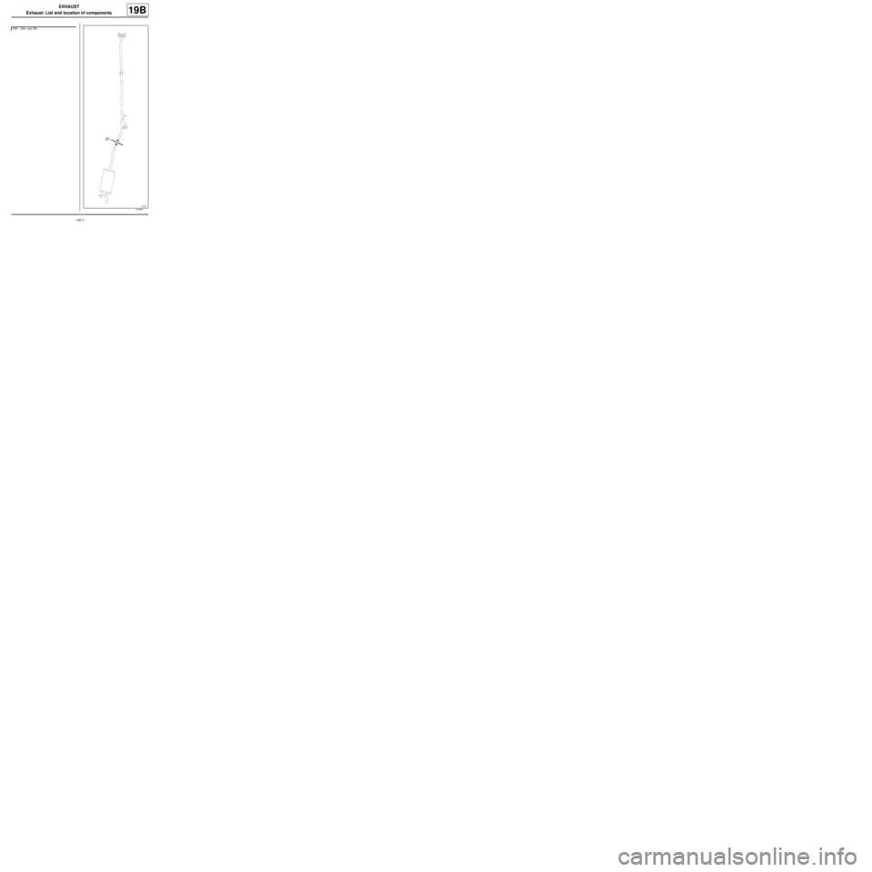
K9K – D4F, and 780
121642
Page 585 of 652

19B-3
EXHAUST
Exhaust: List and location of components
19B
(ZC) : Area to be cut
Page 586 of 652
19B-4
EXHAUST
Exhaust: List and location of components
19B
D4F, and 772 – D7F
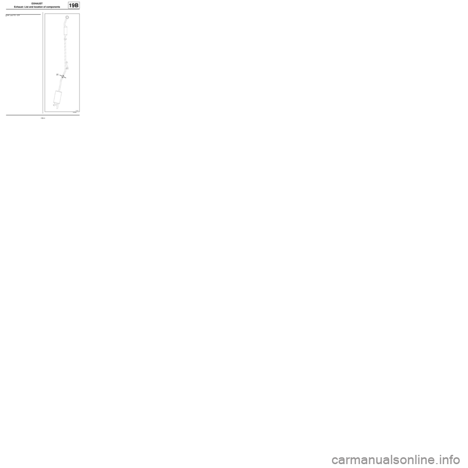
121641
Page 587 of 652

19B-5
EXHAUST
Exhaust: List and location of components
19B
(ZC) : Area to be cut
Page 588 of 652

19B-6
EXHAUST
Exhaust: List and location of components
19B
K4M
132480