exhaust RENAULT TWINGO RS 2009 2.G Engine And Peripherals Service Manual
[x] Cancel search | Manufacturer: RENAULT, Model Year: 2009, Model line: TWINGO RS, Model: RENAULT TWINGO RS 2009 2.GPages: 652
Page 320 of 652
12A-55
FUEL MIXTURE
Exhaust manifold: Removal - Refitting
K4M
12A
REMOVAL
I - REMOVAL PREPARATION OPERATION
aPosition the vehicle on a two-post lift (see Vehicle:
Towing and lifting) (02A, Lifting equipment).
aDisconnect the battery (see Battery: Removal - Re-
fitting) (80A, Battery).
aRemove:
-the engine undertray,
-the front right-hand wheel (see Wheel: Removal -
Refitting) (35A, Wheels and tyres),
-the windscreen wiper arms (see Windscreen wip-
er arm: Removal - Refitting) (85A, Wiping -
Washing),
-the scuttle panel grille (see Scuttle panel grille:
Removal - Refitting) (56A, Exterior equipment),
-the scoop under the scuttle panel grille (see Scoop
under the scuttle panel grille: Removal - Refit-
ting) (56A, Exterior equipment).
aDrain the gearbox (see Manual gearbox oils:
Draining - Filling) (21A, Manual gearbox).aRemove:
-the front right-hand wheel driveshaft (see Front
right-hand driveshaft: Removal - Refitting)
(29A, Driveshafts),
-the lower engine tie-bar (see 19D, Engine mount-
ing, Lower engine tie-bar: Removal - Refitting,
page 19D-18) ,
-the upstream expansion chamber (see 19B, Ex-
haust, Expansion chamber: Removal - Refit-
ting, page 19B-23) .
aRemove:
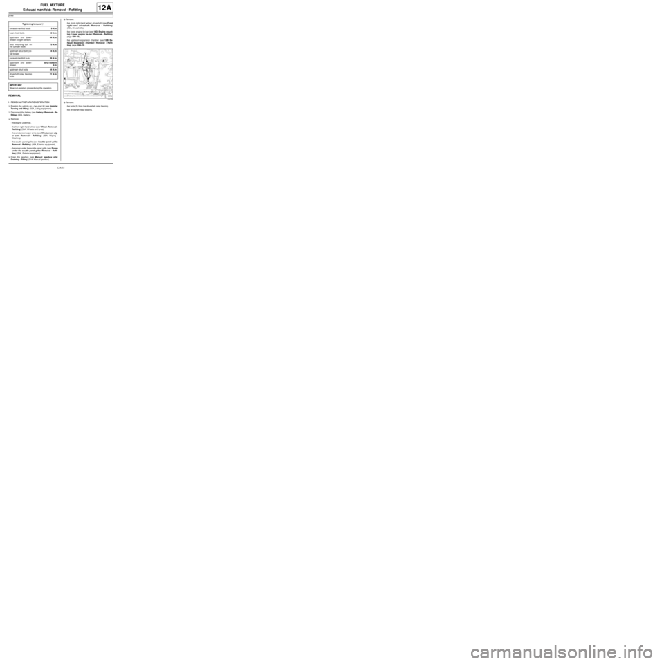
-the bolts (1) from the driveshaft relay bearing,
-the driveshaft relay bearing. Tightening torquesm
exhaust manifold studs9 N.m
heat shield bolts12 N.m
upstream and down-
stream oxygen sensors44 N.m
strut mounting bolt on
the cylinder block75 N.m
upstream strut bolt (ini-
tial torque)14 N.m
exhaust manifold nuts26 N.m
upstream and down-
streamstrut bolts44
N.m
upstream strut bolts44 N.m
driveshaft relay bearing
bolts21 N.m
IMPORTANT
Wear cut-resistant gloves during the operation.
131770
Page 321 of 652
12A-56
FUEL MIXTURE
Exhaust manifold: Removal - Refitting
K4M
12A
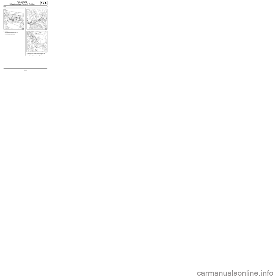
aRemove:
-the bulkhead heat shield bolts (2) ,
-the bulkhead heat shields.
aDisconnect the oxygen sensor connectors (3) .
aUnclip the oxygen sensor wiring at (4) .
132436132373
132378
Page 322 of 652
12A-57
FUEL MIXTURE
Exhaust manifold: Removal - Refitting
K4M
12A
II - REMOVAL OPERATION
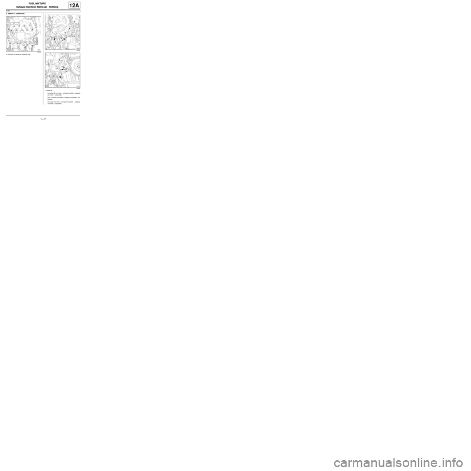
aRemove the exhaust manifold nuts.
aRemove:
-the bolts (5) from the « exhaust manifold - catalytic
converter » assembly,
-the « exhaust manifold - catalytic converter » as-
sembly,
-the seal from the « exhaust manifold - catalytic
converter » assembly.
132379
132392
132360
Page 323 of 652
12A-58
FUEL MIXTURE
Exhaust manifold: Removal - Refitting
K4M
12A
If replacing the « exhaust manifold - catalytic
converter » assembly
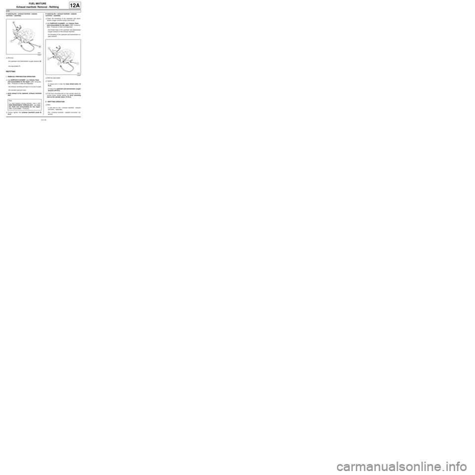
aRemove:
-the upstream and downstream oxygen sensors (6)
,
-the heat shield (7) .
REFITTING
I - REMOVAL PREPARATION OPERATION
aUse SURFACE CLEANER (see Vehicle: Parts
and consumables for the repair) (04B, Consuma-
bles - Products) to clean and degrease:
-the exhaust manifold joint face if it is to be re-used,
-the cylinder head joint face.
aparts always to be replaced: exhaust manifold
seal.
aTorque tighten the exhaust manifold studs (9
N.m).If replacing the « exhaust manifold - catalytic
converter » assembly
aClean the threading of the upstream and down-
stream oxygen sensors using a wire brush.
aUse SURFACE CLEANER (see Vehicle: Parts
and consumables for the repair) (04B, Consuma-
bles - Products) to clean and degrease:
-the thread holes of the upstream and downstream
oxygen sensors on the exhaust manifold,
-the threading of the upstream and downstream ox-
ygen sensors.
aRefit the heat shield.
aTighten:
-to torque and in order the heat shield bolts (12
N.m),
-to torque the upstream and downstream oxygen
sensors ( 44 N.m).
aIf the strut mounting bolt on the cylinder block be-
comes loose, torque tighten the strut mounting
bolt on the cylinder block ( 75 N.m).
II - REFITTING OPERATION
aRefit:
-a new seal on the « exhaust manifold - catalytic
converter » assembly,
-the « exhaust manifold - catalytic converter » as-
sembly.
132441
Note:
If a stud loosens during removal, coat it with
HIGH RESISTANCE THREADLOCK (see Vehi-
cle: Parts and consumables for the repair)
(04B, Consumables - Products).
132441
Page 324 of 652
12A-59
FUEL MIXTURE
Exhaust manifold: Removal - Refitting
K4M
12A
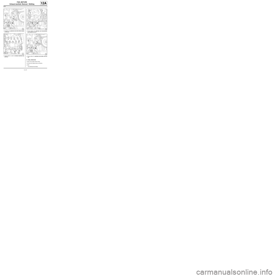
aPretighten the upstream strut bolt (initial torque)
(14 N.m) (8) .
aTorque tighten in order the exhaust manifold nuts
(26 N.m).aTorque tighten the upstream and downstream
(strut bolts44 N.m) (9) .
aTorque tighten the upstream strut bolts (44 N.m)
(10) .
III - FINAL OPERATION
aClip on the oxygen sensor wiring.
aConnect the oxygen sensor connectors.
aRefit:
-the bulkhead heat shields,
132360
132379132392
132360
Page 325 of 652
12A-60
FUEL MIXTURE
Exhaust manifold: Removal - Refitting
K4M
12A
-the driveshaft relay bearing.
aTorque tighten the driveshaft relay bearing bolts
(21 N.m).
aRefit:
-the upstream expansion chamber (see 19B, Ex-
haust, Expansion chamber: Removal - Refit-
ting, page 19B-23) ,
-the lower engine tie-bar (see 19D, Engine mount-
ing, Lower engine tie-bar: Removal - Refitting,
page 19D-18) ,
-the front right-hand wheel driveshaft (see Front
right-hand driveshaft: Removal - Refitting)
(29A, Driveshafts).
aFill the gearbox (see Manual gearbox oils: Drain-
ing - Filling) (21A, Manual gearbox).
aRefit:
-the scoop under the scuttle panel grille (see Scoop
under the scuttle panel grille: Removal - Refit-
ting) (56A, Exterior equipment),
-the scuttle panel grille (see Scuttle panel grille:
Removal - Refitting) (56A, Exterior equipment),
-the windscreen wiper arms (see Windscreen wip-
er arm: Removal - Refitting) (85A, Wiping -
Washing),
-the front right-hand wheel (see Wheel: Removal -
Refitting) (35A, Wheels and tyres),
-the engine undertray.
aConnect the battery (see Battery: Removal - Refit-
ting) (80A, Battery).
Page 326 of 652
12B-1
TURBOCHARGING
Turbocharging: Precautions for the repair
D4F or K9K
12B
I - TURBOCHARGER: GENERAL INSTRUCTIONS
For the turbocharging pressure regulator check (see
Fault finding - Tests) (Technical Note 3419A, 12B,
Turbocharging).
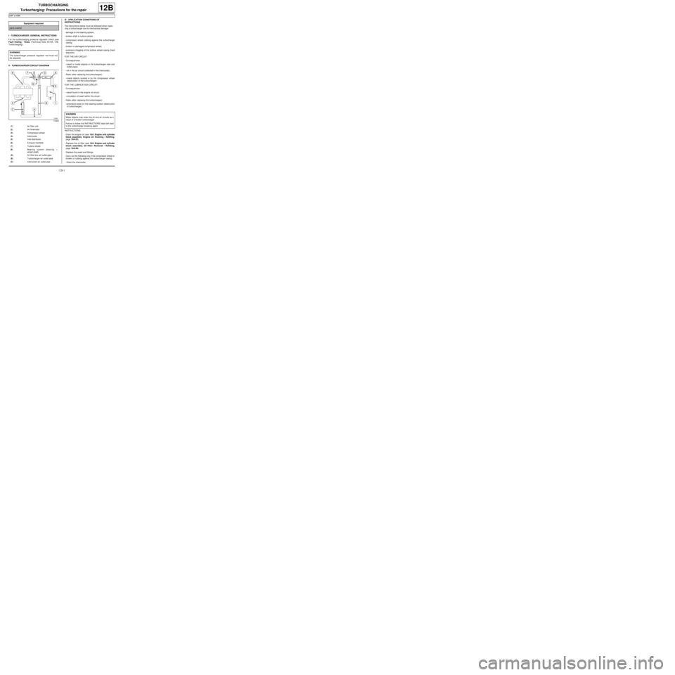
II - TURBOCHARGER CIRCUIT DIAGRAMIII - APPLICATION CONDITIONS OF
INSTRUCTIONS
The instructions below must be followed when repla-
cing a turbocharger due to mechanical damage:
-damage to the bearing system,
-broken shaft or turbine wheel,
-compressor wheel rubbing against the turbocharger
casing,
-broken or damaged compressor wheel,
-extensive clogging of the turbine wheel casing (hard
deposits).
FOR THE AIR CIRCUIT:
-Consequences:
•swarf or metal objects in the turbocharger inlet and
outlet pipes,
•oil in the air circuit (collected in the intercooler).
-Risks (after replacing the turbocharger):
•metal objects sucked in by the compressor wheel
(destruction of the turbocharger).
FOR THE LUBRICATION CIRCUIT:
-Consequences:
•swarf found in the engine oil circuit,
•circulation of swarf within the circuit.
-Risks (after replacing the turbocharger):
•premature wear on the bearing system (destruction
of turbocharger).
INSTRUCTIONS:
-Drain the engine oil (see 10A, Engine and cylinder
block assembly, Engine oil: Draining - Refilling,
page 10A-22)
-Replace the oil filter (see 10A, Engine and cylinder
block assembly, Oil filter: Removal - Refitting,
page 10A-29) .
-Replace the seals and fittings,
-Carry out the following only if the compressor wheel is
broken or rubbing against the turbocharger casing:
•Drain the intercooler, Equipment required
par ts washer
WARNING
The turbocharger pressure regulator rod must not
be adjusted.
112666
(1) Air filter unit
(2) Air flowmeter
(3) Compressor wheel
(4) Intercooler
(5) Inlet distributor
(6) Exhaust manifold
(7) Turbine wheel
(8) Bearing system (bearing +
wheel shaft)
(A) Air filter box air outlet pipe
(B) Turbocharger air outlet pipe
(C) Intercooler air outlet pipe
WARNING
Metal objects may enter the oil and air circuits as a
result of a broken turbocharger.
Failure to follow the INSTRUCTIONS listed will lead
to the turbocharger breaking again.
Page 329 of 652
12B-4
TURBOCHARGING
Turbocharger: Removal - Refitting
K9K
12B
REMOVAL
I - REMOVAL PREPARATION OPERATION
aPosition the vehicle on a two-post lift (see Vehicle:
Towing and lifting) (02A, Lifting equipment).
aDisconnect the battery (see ) (80A, Battery).
aRemove:
-the engine cover,
-the windscreen wiper arms (see Windscreen wip-
er arm: Removal - Refitting) (85A, Wiping -
Washing),
-the scuttle panel grille (see Scuttle panel grille:
Removal - Refitting) (56A, Exterior equipment),
-the scoop under the scuttle panel grille (see Scoop
under the scuttle panel grille: Removal - Refit-
ting) (56A, Exterior equipment),
-the air filter unit (see 12A, Fuel mixture, Air filter
unit: Removal - Refitting, page 12A-13) ,
-the EGR solenoid valve (see 14A, Antipollution,
Exhaust gas recirculation solenoid valve: Re-
moval - Refitting, page 14A-10) ,
-the lower engine tie-bar (see 19D, Engine mount-
ing, Lower engine tie-bar: Removal - Refitting,
page 19D-18) ,
-the catalytic converter (see 19B, Exhaust, Cata-
lytic converter: Removal - Refitting, page 19B-
12) .II - OPERATION FOR REMOVAL OF PART
CONCERNED
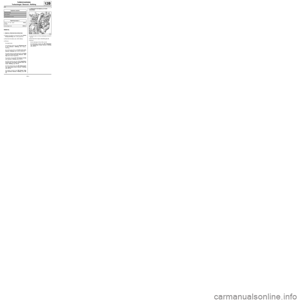
aLoosen the clip (1) of the air outlet pipe on the air fil-
ter unit.
aDisconnect the oil vapour rebreathing pipe (2) .
aRemove:
-the air outlet pipe of the air filter unit (3) ,
-the turbocharger oil pipes (see 12B, Turbocharg-
ing, Turbocharger oil pipe: Removal - Refitting,
page 12B-12) . Equipment required
cleaning trough
par ts washer
compressed air nozzle
Tightening torquesm
studs on the turbo-
charger9 N.m
turbocharger nuts28 N.m
121633
Page 331 of 652
12B-6
TURBOCHARGING
Turbocharger: Removal - Refitting
K9K
12B
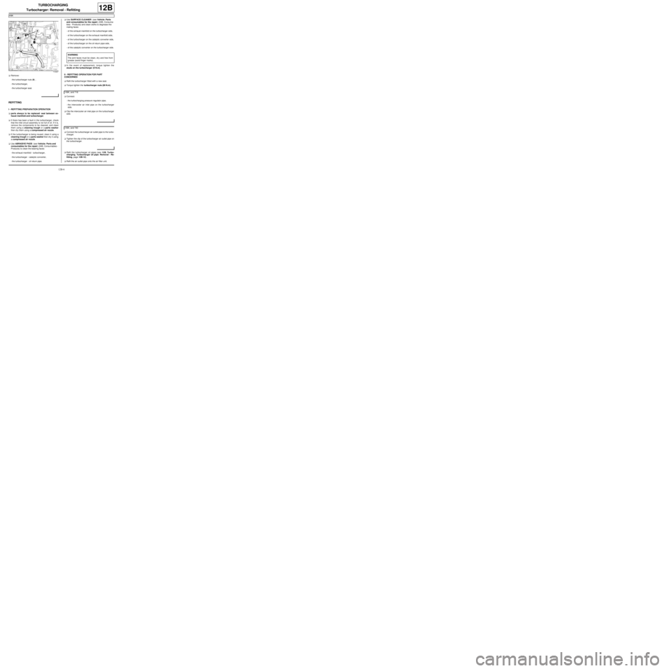
aRemove:
-the turbocharger nuts (8) ,
-the turbocharger,
-the turbocharger seal.
REFITTING
I - REFITTING PREPARATION OPERATION
aparts always to be replaced: seal between ex-
haust manifold and turbocharger.
aIf there has been a fault in the turbocharger, check
that the inlet circuit assembly is not full of oil. If it is,
remove the components to be cleaned, and clean
them using a cleaning trough or a parts washer
then dry them using a compressed air nozzle.
aIf the turbocharger is being reused, clean it using a
cleaning trough or a parts washer then dry it using
a compressed air nozzle.
aUse ABRASIVE PADS (see Vehicle: Parts and
consumables for the repair) (04B, Consumables -
Products) to clean the bearing faces:
-the exhaust manifold - turbocharger,
-the turbocharger - catalytic converter,
-the turbocharger - oil return pipe.aUse SURFACE CLEANER (see Vehicle: Parts
and consumables for the repair) (04B, Consuma-
bles - Products) and clean cloths to degrease the
mating faces:
-of the exhaust manifold on the turbocharger side,
-of the turbocharger on the exhaust manifold side,
-of the turbocharger on the catalytic converter side,
-of the turbocharger on the oil return pipe side,
-of the catalytic converter on the turbocharger side.
aIn the event of replacement, torque tighten the
studs on the turbocharger (9 N.m).
II - REFITTING OPERATION FOR PART
CONCERNED
aRefit the turbocharger fitted with a new seal.
aTorque tighten the turbocharger nuts (28 N.m).
aConnect:
-the turbocharging pressure regulator pipe,
-the intercooler air inlet pipe on the turbocharger
side.
aClip the intercooler air inlet pipe on the turbocharger
side.
aConnect the turbocharger air outlet pipe to the turbo-
charger.
aTighten the clip of the turbocharger air outlet pipe on
the turbocharger.
aRefit the turbocharger oil pipes (see 12B, Turbo-
charging, Turbocharger oil pipe: Removal - Re-
fitting, page 12B-12) .
aRefit the air outlet pipe onto the air filter unit.
112327
WARNING
The joint faces must be clean, dr y and free from
grease (avoid finger marks).
K9K, and 718
K9K, and 740
Page 332 of 652
12B-7
TURBOCHARGING
Turbocharger: Removal - Refitting
K9K
12B
III - FINAL OPERATION
aRefit:
-the catalytic converter (see 19B, Exhaust, Cata-
lytic converter: Removal - Refitting, page 19B-
12) ,
-the lower engine tie-bar (see 19D, Engine mount-
ing, Lower engine tie-bar: Removal - Refitting,
page 19D-18) ,
-the EGR solenoid valve (see 14A, Antipollution,
Exhaust gas recirculation solenoid valve: Re-
moval - Refitting, page 14A-10) ,
-the air filter unit (see 12A, Fuel mixture, Air filter
unit: Removal - Refitting, page 12A-13) ,
-the scoop under the scuttle panel grille (see Scoop
under the scuttle panel grille: Removal - Refit-
ting) (56A, Exterior equipment),
-the scuttle panel grille (see Scuttle panel grille:
Removal - Refitting) (56A, Exterior equipment),
-the windscreen wiper arms (see Windscreen wip-
er arm: Removal - Refitting) (85A, Wiping -
Washing),
-the engine cover.
aConnect the battery (see ) (80A, Battery).