battery RENAULT TWINGO RS 2009 2.G Engine And Peripherals Manual Online
[x] Cancel search | Manufacturer: RENAULT, Model Year: 2009, Model line: TWINGO RS, Model: RENAULT TWINGO RS 2009 2.GPages: 652
Page 258 of 652
11A-141
TOP AND FRONT OF ENGINE
Camshaft seal, timing end: Removal - Refitting
K4M
11A
REMOVAL
I - REMOVAL PREPARATION OPERATION
aPosition the vehicle on a two-post lift (see Vehicle:
Towing and lifting) (02A, Lifting equipment).
aDisconnect the battery (see Battery: Removal - Re-
fitting) (80A, Battery).
aRemove:
-the engine undertray,
-the front right-hand wheel (see Wheel: Removal -
Refitting) (35A, Wheels and tyres),
-the front right-hand wheel arch liner (see Front
wheel arch liner: Removal - Refitting) (55A, Ex-
terior protection),
-the front bumper (see Front bumper: Removal -
Refitting) (55A, Exterior protection),
-the headlights (see Halogen headlight: Removal
- Refitting) (80B, Headlights),
-the bonnet catch (see Bonnet lock: Removal -
Refitting) (52A, Non-side opening element mecha-
nisms),
-the front upper cross member (see Front upper
cross member: Removal - Refitting) (42A, Upper
front structure),
-the accessories belt (see 11A, Top and front of
engine, Accessories belt: Removal - Refitting,
page 11A-3) ,
-the air filter unit (see 12A, Fuel mixture, Air filter
unit: Removal - Refitting, page 12A-13) ,
-the throttle valve (see 12A, Fuel mixture, Throttle
valve: Removal - Refitting, page 12A-20) ,
-the windscreen wiper arms (see Windscreen wip-
er arm: Removal - Refitting) (85A, Wiping -
Washing),
-the scuttle panel grille (see Scuttle panel grille:
Removal - Refitting) (56A, Exterior equipment),
-the scoop under the scuttle panel grille (see Scoop
under the scuttle panel grille: Removal - Refit-
ting) (56A, Exterior equipment),-the right-hand suspended engine mounting (see
19D, Engine mounting, Right-hand suspended
engine mounting: Removal - Refitting, page
19D-13) ,
-the crankshaft accessories pulley (see 11A, Top
and front of engine, Crankshaft accessories
pulley: Removal - Refitting, page 11A-20) ,
-the timing belt (see 11A, Top and front of engine,
Timing belt: Removal - Refitting, page 11A-27) ,
-the camshaft dephaser (see 11A, Top and front of
engine, Camshaft dephaser: Removal - Refit-
ting, page 11A-135) .
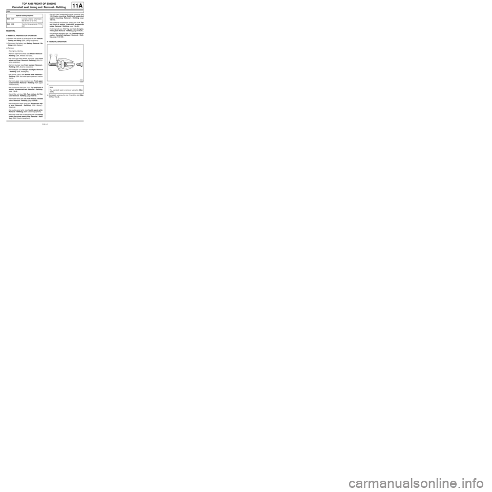
II - REMOVAL OPERATION
a
aCompletely unscrew the nut (1) and the bolt (Mot.
1577) of the (2) . Special tooling required
Mot. 1577Lip seal e xtractor (shaft diam-
eter 28 mm to 42 mm).
Mot. 1632Tool for fitting camshaft PTFE
seal
105257
Note:
The camshaft seal is removed using the (Mot.
1577).
Page 262 of 652

11A-145
TOP AND FRONT OF ENGINE
Camshaft seal, timing end: Removal - Refitting
K4M
11A
aFit the cover (13) and the collar nut (14) of the (Mot.
1632).
aScrew on the collar nut until the cover touches the
cylinder head.
aRemove:
-the collar nut from the (Mot. 1632),
-the cover from the (Mot. 1632),
-the stud from the (Mot. 1632).
III - FINAL OPERATION
aRefit:
-the camshaft dephaser (see 11A, Top and front of
engine, Camshaft dephaser: Removal - Refit-
ting, page 11A-135) ,
-the timing belt (see 11A, Top and front of engine,
Timing belt: Removal - Refitting, page 11A-27) ,
-the right-hand suspended engine mounting (see
19D, Engine mounting, Right-hand suspended
engine mounting: Removal - Refitting, page
19D-13) ,
-the scoop under the scuttle panel grille (see Scoop
under the scuttle panel grille: Removal - Refit-
ting) (56A, Exterior equipment),
-the scuttle panel grille (see Scuttle panel grille:
Removal - Refitting) (56A, Exterior equipment),
-the windscreen wiper arms (see Windscreen wip-
er arm: Removal - Refitting) (85A, Wiping -
Washing),-the throttle valve (see 12A, Fuel mixture, Throttle
valve: Removal - Refitting, page 12A-20) ,
-the air filter unit (see 12A, Fuel mixture, Air filter
unit: Removal - Refitting, page 12A-13) ,
-the accessories belt (see 11A, Top and front of
engine, Accessories belt: Removal - Refitting,
page 11A-3) ,
-the front upper cross member (see Front upper
cross member: Removal - Refitting) (42A, Upper
front structure),
-the bonnet catch (see Bonnet lock: Removal -
Refitting) (52A, Non-side opening element mecha-
nisms),
-the headlights (see Halogen headlight: Removal
- Refitting) (80B, Headlights),
-the front bumper (see Front bumper: Removal -
Refitting) (55A, Exterior protection),
-the front right-hand wheel arch liner (see Front
wheel arch liner: Removal - Refitting) (55A, Ex-
terior protection),
-the front right-hand wheel (see Wheel: Removal -
Refitting) (35A, Wheels and tyres),
-the engine undertray.
aConnect the battery (see Battery: Removal - Refit-
ting) (80A, Battery).
126222
Page 264 of 652
11A-147
TOP AND FRONT OF ENGINE
Oil decanter: Removal - Refitting
K4M
11A
REMOVAL
I - REMOVAL PREPARATION OPERATION
aDisconnect the battery (see ) (80A, Battery).
aRemove:
-the windscreen wiper arms (see Windscreen wip-
er arm: Removal - Refitting) (85A, Wiping -
Washing),
-the scuttle panel grille (see Scuttle panel grille:
Removal - Refitting) (56A, Exterior equipment),
-the scoop under the scuttle panel grille (see Scoop
under the scuttle panel grille: Removal - Refit-
ting) (56A, Exterior equipment),
-the inlet distributor (see 12A, Fuel mixture, Inlet
distributor: Removal - Refitting, page 12A-29) .
II - OPERATION FOR REMOVAL OF PART
CONCERNED
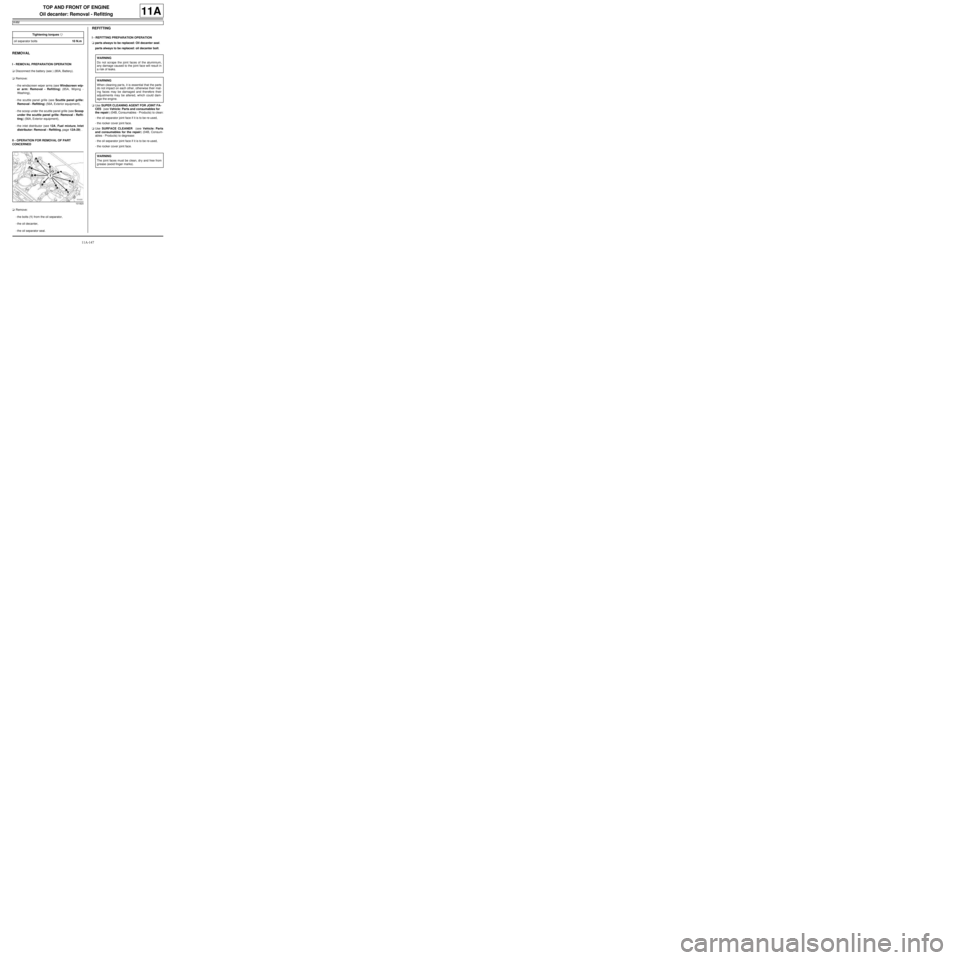
aRemove:
-the bolts (1) from the oil separator,
-the oil decanter,
-the oil separator seal.
REFITTING
I - REFITTING PREPARATION OPERATION
aparts always to be replaced: Oil decanter seal.
parts always to be replaced: oil decanter bolt.
aUse SUPER CLEANING AGENT FOR JOINT FA-
CES (see Vehicle: Parts and consumables for
the repair) (04B, Consumables - Products) to clean:
-the oil separator joint face if it is to be re-used,
-the rocker cover joint face.
aUse SURFACE CLEANER (see Vehicle: Parts
and consumables for the repair) (04B, Consum-
ables - Products) to degrease:
-the oil separator joint face if it is to be re-used,
-the rocker cover joint face. Tightening torquesm
oil separator bolts10 N.m
101820
WARNING
Do not scrape the joint faces of the aluminium,
any damage caused to the joint face will result in
a risk of leaks.
WARNING
When cleaning par ts, it is essential that the parts
do not impact on each other, otherwise their mat-
ing faces may be damaged and therefore their
adjustments may be altered, which could dam-
age the engine.
WARNING
The joint faces must be clean, dr y and free from
grease (avoid finger marks).
Page 265 of 652

11A-148
TOP AND FRONT OF ENGINE
Oil decanter: Removal - Refitting
K4M
11A
II - REFITTING OPERATION FOR PART
CONCERNED
aRefit:
-a new seal on the oil separator,
-the oil decanter.
aTighten to torque and in order the oil separator
bolts (10 N.m).
III - FINAL OPERATION
aRefit:
-the inlet distributor (see 12A, Fuel mixture, Inlet
distributor: Removal - Refitting, page 12A-29) ,
-the scoop under the scuttle panel grille (see Scoop
under the scuttle panel grille: Removal - Refit-
ting) (56A, Exterior equipment),
-the scuttle panel grille (see Scuttle panel grille:
Removal - Refitting) (56A, Exterior equipment),
-the windscreen wiper arms (see Windscreen wip-
er arm: Removal - Refitting) (85A, Wiping -
Washing).
aConnect the battery (see ) (80A, Battery).
101820
Page 285 of 652
12A-20
FUEL MIXTURE
Throttle valve: Removal - Refitting
D4F, and 772
12A
REMOVAL
I - REMOVAL PREPARATION OPERATION
aDisconnect the battery (see Battery: Removal - Re-
fitting) (80A, Battery).
aRemove the air filter unit (see 12A, Fuel mixture,
Air filter unit: Removal - Refitting, page 12A-13) .
II - OPERATION FOR REMOVAL OF PART
CONCERNED
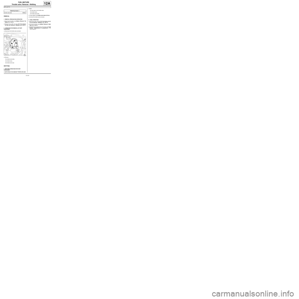
aDisconnect the throttle valve connector.
aRemove:
-the throttle valve bolts,
-the throttle valve,
-the throttle valve seal.
REFITTING
I - REFITTING OPERATION FOR PART
CONCERNED
aparts always to be replaced: Throttle valve seal.aRefit:
-the new seal on the throttle valve,
-the throttle valve,
-the throttle valve bolts.
aTorque tighten the throttle valve bolts (10 N.m).
aConnect the throttle valve connector.
II - FINAL OPERATION
aRefit the air filter unit (see 12A, Fuel mixture, Air fil-
ter unit: Removal - Refitting, page 12A-13) .
aConnect the battery (see Battery: Removal - Refit-
ting) (80A, Battery).
aReinitialise the programming of the stops (see Fault
finding - Replacement of components) (17B,
Petrol injection). Tightening torquesm
throttle valve bolts10 N.m
108810
Page 286 of 652
12A-21
FUEL MIXTURE
Throttle valve: Removal - Refitting
D4F, and 780 or 782
12A
REMOVAL
I - REMOVAL PREPARATION OPERATION
aDisconnect the battery (see ) (80A, Battery).
a
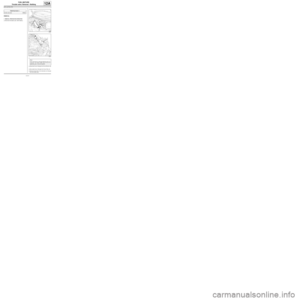
aDisconnect the air inlet pipe from the air filter box (3)
.
aMove aside the air inlet pipe from the air filter unit.
aRemove the bolt (4) of the intercooler air inlet pipe
from the throttle valve. Tightening torquesm
throttle valve bolts10 N.m
122833
122673
Note:
If the intercooler air inlet pipe tightening clip (1) is
removed, the flexible rubber pipe (2) and the
tightening clip (1) must be replaced.
Page 288 of 652

12A-23
FUEL MIXTURE
Throttle valve: Removal - Refitting
D4F, and 780 or 782
12A
-the throttle valve,
-the throttle valve seal.
REFITTING
I - REFITTING PREPARATION OPERATION
aparts always to be replaced: Throttle valve seal.
aUse SURFACE CLEANER (see Vehicle: Parts
and consumables for the repair) (04B, Consuma-
bles - Products) to clean the bearing faces:
-on the inlet distributor,
-on the throttle valve if it is to be reused.
II - REFITTING OPERATION FOR PART
CONCERNED
aRefit:
-a new seal on the throttle valve,
-the throttle valve,
-the throttle valve bolts.
aTorque tighten the throttle valve bolts (10 N.m).
aConnect the throttle valve connector.
aClip the wiring onto the throttle valve.
III - FINAL OPERATION
aRefit:
-the intercooler air outlet pipe on the throttle valve,
-the intercooler air outlet pipe bolts.
aTighten the intercooler air outlet pipe bolts.
aConnect the vacuum pipe onto the turbocharger dis-
charge solenoid valve.aPush the intercooler air inlet pipe clip in the direction
of the arrow (11) .
aFit the intercooler air inlet pipe.
aConnect the intercooler air inlet pipe on the turbo-
charger.
aRefit the intercooler air inlet pipe bolt on the throttle
valve.
aFit the air filter box air inlet pipe.
aConnect:
-the air filter unit air inlet pipe,
-the battery (see ) (80A, Battery).
aProgram the throttle valve (see Fault finding - Re-
placement of components) (17B, Petrol injection).
122666
Page 301 of 652
12A-36
FUEL MIXTURE
Inlet distributor: Removal - Refitting
D4F, and 772
12A
III - FINAL OPERATION
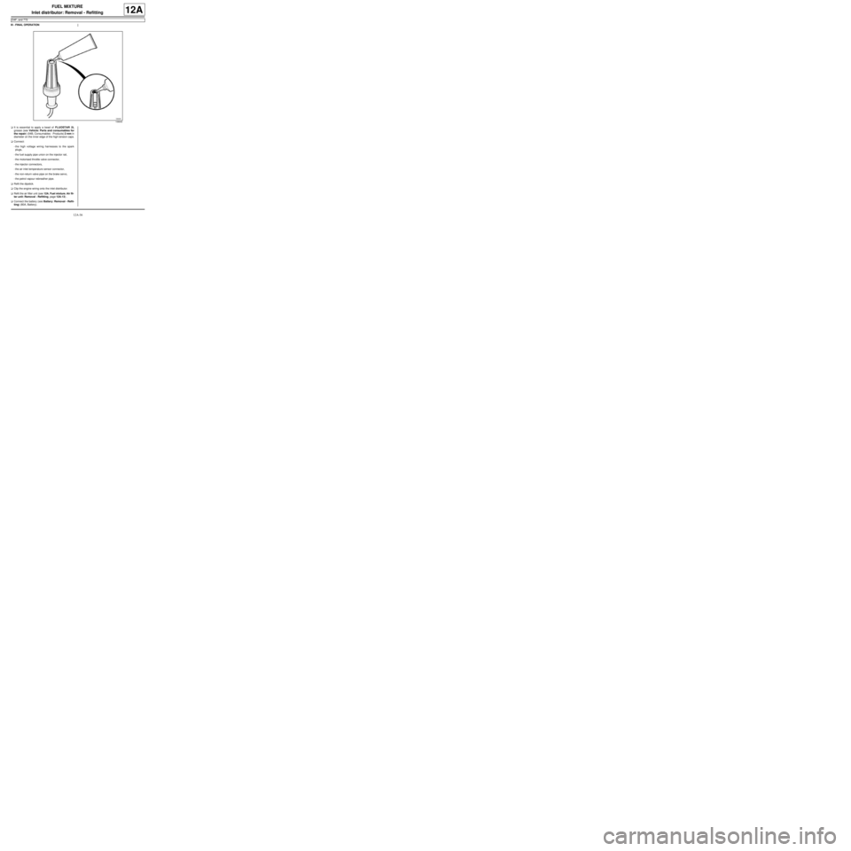
aIt is essential to apply a bead of FLUOSTAR 2L
grease (see Vehicle: Parts and consumables for
the repair) (04B, Consumables - Products) 2 mm in
diameter on the inner edge of the high tension caps.
aConnect:
-the high voltage wiring harnesses to the spark
plugs,
-the fuel supply pipe union on the injector rail,
-the motorised throttle valve connector,
-the injector connectors,
-the air inlet temperature sensor connector,
-the non-return valve pipe on the brake servo,
-the petrol vapour rebreather pipe.
aRefit the dipstick.
aClip the engine wiring onto the inlet distributor.
aRefit the air filter unit (see 12A, Fuel mixture, Air fil-
ter unit: Removal - Refitting, page 12A-13) .
aConnect the battery (see Battery: Removal - Refit-
ting) (80A, Battery).
106640
Page 305 of 652
12A-40
FUEL MIXTURE
Inlet distributor: Removal - Refitting
K4M
12A
REMOVAL
I - REMOVAL PREPARATION OPERATION
aDisconnect the battery (see Battery: Removal - Re-
fitting) (80A, Battery).
aRemove:
-the windscreen wiper arms (see Windscreen wip-
er arm: Removal - Refitting) (85A, Wiping -
Washing),-the scuttle panel grille (see Scuttle panel grille:
Removal - Refitting) (56A, Exterior equipment),
-the scoop under the scuttle panel grille (see Scoop
under the scuttle panel grille: Removal - Refit-
ting) (56A, Exterior equipment),
-the dipstick.
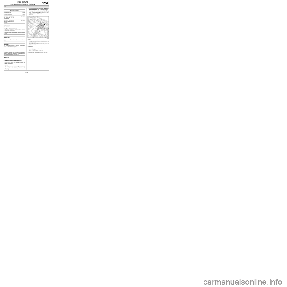
aUndo:
-the clip (1) of the air filter unit air outlet pipe on the
air filter unit side,
-the clip (2) of the air filter unit air outlet pipe on the
throttle valve side.
aDisconnect:
-the oil vapour rebreathing pipe (3) from the air filter
unit air outlet pipe,
-the air outlet pipe of the air filter unit.
aRemove the air outlet pipe from the air filter box. Tightening torquesm
throttle valve bolts10 N.m
inlet distributor bolts12 N.m
clip of the air filter unit
air outlet pipe on the
throttle valve3.5 N.m
clip of the air filter unit
air outlet pipe on the air
filter unit3.5 N.m
IMPORTANT
During this oper ation, be sure to:
-refrain from smoking or bringing red hot objects
close to the working area,
-be careful of fuel splashes when disconnecting the
union.
IMPORTANT
Wear leaktight gloves (Nitrile type) for this opera-
tion.
WARNING
To avoid any corrosion or damage, protect the
areas on which fuel is likely to run.
WARNING
To prevent impurities from entering the circuit, plugs
must be fitted to the openings of all the fuel circuit
components exposed to the open air.
132382
Page 309 of 652

12A-44
FUEL MIXTURE
Inlet distributor: Removal - Refitting
K4M
12A
aTorque tighten:
-the clip of the air filter unit air outlet pipe on the
throttle valve (3.5 N.m),
-the clip of the air filter unit air outlet pipe on the
air filter unit (3.5 N.m).
aRefit:
-the dipstick,
-the scoop under the scuttle panel grille (see Scoop
under the scuttle panel grille: Removal - Refit-
ting) (56A, Exterior equipment),
-the scuttle panel grille (see Scuttle panel grille:
Removal - Refitting) (56A, Exterior equipment),
-the windscreen wiper arms (see Windscreen wip-
er arm: Removal - Refitting) (85A, Wiping -
Washing).
aConnect the battery (see Battery: Removal - Refit-
ting) (80A, Battery).