camshaft RENAULT TWINGO RS 2009 2.G Engine And Peripherals Workshop Manual
[x] Cancel search | Manufacturer: RENAULT, Model Year: 2009, Model line: TWINGO RS, Model: RENAULT TWINGO RS 2009 2.GPages: 652
Page 3 of 652
TWINGO - Chapitre 1
Contents
Pages
TWINGO - Chapitre 1ContentsPages
10AENGINE AND CYLINDER BLOCK
ASSEMBLY
Crankshaft seal on timing
end: Removal - Refitting 10A-1
Crankshaft seal, gearbox
end: Removal - Refitting 10A-3
Lower cover: Removal -
Refitting 10A-6
Engine oil: Draining -
Refilling 10A-22
Oil filter: Removal - Refitting 10A-29
Oil-coolant heat exchanger:
Removal - Refitting 10A-33
Conrod bearing shell:
Removal - Refitting 10A-37
Oil pressure sensor:
Removal - Refitting 10A-45
Oil pump: Removal -
Refitting 10A-50
Oil pressure: Check 10A-59
Multifunction suppor t:
Removal - Refitting 10A-63
Engine - gearbox assembly:
Removal - Refitting 10A-74
Valves: Adjustment 10A-105
Flywheel: Removal - Refitting 10A-10711A TOP AND FRONT OF ENGINE
Pressure at end of
compression: Check 11A-1
Accessories belt: Removal -
Refitting 11A-3
Crankshaft accessories
pulley: Removal - Refitting 11A-20
Timing belt: Removal -
Refitting 11A-27
Rocker cover: Removal -
Refitting 11A-66
Camshaft: Removal -
Refitting 11A-82
Cylinder head: Removal -
Refitting 11A-114
Camshaft dephaser :
Removal - Refitting 11A-135
Camshaft seal, timing end:
Removal - Refitting 11A-138
Oil decanter: Removal -
Refitting 11A-147
12A FUEL MIXTURE
Air inlet: Description 12A-1
Air filter: Removal - Refitting 12A-6
Air filter unit: Removal -
Refitting 12A-13
Page 4 of 652
Contents
Air resonator : Removal -
Refitting 12A-19
Throttle valve: Removal -
Refitting 12A-20
Throttle valve: Cleaning 12A-26
Air flowmeter: Removal -
Refitting 12A-28
Inlet distributor: Removal -
Refitting 12A-29
Injector holder shim:
Removal - Refitting 12A-45
Exhaust manifold: Removal -
Refitting 12A-48
12B TURBOCHARGING
Turbocharging: Precautions
for the repair 12B-1
Turbocharger: Removal -
Refitting 12B-4
Turbocharger oil pipe:
Removal - Refitting 12B-12
Intercooler : Removal -
Refitting 12B-18
13A FUEL SUPPLY
Diesel supply circuit:
Operating diagram 13A-1
Manual pr iming pump:
Removal - Refitting 13A-2
Fuel filter : Removal -
Refitting 13A-4
Electric diesel fuel heater:
Removal - Refitting 13A-7
Fuel circuit: Operating
diagram 13A-8 12A FUEL MIXTUREFuel pressure: Check 13A-9
Fuel flow: Check 13A-14
13B DIESEL INJECTION
Diesel injection: Precautions
for the repair 13B-1
Diesel injection: List and
location of components 13B-8
Diesel injection computer:
Removal - Refitting 13B-13
Camshaft position sensor:
Removal - Refitting 13B-14
Crankshaft position sensor:
Removal - Refitting 13B-15
High pressure pump:
Removal - Refitting 13B-16
Flow actuator: Removal -
Refitting 13B-26
Venturi: Removal - Refitting 13B-31
High pressure pipe: Check 13B-34
High pressure pipe between
pump and rail: Removal -
Refitting 13B-35
High pressure pipe between
rail and injector: Removal -
Refitting 13B-39
Injector rail: Removal -
Refitting 13B-43
Rail pressure sensor:
Removal - Refitting 13B-48
Fuel temperature sensor:
Removal - Refitting 13B-49
Injector leak flow: Check 13B-51
Accelerometer : Removal -
Refitting 13B-53 13A FUEL SUPPLY
Page 7 of 652
10A-1
ENGINE AND CYLINDER BLOCK ASSEMBLY
Crankshaft seal on timing end: Removal - Refitting
K4M
10A
REMOVAL
I - REMOVAL PREPARATION OPERATION
aPosition the vehicle on a two-post lift (see Vehicle:
Towing and lifting) (02A, Lifting equipment).
aDisconnect the battery (see Battery: Removal - Re-
fitting) (80A, Battery).
aRemove:
-the engine undertray,
-the front right-hand wheel (see Wheel: Removal -
Refitting) (35A, Wheels and tyres),
-the front right-hand wheel arch liner (see Front
wheel arch liner: Removal - Refitting) (55A, Ex-
terior protection),
-the front bumper (see Front bumper: Removal -
Refitting) (55A, Exterior protection),
-the headlights (see Halogen headlight: Removal
- Refitting) (80B, Headlights),
-the bonnet catch (see Bonnet lock: Removal -
Refitting) (52A, Non-side opening element mecha-
nisms),
-the front upper cross member (see Front upper
cross member: Removal - Refitting) (42A, Upper
front structure),
-the accessories belt (see 11A, Top and front of
engine, Accessories belt: Removal - Refitting,
page 11A-3) ,
-the air filter unit (see 12A, Fuel mixture, Air filter
unit: Removal - Refitting, page 12A-13) ,
-the throttle valve (see 12A, Fuel mixture, Throttle
valve: Removal - Refitting, page 12A-20) ,
-the windscreen wiper arms (see Windscreen wip-
er arm: Removal - Refitting) (85A, Wiping -
Washing),
-the scuttle panel grille (see Scuttle panel grille:
Removal - Refitting) (56A, Exterior equipment),
-the scoop under the scuttle panel grille (see Scoop
under the scuttle panel grille: Removal - Refit-
ting) (56A, Exterior equipment),-the right-hand suspended engine mounting (see
19D, Engine mounting, Right-hand suspended
engine mounting: Removal - Refitting, page
19D-13) ,
-the crankshaft accessories pulley (see 11A, Top
and front of engine, Crankshaft accessories
pulley: Removal - Refitting, page 11A-20) ,
-the timing belt (see 11A, Top and front of engine,
Timing belt: Removal - Refitting, page 11A-27) ,
-the camshaft dephaser (see 11A, Top and front of
engine, Camshaft dephaser: Removal - Refit-
ting, page 11A-135) .
II - REMOVAL OPERATION
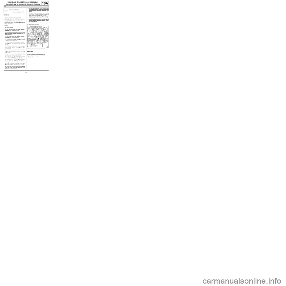
aRemove the crankshaft timing end seal (1) .
REFITTING
I - REFITTING PREPARATION OPERATION
aparts always to be replaced: Crankshaft seal on
timing end. Special tooling required
Mot. 1385Tool for fitting the crankshaft
seal, timing end (35 x 47 x 7).
130542
Page 8 of 652
10A-2
ENGINE AND CYLINDER BLOCK ASSEMBLY
Crankshaft seal on timing end: Removal - Refitting
K4M
10A
aUse SURFACE CLEANER (see Vehicle: Parts
and consumables for the repair) (04B, Consuma-
bles - Products) to clean and degrease:
-the mating face of the crankshaft seal at the timing
end,
-the crankshaft seal housing at the timing end of the
cylinder block.
II - REFITTING OPERATION
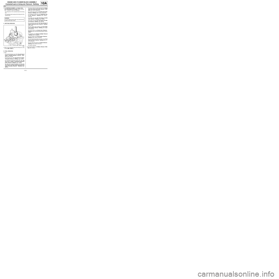
aRefit a new crankshaft seal at the timing end, using
the tool (Mot. 1385) (2) .
III - FINAL OPERATION
aRefit:
-the camshaft dephaser (see 11A, Top and front of
engine, Camshaft dephaser: Removal - Refit-
ting, page 11A-135) ,
-the timing belt (see 11A, Top and front of engine,
Timing belt: Removal - Refitting, page 11A-27) ,
-the crankshaft accessories pulley (see 11A, Top
and front of engine, Crankshaft accessories
pulley: Removal - Refitting, page 11A-20) ,
-the right-hand suspended engine mounting (see
19D, Engine mounting, Right-hand suspended
engine mounting: Removal - Refitting, page
19D-13) ,-the scoop under the scuttle panel grille (see Scoop
under the scuttle panel grille: Removal - Refit-
ting) (56A, Exterior equipment),
-the scuttle panel grille (see Scuttle panel grille:
Removal - Refitting) (56A, Exterior equipment),
-the windscreen wiper arms (see Windscreen wip-
er arm: Removal - Refitting) (85A, Wiping -
Washing),
-the throttle valve (see 12A, Fuel mixture, Throttle
valve: Removal - Refitting, page 12A-20) ,
-the air filter unit (see 12A, Fuel mixture, Air filter
unit: Removal - Refitting, page 12A-13) ,
-the accessories belt (see 11A, Top and front of
engine, Accessories belt: Removal - Refitting,
page 11A-3) ,
-the front upper cross member (see Front upper
cross member: Removal - Refitting) (42A, Upper
front structure),
-the bonnet catch (see Bonnet lock: Removal -
Refitting) (52A, Non-side opening element mecha-
nisms),
-the headlights (see Halogen headlight: Removal
- Refitting) (80B, Headlights),
-the front bumper (see Front bumper: Removal -
Refitting) (55A, Exterior protection),
-the front right-hand wheel arch liner (see Front
wheel arch liner: Removal - Refitting) (55A, Ex-
terior protection),
-the front right-hand wheel (see Wheel: Removal -
Refitting) (35A, Wheels and tyres),
-the engine undertray.
aConnect the battery (see Battery: Removal - Refit-
ting) (80A, Battery). WARNING
The joint faces must be clean, dr y and free from
grease (avoid finger marks).
14523
Page 145 of 652
11A-28
TOP AND FRONT OF ENGINE
Timing belt: Removal - Refitting
D7F, and 800
11A
aRemove the cap (3) from the upper timing cover.
aTurn the engine clockwise (timing end) until the
mark on the camshaft sprocket is aligned with the
mark on the upper timing cover.
aInsert the TDC setting pin (Mot. 1054) (4)
aRemove the ignition interference suppressor.
aDisconnect the fuel supply pipe.
aRemove the following covers:
-upper timing,
-middle timing,-lower timing.
II - REMOVAL OF PART CONCERNED
aMake a marking on the rocker cover (5) in line with
the camshaft sprocket mark
aUndo the tensioning roller nut (6) .
aRemove the timing belt.
REFITTING
I - REFITTING OPERATION FOR PART
CONCERNED
aLine up the marks on the timing belt with those on
the camshaft sprocket and crankshaft sprocket.
aRefit:
-the new timing belt,
-the new tensioning roller.
aTighten the tensioning roller.
aRemove the TDC setting rod (Mot. 1054).
107259
99795
1041
Page 151 of 652
11A-34
TOP AND FRONT OF ENGINE
Timing belt: Removal - Refitting
D4F
11A
aMake sure that the mark on the camshaft sprocket
and the mark on the crankshaft sprocket are aligned
with their fixed markings.
2 - Removing the timing belt
aRemove:
-the nut (4) from the tensioning roller,
-the tensioning roller,
-the timing belt (5) .
REFITTING
I - REFITTING PREPARATION OPERATION
aparts always to be replaced: Timing belt,
parts always to be replaced: Timing belt tension-
ing roller,
parts always to be replaced: Crankshaft acces-
sories pulley bolts.
II - REFITTING OPERATION FOR PART
CONCERNED
aRefit the new tensioning roller, making sure:
-that the cylinder head ribbing is between the two
tensioning roller lugs,
-that the tensioning roller pin is properly positioned,
-that the tensioning roller is positioned as in the dia-
gram.
aDo not remove the pin from the new tensioning roller
before refitting the timing belt.
aScrew on the tensioning roller nut without tightening
it.
109738
109738
109761
Page 152 of 652
11A-35
TOP AND FRONT OF ENGINE
Timing belt: Removal - Refitting
D4F
11A
aRefit the new timing belt:
-by lining up the crankshaft sprocket mark with the
mark on the inside of the timing belt,
-by lining up the camshaft sprocket mark with the
mark on the outside of the timing belt.
Procedure for tensioning timing belt
aRemove:
-the TDC setting pin,
-the tension wheel pin.aTurn the tensioning roller eccentric anti-clockwise,
using a 6 mm Allen key, to bring the adjustable in-
dex level with the fixed index.
aTorque tighten the tensioning roller nut (24 N.m).
aRotate the crankshaft through six revolutions in a
clockwise direction (timing end).
aSet the timing using the TDC setting pin (Mot. 1054).
109762109763
Page 153 of 652
11A-36
TOP AND FRONT OF ENGINE
Timing belt: Removal - Refitting
D4F
11A
aMake sure that the mark on the camshaft sprocket
and the mark on the crankshaft sprocket are aligned
with their fixed markings.
aRemove the TDC setting rod (Mot. 1054).aLoosen the tensioning roller nut up to one turn,
maintaining the position of the tensioning roller ec-
centric using a 6 mm Allen key.
aTurn the tensioning roller eccentric clockwise, using
a 6 mm Allen key, to bring the adjustable index to
the centre of the two fixed indexes.
aTorque tighten the tensioning roller nut (24 N.m),
maintaining the position of the eccentric using a 6
mm Allen key.
109737
109738109764
Page 155 of 652
11A-38
TOP AND FRONT OF ENGINE
Timing belt: Removal - Refitting
K9K
11A
REMOVAL
I - REMOVAL PREPARATION OPERATION
aPosition the vehicle on a two-post lift (see Vehicle:
Towing and lifting) (02A, Lifting equipment).
aDisconnect the battery (see Battery: Removal - Re-
fitting) (80A, Battery).aRemove:
-the engine cover,
-the windscreen wiper arms (see Windscreen wip-
er arm: Removal - Refitting) (85A, Wiping -
Washing),
-the scuttle panel grille (see Scuttle panel grille:
Removal - Refitting) (56A, Exterior equipment),
-the scoop under the scuttle panel grille (see Scoop
under the scuttle panel grille: Removal - Refit-
ting) (56A, Exterior equipment),
-the front wheels (see Wheel: Removal - Refitting)
(35A, Wheels and tyres),
-the front wheel arch liners (see Front wheel arch
liner: Removal - Refitting) (55A, Exterior protec-
tion),
-the front bumper (see Front bumper: Removal -
Refitting) (55A, Exterior protection),
-the halogen headlights (see Halogen headlight:
Removal - Refitting) (80B, Headlights),
-the front upper cross member (see Front upper
cross member: Removal - Refitting) (42A, Upper
front structure),
-the lower engine tie-bar (see 19D, Engine mount-
ing, Lower engine tie-bar: Removal - Refitting,
page 19D-18) ,
-the right-hand suspended engine mounting (see
19D, Engine mounting, Right-hand suspended
engine mounting: Removal - Refitting, page
19D-13) ,
-the camshaft position sensor (see 13B, Diesel in-
jection, Camshaft position sensor: Removal -
Refitting, page 13B-14) ,
-the accessories belt (see 11A, Top and front of
engine, Accessories belt: Removal - Refitting,
page 11A-3) ,
-the crankshaft accessories pulley (see 11A, Top
and front of engine, Crankshaft accessories
pulley: Removal - Refitting, page 11A-20) . Special tooling required
Mot. 1672Low er engine support.
Mot. 1489TDC locating pin.
Mot. 1430Set of 5 crankshaft and cam-
shaft pulley timing pins.
Tightening torquesm
tensioning roller bolt27 N.m
camshaft pulley wheel
bolts14 N.m
TDC setting pin plug25 N.m
cylinder head sus-
pended mounting bolts25 Nm
IMPORTANT
Wear protective gloves during the operation.
WARNING
The belt must be replaced with a new one if it has
been removed.
WARNING
When replacing the belt, always replace the tension
wheels and idler pulleys.
WARNING
Do not r un the engine without the accessories belt
to avoid damaging the crankshaft accessories pul-
ley.
Page 159 of 652
11A-42
TOP AND FRONT OF ENGINE
Timing belt: Removal - Refitting
K9K
11A
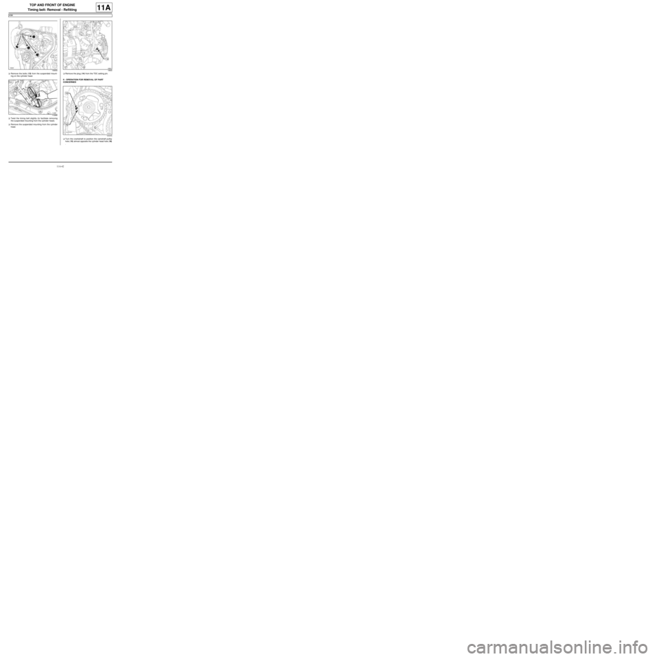
aRemove the bolts (13) from the suspended mount-
ing on the cylinder head.
aTwist the timing belt slightly (to facilitate removing
the suspended mounting from the cylinder head).
aRemove the suspended mounting from the cylinder
head.aRemove the plug (14) from the TDC setting pin.
II - OPERATION FOR REMOVAL OF PART
CONCERNED
aTurn the crankshaft to position the camshaft pulley
hole (15) almost opposite the cylinder head hole (16)
.
136658
11299819650
107270