ignition RENAULT TWINGO RS 2009 2.G Engine Diesel Injection Owner's Manual
[x] Cancel search | Manufacturer: RENAULT, Model Year: 2009, Model line: TWINGO RS, Model: RENAULT TWINGO RS 2009 2.GPages: 269
Page 83 of 269
13B-83
AFTER REPAIRDeal with any faults displayed by the diagnostic tool.
Clear the computer fault memory.
Carry out a road test followed by another check with the diagnostic tool.
V6 MR-413-X44-13B000$110.mif
DIESEL INJECTION
Fault finding – Interpretation of faults13B
DCM 1.2 Injection
Program No.: 4D
Vdiag No.: 48, 4C, 50,
54, 58, 5C
DF052
PRESENT
OR
STOREDINJECTORS CONTROL CIRCUIT
CC.1: short circuit to +12 volts.
CC.0: short circuit to earth
NOTESPriorities when dealing with a number of faults:
–DF026 Cylinder 1 injector control circuit,
–DF027 Cylinder 2 injector control circuit,
–DF028 Cylinder 3 injector control circuit,
–DF029 Cylinder 4 injector control circuit,
the fault finding procedure remains the same, but the combination of faults makes it
possible to identify the defective injector(s).
Special notes:
When the fault occurs: there is engine noise, the engine speed is unstable, the engine
performance is reduced, and the level 2 warning light comes on with the message
Faulty injection displayed on the instrument panel.
See the Technical Note Wiring Diagrams for the vehicle.
Switch off the ignition, check the condition and connection of the injector connectors, component codes 193,
194, 195, and 196.
If the connector(s) are faulty and there is a repair procedure (see Technical Note 6015A, Repairing electrical
wiring, Wiring: Precautions for repair) repair the connector(s), otherwise replace the wiring.
Switch off the ignition, disconnect the injectors (or the injector identified by faults DF026 Cylinder 1 injector
control circuit, DF027 Cylinder 2 injector control circuit, DF028 Cylinder 3 injector control circuit,
DF029 Cylinder 4 injector control circuit) and switch on the ignition again.
Using the diagnostic tool, check for changes to fault DF052.
Is DF052 present or stored?
DCM1.2_V48_DF052/DCM1.2_V4C_DF052/DCM1.2_V50_DF052/DCM1.2_V54_DF052/DCM1.2_V58_DF052/DCM1.2_V5C_DF052
Page 84 of 269
13B-84
AFTER REPAIRDeal with any faults displayed by the diagnostic tool.
Clear the computer fault memory.
Carry out a road test followed by another check with the diagnostic tool.
V6 MR-413-X44-13B000$110.mif
DIESEL INJECTION
Fault finding – Interpretation of faults13B
DCM 1.2 Injection
Program No.: 4D
Vdiag No.: 48, 4C, 50,
54, 58, 5C
DF052
CONTINUED
DF052
PRESENTThe injectors are not defective.
Check the condition and connection of the injection computer (brown 48-track)
connector B.
If the connector is faulty and there is a repair procedure (see Technical Note 6015A,
Repairing electrical wiring, Wiring: Precautions for repair), repair the connector(s),
otherwise replace the wiring.
Check the insulation, the continuity and the absence of interference resistance on
the following connections:
–3L between components 193 and 120,
–3KW between components 193 and 120,
–3LA between components 194 and 120,
–3KX between components 194 and 120,
–3LB between components 195 and 120,
–3KY between components 195 and 120,
–3LC between components 196 and 120,
–3KZ between components 196 and 120.
If the connection or connections are faulty and there is a repair procedure
(see Technical Note 6015A, Electrical wiring repair, Wiring: Precautions for repair),
repair the wiring, otherwise replace the wiring.
If the fault is still present, contact the Techline.
DF052
STOREDInjector(s) defective.
Replace the injector identified by faults DF026 Cylinder 1 injector control circuit to
DF029 Cylinder 4 injector control circuit if any are present.
If none of the faults identifying the defective injector circuit are present:
–switch off the ignition,
–reconnect one of the four injectors,
–switch on the ignition again.
If the fault recurs as present, replace the reconnected injector, component code 193,
194, 195, or 196 (see MR 364 (Mégane II), MR 370 (Scénic II), MR 385 (Modus), MR
392 (Clio III), MR 411 (New Twingo), MR 417 (Kangoo 2), Mechanical, 13B,
Diesel injection, Diesel injector: Removal - Refitting).
Follow the same procedure for the other injectors.
Page 88 of 269
13B-88
AFTER REPAIRDeal with any faults displayed by the diagnostic tool.
Clear the computer fault memory.
Carry out a road test followed by another check with the diagnostic tool.
V6 MR-413-X44-13B000$110.mif
DIESEL INJECTION
Fault finding – Interpretation of faults13B
DCM 1.2 Injection
Program No.: 4D
Vdiag No.: 48, 4C, 50,
54, 58, 5C
DF057
PRESENT
OR
STOREDWATER IN DIESEL FUEL DETECTOR CIRCUIT
CO.1: Open circuit or short circuit to + 12 V
CC.0: Short circuit to earth
1.DEF: above maximum threshold
NOTESSpecial notes:
–If water is detected downstream of the diesel filter, the high pressure pump
and the injectors may be damaged.
Use bornier Elé. 1681 for all operations on the connector of the engine management
computer.
See the Technical Note Wiring Diagrams for the vehicle.
Check the connections of the water in diesel fuel sensor, component code 414.
Check the connections of the engine management computer, component code 120.
If the connector(s) are faulty and there is a repair procedure (see Technical Note 6015A, Repairing electrical
wiring, Wiring: Precautions for repair) repair the connector(s), otherwise replace the wiring.
With the ignition on, check for +12 V on connections 3FB1 and 3FB2 (for New Twingo) or AP15 (for Kangoo 2)
of component 414.
Check for earth on the following connections:
–M or 3WU (for New Twingo) of component 120.
–MH and MW (for Kangoo 2) of component 414.
Check the continuity of the following connections:
–3WT between components 414 and 120,
–M between components 414 and 120,
–3FB1 between components 414 and 1337.
(only for New Twingo):
–3WT between components 414 and 120,
–3WU between components 414 and 120,
–3FB2 between components 414 and 238.
(only for Kangoo 2):
–AP15 between components 414 and 1337,
–3WT between components 414 and 1337,
–MH and MW between earth and component 414.
If the connection or connections are faulty and there is a repair procedure (see Technical Note 6015A, Electrical
wiring repair, Wiring: Precautions for repair), repair the wiring, otherwise replace the wiring.
DCM1.2_V48_DF057/DCM1.2_V4C_DF057/DCM1.2_V50_DF057/DCM1.2_V54_DF057/DCM1.2_V58_DF057/DCM1.2_V5C_DF057
Page 99 of 269
13B-99
AFTER REPAIRDeal with any faults displayed by the diagnostic tool.
Clear the computer fault memory.
Carry out a road test followed by another check with the diagnostic tool.
V6 MR-413-X44-13B000$110.mif
DIESEL INJECTION
Fault finding – Interpretation of faults13B
DCM 1.2 Injection
Program No.: 4D
Vdiag No.: 48, 4C, 50,
54, 58, 5C
DF112
PRESENT
OR
STOREDCYLINDER REFERENCE SENSOR CIRCUIT
1.DEF: No signal
NOTESConditions for applying fault finding procedures to stored faults:
The fault is present when the starter motor is operating or the engine is running at idle
speed.
See Technical Note Wiring Diagrams of the vehicle concerned.
Check the connection and condition of the cylinder reference sensor connector, component code 746.
If the connector is faulty and there is a repair procedure (see Technical Note 6015A, Repairing electrical wiring,
Wiring: Precautions for repair), repair the connector, otherwise replace the wiring.
Check for +12 V after ignition feed on connection 3FB2 or 3FB3 of component 746.
If the connection is faulty and there is a repair procedure (see Technical Note 6015A, Electrical wiring repair,
Wiring: Precautions for repair), repair the wiring, otherwise replace the wiring.
Check the connection and condition of connector B (brown 48-track) of the injection computer, component
code 120.
Check the connection and condition of the connector of the injection locking relay, component code 238
or the UPC, component code 1337.
If the connector(s) are faulty and there is a repair procedure (see Technical Note 6015A, Repairing electrical
wiring, Wiring: Precautions for repair) repair the connector(s), otherwise replace the wiring.
Check for earth on connection 3PL of component 746.
Check the insulation, continuity and the absence of interference resistance on the following connections:
–3CQ between components 746 and 120,
–For Clio and Modus: 3FB2 between components 1337 and 746,
–For Mégane II and Scénic II: 3FB1 and 3FB2 between components 746 and 1337,
–For New Twingo: 3FB and 3FB2 between components 746 and 238,
–For Kangoo 2: 3FB3 between components 1337 and 746.
If the connection or connections are faulty and there is a repair procedure (see Technical Note 6015A, Electrical
wiring repair, Wiring: Precautions for repair), repair the wiring, otherwise replace the wiring.
Check the timing setting.
DCM1.2_V48_DF112/DCM1.2_V4C_DF112/DCM1.2_V50_DF112/DCM1.2_V54_DF112/DCM1.2_V58_DF112/DCM1.2_V5C_DF112
Page 111 of 269
13B-111
AFTER REPAIRDeal with any faults displayed by the diagnostic tool.
Clear the computer fault memory.
Carry out a road test followed by another check with the diagnostic tool.
V6 MR-413-X44-13B000$120.mif
DIESEL INJECTION
Fault finding – Interpretation of faults13B
DCM 1.2 Injection
Program No.: 4D
Vdiag No.: 48, 4C, 50,
54, 58, 5C
DF195
PRESENT OR
STOREDENGINE SPEED/CAMSHAFT SENSOR CONSISTENCY
NOTESConditions for applying the fault finding procedure to a stored fault:
The fault is present when the starter motor is operating or the engine is running at
idle speed.
See Technical Note Wiring Diagrams of the vehicle concerned
Check the connection and condition of the cylinder reference sensor connector, component code 746.
Check the connection and condition of connector B (brown 48-track) of the injection computer, component
code 120.
Check the connection and condition of the connector of the injection locking relay, component code 238 or the
UPC, component code 1337.
If the connector(s) are faulty and there is a repair procedure (see Technical Note 6015A, Repairing electrical
wiring, Wiring: Precautions for repair) repair the connector(s), otherwise replace the wiring.
Check for +12 V after ignition feed on connection 3FB2 or 3FB3 (for Kangoo 2) of component 746.
If the connection is faulty and there is a repair procedure (see Technical Note 6015A, Electrical wiring repair,
Wiring: Precautions for repair), repair the wiring, otherwise replace it.
Check for earth on connection 3PL of component 746.
Check the insulation, continuity and the absence of interference resistance on the following connections:
–3CQ between components 746 and 120,
–3PL between components 746 and 120,
–For Clio and Modus: 3FB2 between components 1337 and 746,
–For Mégane II and Scénic II: 3FB1 and 3FB2 between components 746 and 1337,
–For New Twingo: 3FB and 3FB2 between components 746 and 238,
–For Kangoo 2: 3FB3 between components 1337 and 746.
If the connection or connections are faulty and there is a repair procedure (see Technical Note 6015A, Electrical
wiring repair, Wiring: Precautions for repair), repair the wiring, otherwise replace the wiring.
Check the timing setting.
DCM1.2_V48_DF195/DCM1.2_V4C_DF195/DCM1.2_V50_DF195/DCM1.2_V54_DF195/DCM1.2_V58_DF195/DCM1.2_V5C_DF195
Page 117 of 269
13B-117
AFTER REPAIRDeal with any faults displayed by the diagnostic tool.
Clear the computer fault memory.
Carry out a road test followed by another check with the diagnostic tool.
V6 MR-413-X44-13B000$120.mif
DIESEL INJECTION
Fault finding – Interpretation of faults13B
DCM 1.2 Injection
Program No.: 4D
Vdiag No.: 50
DF489
PRESENT OR
STOREDAIR CONDITIONING COMPRESSOR CONTROLCC.1: Short circuit to + 12 volts
C0.0: Open circuit or short circuit to earth
NOTESConditions for applying the fault finding procedure to stored faults
The fault is considered present when the engine is running.
Special notes:
The heating and air conditioning system request is not longer possible.
The compressor is still active, risk of irreparable damage to the compressor (loss of
capacity). The customer is complaining that the air conditioning is operating
continuously.
See Technical Note Wiring Diagrams of the vehicle concerned
Check the connection and condition of the injection computer connector, component code 120.
Check the connection and condition of the air conditioning compressor relay connector, component code 5845.
If the connector(s) is faulty and if there is a repair procedure (see Technical Note 6015A, Repairing electrical
wiring, Wiring: Precautions for repair), repair the connector, otherwise replace the wiring.
Run command AC180 Air conditioning compressor relay control.
If the command does not work, check, with the ignition on, for +12 V on connection 3FB of component 584 and
for earth on connection 38K of component 584.
Check the insulation and continuity of the following connections:
–38K between components 584 and 120,
–3FB between components 584 and 238.
If the connection or connections are faulty and there is a repair procedure (see Technical Note 6015A, Electrical
wiring repair, Wiring: Precautions for repair), repair the wiring, otherwise replace the wiring.
If the fault is still present, run fault finding on the climate control computer (see 62B, Climate control).
If the fault is still present, check the relay and replace it if necessary.
If the fault is still present, contact the Techline.
DCM1.2_V50_DF489
Page 121 of 269
13B-121
AFTER REPAIRDeal with any faults displayed by the diagnostic tool.
Clear the computer fault memory.
Carry out a road test followed by another check with the diagnostic tool.
V6 MR-413-X44-13B000$120.mif
DIESEL INJECTION
Fault finding – Interpretation of faults13B
DCM 1.2 Injection
Program No.: 4D
Vdiag No.: 48, 4C, 50,
54, 58, 5C
DF859
PRESENT OR
STOREDINJECTOR PROGRAMMING CYCLE NOT DONE
NOTESConditions for applying fault finding procedures to stored faults:
The fault is considered present when the engine is running.
Priorities when dealing with a number of faults:
–Deal with all the other faults before fault DF859
Special notes:
This fault is activated if the injector recalibration has not been carried out since
1800 miles (3000 km).
Leave the vehicle to run at idle speed until the engine is warm.
When the engine is warm (PR064 COOLANT TEMPERATURE above 77˚C), carry out the following test drive:
–Drive at a speed of up to 30 mph (50 km/h) and change into 5th gear.
–Stay in this gear and perform 8 accelerations from 30 mph (50 Km/h) to 54 mph (90 Km/h).
–At the end of driving: without switching off the ignition, allow the vehicle to run at idle speed for at least
10 minutes.
–Switch off the ignition, and wait 30 seconds.
–switch on the ignition, check that the fault is stored and clear the fault.
DCM1.2_V48_DF859/DCM1.2_V4C_DF859/DCM1.2_V50_DF859/DCM1.2_V54_DF859/DCM1.2_V58_DF859/DCM1.2_V5C_DF859
Page 122 of 269
13B-122
AFTER REPAIRDeal with any faults displayed by the diagnostic tool.
Clear the computer fault memory.
Carry out a road test followed by another check with the diagnostic tool.
V6 MR-413-X44-13B000$120.mif
DIESEL INJECTION
Fault finding – Interpretation of faults13B
DCM 1.2 Injection
Program No.: 4D
Vdiag No.: 48, 4C, 50,
54, 58, 5C
DF886
PRESENT OR
STOREDPRESENCE OF WATER IN THE DIESEL FUEL
NOTESPriorities when dealing with a number of faults:
–DF057 Water in diesel fuel detector circuit,
Special notes:
If water is detected downstream of the diesel filter, the high pressure pump and
the injectors may be damaged.
The level 1 warning light is illuminated.
Use bornier Elé. 1681 for all operations on the engine management computer
connector.
See the Technical Note Wiring Diagrams for the vehicle.
If there is water present, bleed the diesel filter.
If there is a great amount of water, run the first part of Test 13: Diesel fuel conformity check (Is the fuel cloudy
or does it separate into 2 parts?)
Check the connections of the water in diesel fuel sensor, component code 414.
Check the connections of the engine management computer grey connector, component code 120.
If the connector(s) are faulty and there is a repair procedure (see Technical Note 6015A, Repairing electrical
wiring, Wiring: Precautions for repair), repair the connector(s), otherwise replace the wiring.
With the ignition on, check for +12 V on connections 3FB1 or 3FB2 (for New Twingo) or AP15 (for Kangoo 2) of
component 414.
Check for earth on connections M or 3WU (only for New Twingo) of component 120.
If the connection or connections are faulty and there is a repair procedure (see Technical Note 6015A, Electrical
wiring repair, Wiring: Precautions for repair), repair the wiring, otherwise replace the wiring.
DCM1.2_V48_DF886/DCM1.2_V4C_DF886/DCM1.2_V50_DF886/DCM1.2_V54_DF886/DCM1.2_V58_DF886/DCM1.2_V5C_DF886
Page 126 of 269
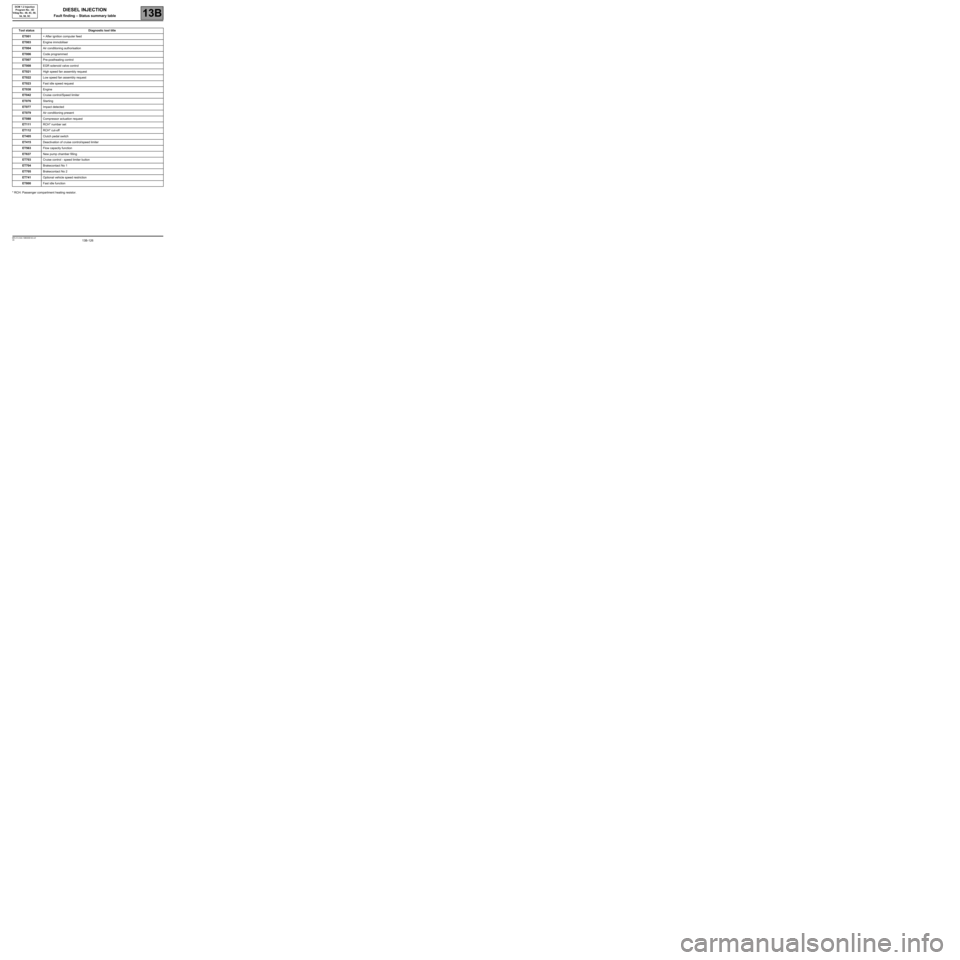
13B-126V6 MR-413-X44-13B000$140.mif
13B
DCM 1.2 Injection
Program No.: 4D
Vdiag No.: 48, 4C, 50,
54, 58, 5C
* RCH: Passenger compartment heating resistor.Tool status Diagnostic tool title
ET001+ After ignition computer feed
ET003Engine immobiliser
ET004Air conditioning authorisation
ET006Code programmed
ET007Pre-postheating control
ET008EGR solenoid valve control
ET021High speed fan assembly request
ET022Low speed fan assembly request
ET023Fast idle speed request
ET038Engine
ET042Cruise control/Speed limiter
ET076Starting
ET077Impact detected
ET079Air conditioning present
ET088Compressor actuation request
ET111RCH* number set
ET112RCH* cut-off
ET405Clutch pedal switch
ET415Deactivation of cruise control/speed limiter
ET563Flow capacity function
ET637New pump chamber filling
ET703Cruise control - speed limiter button
ET704Brakecontact No 1
ET705Brakecontact No 2
ET741Optional vehicle speed restriction
ET800Fast idle function
DIESEL INJECTION
Fault finding – Status summary table
Page 127 of 269
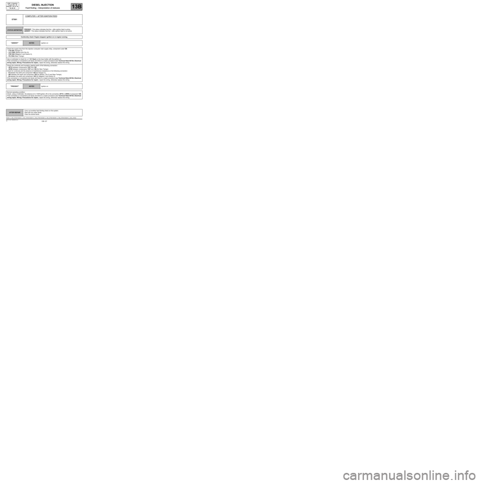
13B-127
AFTER REPAIRCarry out another fault finding check on the system.
Deal with any other faults.
Clear the stored faults.
V6 MR-413-X44-13B000$150.mif
13B
DCM 1.2 Injection
Program No.: 4D
Vdiag No.: 48, 4C, 50,
54, 58, 5C
ET001COMPUTER + AFTER IGNITION FEED
STATUS DEFINITIONPRESENT: This status indicates that the + after ignition feed is active.
ABSENT: This status indicates that the + after ignition feed is not active.
Conformity check: Engine stopped, ignition on or engine running.
"ABSENT"
NOTESIgnition on
Check the supply fuse from the injection computer main supply relay, component code 120.
–F18 (5A) (Kangoo 2),
–313 (10A) (Modus and Clio III),
–F5D (5A) (Mégane II and Scénic II),
–F9 (15A) (New Twingo)
Use a multimeter to check for a + 12 V feed on the fuse holder with the ignition on.
If the connection or connections are faulty and there is a repair procedure (see Technical Note 6015A, Electrical
wiring repair, Wiring: Precautions for repair), repair the wiring, otherwise replace the wiring.
Check the continuity and insulation against earth of the following connection:
–AP15 between components 1337 and 120
–AP29 between components 1337 and 120 (for New Twingo)
Check for continuity and the absence of interference resistance on the following connection:
–N between the earth and component 120 (for Kangoo 2),
–NH between the earth and component 120 (for Modus, Clio III and New Twingo),
–M between the earth and component 120 (for Mégane II and Scénic II).
If the connection or connections are faulty and there is a repair procedure (see Technical Note 6015A, Electrical
wiring repair, Wiring: Precautions for repair), repair the wiring, otherwise replace the wiring.
"PRESENT"
NOTESIgnition on
Normal operating condition:
Check, using a multimeter, the absence of a + 12 V ignition off on the connection AP15 or AP29 of component 120.
If the connection or connections are faulty and there is a repair procedure (see Technical Note 6015A, Electrical
wiring repair, Wiring: Precautions for repair), repair the wiring, otherwise replace the wiring.
DCM1.2_V48_ET001/DCM1.2_V4C_ET001/DCM1.2_V50_ET001/DCM1.2_V54_ET001/DCM1.2_V58_ET001/DCM1.2_V5C_ET001
DIESEL INJECTION
Fault finding – Interpretation of statuses