window RENAULT TWINGO RS 2009 2.G Mechanism And Accessories Workshop Manual
[x] Cancel search | Manufacturer: RENAULT, Model Year: 2009, Model line: TWINGO RS, Model: RENAULT TWINGO RS 2009 2.GPages: 95
Page 1 of 95
© Renault s.a.s 2007 "The repair procedures given by the manufacturer in this document are based on the
technical specifications current when it was prepared.
The procedures may be modified as a result of changes introduced by the manufacturer in
the production of the various component units and accessories from which the vehicles are
constructed".All rights reserved by Renault.
Copying or translating, in part or in full, of this document or use of the service part reference
numbering system is forbidden without the prior written authority of Renault.
JUNE 2009 EDITION ANGLAISE
X44
5Mechanisms and accessories
51ASIDE OPENING ELEMENT MECHANISMS
52ANON-SIDE OPENING ELEMENT MECHANISMS
54AWINDOWS
55AEXTERIOR PROTECTION
56AEXTERIOR EQUIPMENT
57AINTERIOR EQUIPMENT
59ASAFETY ACCESSORIES
Page 2 of 95
TWINGO - Section 5
Contents
Pages
TWINGO - Section 5 ContentsPages
51A SIDE OPENING ELEMENT MECHANISMS
Front side door lock:
Removal - Refitting 51A-1
Front side door lock barrel:
Removal - Refitting 51A-3
Exter ior door handle:
Removal - Refitting 51A-5
Front side door electric
window mechanism:
Removal - Refitting 51A-6
Front side door manual
window winder mechanism:
Removal - Refitting 51A-8
Front side door check strap:
Removal - Refitting 51A-10
52ANON-SIDE OPENING ELEMENT
MECHANISMS
Bonnet lock: Removal -
Refitting 52A-1
Bonnet release cable:
Removal - Refitting 52A-2
Tailgate lock: Removal -
Refitting 52A-3
Tailgate strut: Removal -
Refitting 52A-4
Tailgate exterior opening
control: Removal - Refitting 52A-5
Sunroof operating
mechanism: Removal -
Refitting 52A-6
Sunroof mobile panel:
Removal - Refitting 52A-9
Sunroof mobile panel guide:
Removal - Refitting 52A-12
Sunroof deflector: Removal -
Refitting 52A-14
Sunroof sun visors: Removal
- Refitting 52A-15
54A WINDOWS
Windscreen: Removal -
Refitting 54A-1
Front side door sliding
window: Removal - Refitting 54A-3
Rear quar ter panel window:
Removal - Refitting 54A-4
Rear screen: Removal -
Refitting 54A-5
Sunroof fixed window:
Removal - Refitting 54A-7 52ANON-SIDE OPENING ELEMENT
MECHANISMS
Page 4 of 95
51A-1
SIDE OPENING ELEMENT MECHANISMS
Front side door lock: Removal - Refitting
51A
REMOVAL
I - REMOVAL PREPARATION OPERATION
aRemove:
-the front side door trim (see Front side door trim:
Removal - Refitting) (MR 412, 72A, Side opening
element trim),
-the door sealing film (see Door sealing film: Re-
moval - Refitting) (MR 412, 65A, Opening ele-
ment sealing),
-the door exterior handle (see 51A, Side opening
element mechanisms, Exterior door handle:
Removal - Refitting, page 51A-5) .
aRemove the bolts (1) .
aUndo the bolts (2) .
aRemove:
-the lower guide on the sliding window,
-the front side door lock barrel (see 51A, Side ope-
ning element mechanisms, Front side door lock
barrel: Removal - Refitting, page 51A-3) .aUndo the front side door lock catch (3) (depending
on equipment level).
II - REMOVAL OPERATION FOR PART
CONCERNED
aRemove the bolts (4) . Tightening torquesm
door lock bolts8 Nm
119278
121218
119256
Page 5 of 95

51A-2
SIDE OPENING ELEMENT MECHANISMS
Front side door lock: Removal - Refitting
51A
aGently lift the door lock to extract it from the retaining
hook (5) .
aUnclip the interior locking linkage on the door lock
(depending on equipment level).
aDisconnect the door lock supply connector (depen-
ding on equipment level).
aRemove the lock from the door box section.
REFITTING
I - REFITTING OPERATION FOR PART
CONCERNED
aPosition the sealing foam on the lock (depending on
equipment level) (part no. 82 00 556 180).
aFit the lock into the door box section.
aClip the interior locking linkage onto the door lock
(depending on equipment level).
aPosition the door lock on the retaining hook (5) .
aConnect the door lock supply connector (depending
on equipment level).
aRefit the bolts (4) without tightening them.aTorque tighten the door lock bolts (8 Nm) following
the tightening order:
-bolt (5) ,
-bolt (6) ,
-bolt (7) .
aCarry out a function test.
II - FINAL OPERATION.
aFit the front side door lock catch (3) .
aRefit:
-the front side door lock barrel (see 51A, Side ope-
ning element mechanisms, Front side door lock
barrel: Removal - Refitting, page 51A-3) ,
-the lower guide on the sliding window,
-the bolts (1) .
aTighten the bolts (2) .
aRefit:
-the door exterior handle (see 51A, Side opening
element mechanisms, Exterior door handle:
Removal - Refitting, page 51A-5) ,
-the door sealing film (see Door sealing film: Re-
moval - Refitting) (MR 412, 65A, Opening ele-
ment sealing),
-the front side door trim (see Front side door trim:
Removal - Refitting) (MR412, 72A, Side opening
elements trim).
18696119256
Page 9 of 95

51A-6
SIDE OPENING ELEMENT MECHANISMS
Front side door electric window mechanism: Removal - Refitting51A
REMOVAL
I - REMOVAL PREPARATION OPERATION
aRemove:
-the front side door trim (see Front side door trim:
Removal - Refitting) (MR 412, 72A, Side opening
element trim),
-the door sealing film (see Door sealing film: Re-
moval - Refitting) (MR 412, 65A, Opening ele-
ment sealing),
-the front side sliding door window (see 54A, Win-
dows, Front side door sliding window: Removal
- Refitting, page 54A-3) or keep it in the raised po-
sition with masking tape.
II - REMOVAL OPERATION FOR PART
CONCERNED
aRemove:
-the bolts (1) ,
-the bolts (2) .
aDisconnect the window winder mechanism supply
connector.
aRemove the window lift mechanism.
REFITTING
I - REFITTING OPERATION FOR PART
CONCERNED
aRefit the window lift mechanism.
aConnect the window winder mechanism supply con-
nector.
aRefit:
-the window winder mechanism bolts without tighte-
ning them,
-the front side sliding door window (see 54A, Win-
dows, Front side door sliding window: Removal
- Refitting, page 54A-3) or keep it in the raised po-
sition with masking tape.
a
aTorque tighten the electric window winder mecha-
nism bolts ( 6.5 Nm) following the tightening order:
-bolt (3) ,
-bolt (4) ,
-bolt (5) .
aCarry out a function test. Tightening torquesm
electr ic window winder
mechanism bolts6.5 Nm
119280
119280
Note:
When refitting the window winder mechanism,
follow the tightening order of the bolts.
The tightening order ensures the window winder
mechanism is correctly aligned.
Page 10 of 95

51A-7
SIDE OPENING ELEMENT MECHANISMS
Front side door electric window mechanism: Removal - Refitting51A
II - FINAL OPERATION.
aRefit:
-the door sealing film (see Door sealing film: Re-
moval - Refitting) (MR 412, 65A, Opening ele-
ment sealing),
-the front side door trim (see Front side door trim:
Removal - Refitting) (MR 412, 72A, Side opening
element trim),
aInitialise the window winder motor (see Electric
window: Initialisation) (MR 413, 87D, Electric win-
dows - Sunroof).
Page 11 of 95
51A-8
SIDE OPENING ELEMENT MECHANISMS
Front side door manual window winder mechanism: Removal - Refitting51A
REMOVAL
I - REMOVAL PREPARATION OPERATION
aRemove:
-the front side door trim (see Front side door trim:
Removal - Refitting) (MR 412, 72A, Side opening
element trim),
-the door sealing film (see Door sealing film: Re-
moval - Refitting) (MR 412, 65A, Opening ele-
ment sealing),
-the front side sliding door window (see 54A, Win-
dows, Front side door sliding window: Removal
- Refitting, page 54A-3) or keep it in the raised po-
sition with masking tape.
II - REMOVAL OPERATION FOR PART
CONCERNED
aRemove:
-the bolts (1) ,
-the bolts (2) .
aRemove the window lift mechanism.
REFITTING
I - REFITTING OPERATION FOR PART
CONCERNED
aCheck that there is sealing foam on the manual win-
dow winder mechanism.
aRefit:
-the window winder mechanism,
-the window winder mechanism bolts without tighte-
ning them,
-the front side sliding door window (see 54A, Win-
dows, Front side door sliding window: Removal
- Refitting, page 54A-3) or keep it in the raised po-
sition with masking tape.
a
aTorque tighten the manual window winder mecha-
nism bolts ( 6.5 Nm) following the tightening order:
-bolt (3) ,
-bolt (4) ,
-bolt (5) .
aCarry out a function test. Tightening torquesm
manual window winder
mechanism bolts6.5 Nm
121455
121455
Note:
When refitting the window winder mechanism,
follow the tightening order of the bolts.
The tightening order ensures the window winder
mechanism is correctly aligned.
Page 12 of 95

51A-9
SIDE OPENING ELEMENT MECHANISMS
Front side door manual window winder mechanism: Removal - Refitting51A
II - FINAL OPERATION.
aRefit:
-the door sealing film (see Door sealing film: Re-
moval - Refitting) (MR 412, 65A, Opening ele-
ment sealing),
-the front side door trim (see Front side door trim:
Removal - Refitting) (MR412, 72A, Side opening
elements trim).
Page 20 of 95
52A-6
NON-SIDE OPENING ELEMENT MECHANISMS
Sunroof operating mechanism: Removal - Refitting
52A
REMOVAL
I - REMOVAL PREPARATION OPERATION
aPartially open the sunroof mobile panel.
aLock the airbag computer using the Diagnostic tool
(see Fault finding - Replacement of components)
(MR 413, 88C, Airbags and seat belt pretensioners).
aDisconnect the battery (see Battery: Removal - Re-
fitting) (MR 411, 80A, Battery).
aRemove:
-the sunroof console (see Sunroof switch: Remo-
val - Refitting) (MR 411, 87D, Electric window win-
ders - Sunroof),
-the sun visors (see 57A, Interior equipment, Sun
visor: Removal - Refitting, page 57A-16) ,
-the A-pillar trims (see Windscreen pillar trim: Re-
moval - Refitting) (MR 412, 71A, Body internal
trim),
-the rear bench seatback (depending on equipment
level) (see Rear bench seatback: Removal - Re-
fitting) (MR 412, 76A, Rear seat frames and run-
ners),
-the rear parcel shelf side trim panels (see Rear
parcel shelf side trim: Removal - Refitting) (MR
412, 71A, Body internal trim),-the rear panel trims (see Rear panel lining: Re-
moval - Refitting) (MR 412, 71A, Body internal
trim),
-the B-pillar upper trims (see B-pillar upper trim:
Removal - Refitting) (MR 412, 71A, Body internal
trim),
-the rear quarter panel trims (see Quarter panel
trim: Removal - Refitting) (MR 412, 71A, Body in-
ternal trim),
-the headlining (see Headlining: Removal - Refit-
ting) (MR 412, 71A, Body internal trim),
-the cross member mounting of the sunroof sun vi-
sor (see 52A, Non-side opening element mecha-
nisms, Sunroof sun visors: Removal - Refitting,
page 52A-15) ,
-the roof protection strips (see 55A, Exterior pro-
tection, Roof protection strip: Removal - Refit-
ting, page 55A-17) .
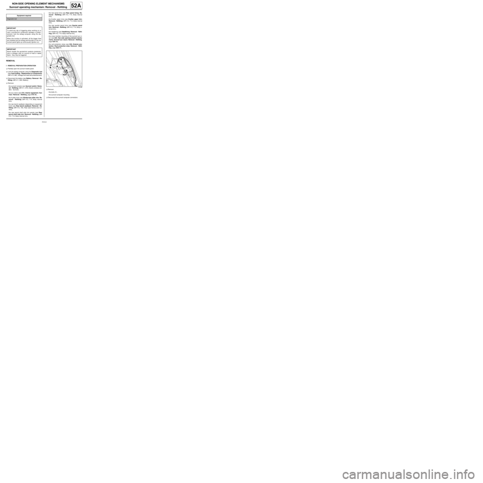
aRemove:
-the bolts (1) ,
-the sunroof computer mounting.
aDisconnect the sunroof computer connectors. Equipment required
Diagnostic tool
IMPORTANT
To avoid any risk of triggering when working on or
near a pyrotechnic component (airbags or preten-
sioners), lock the airbag computer using the dia-
gnostic tool.
When this function is activated, all the trigger lines
are inhibited and the airbag warning light on the ins-
trument panel lights up contin uously (ignition on).
IMPORTANT
Never handle the pyrotechnic systems (pretensio-
ners or airbags) near to a source of heat or naked
flame - they may be triggered.
121396
Page 21 of 95
52A-7
NON-SIDE OPENING ELEMENT MECHANISMS
Sunroof operating mechanism: Removal - Refitting
52A
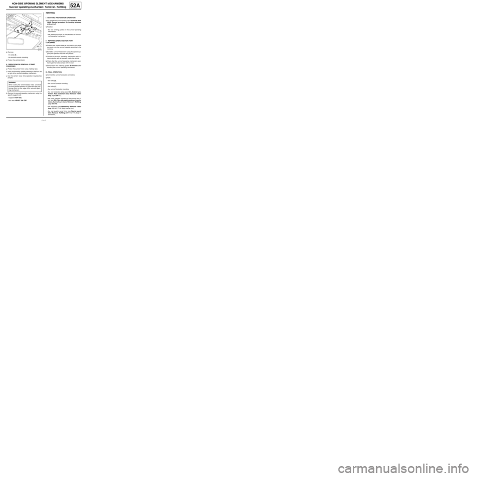
aRemove:
-the bolts (2) ,
-the sunroof console mounting.
aProtect the vehicle interior.
II - OPERATION FOR REMOVAL OF PART
CONCERNED
aProtect the sunroof frame using masking tape.
ainsert the threading needle preferably at the front left
or right of the sunroof operating mechanism.
aCut the cement bead (this operation requires two
people).
aRemove the sunroof operating mechanism using the
specific support (x2):
-Support: PARV 202,
-arch sets: APARV 200 ESP.
REFITTING
I - REFITTING PREPARATION OPERATION
aFor preparation and bonding see Technical Note
560A, General procedure for bonding windows
and sunroof.
aPosition:
-the two centring guides on the sunroof operating
mechanism,
-the positioning shims on the periphery of the sun-
roof operating mechanism.
II - REFITTING OPERATION FOR PART
CONCERNED
aPosition the cement bead at the interior roof panel
surround or on the sunroof cassette according to the
marking.
aBond the sunroof mechanism using the special sup-
port (this operation requires two people).
aCentre the sunroof operating mechanism with in-
dexing guides with an operator inside the vehicle.
aCheck that the sunroof operating mechanism posi-
tioning shims make contact with the roof.
aRemove the two indexing guides 30 minutes after
bonding the sunroof operating mechanism.
III - FINAL OPERATION.
aConnect the sunroof computer connectors.
aRefit:
-the bolts (2) ,
-the sunroof console mounting,
-the bolts (1) ,
-the sunroof computer mounting,
-the roof protection strips (see 55A, Exterior pro-
tection, Roof protection strip: Removal - Refit-
ting, page 55A-17) ,
-the cross member mounting of the sunroof sun vi-
sor (see 52A, Non-side opening element mecha-
nisms, Sunroof sun visors: Removal - Refitting,
page 52A-15) ,
-the headlining (see Headlining: Removal - Refit-
ting) (MR 412, 71A, Body internal trim),
-the rear quarter panel trims (see Quarter panel
trim: Removal - Refitting) (MR 412, 71A, Body in-
ternal trim),
121715
WARNING
When cutting the cement bead, make sure that
the wire passes between the panel and the posi-
tioning shims on the edge of the sunroof opera-
ting mechanism.