RENAULT TWINGO RS 2009 2.G Panelwork User Guide
TWINGO RS 2009 2.G
RENAULT
RENAULT
https://www.carmanualsonline.info/img/7/1724/w960_1724-0.png
RENAULT TWINGO RS 2009 2.G Panelwork User Guide
Page 160 of 209
44A-5
REAR UPPER STRUCTURE
Rear lights mounting: General description
44A
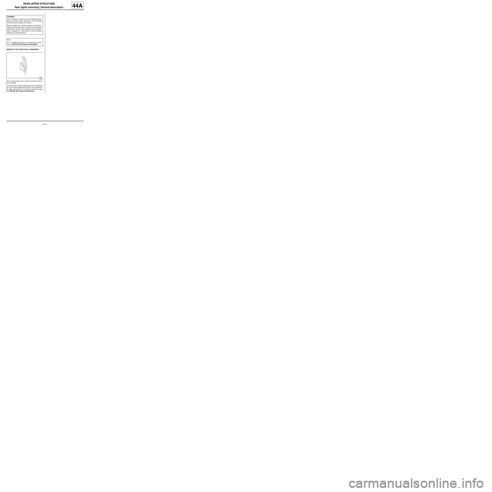
DESIGN OF THE STRUCTURAL COMPONENT
This is a basic part; its only function is that of a rear li-
ghts mounting.
If there are other issues regarding access to mating fa-
ces, the various replacement options are described in
the basic instructions for structural bodywork repair
(see MR 400, 40A, General Information). WARNING
The information contained in the following descri-
bes the general repair procedure for all vehicles
having the same design for this part.
Before reading the following general information,
make sure that there are no special notes associa-
ted with the vehicle. These special notes are speci-
fied if necessary in other par ts of the sub-section
dealing with the component.
Note:
For a detailed description of a particular connec-
tion, see MR 400, 40A, General Information.
109669
Page 161 of 209
44A-6
REAR UPPER STRUCTURE
Rear lights mounting: Description
C44
44A
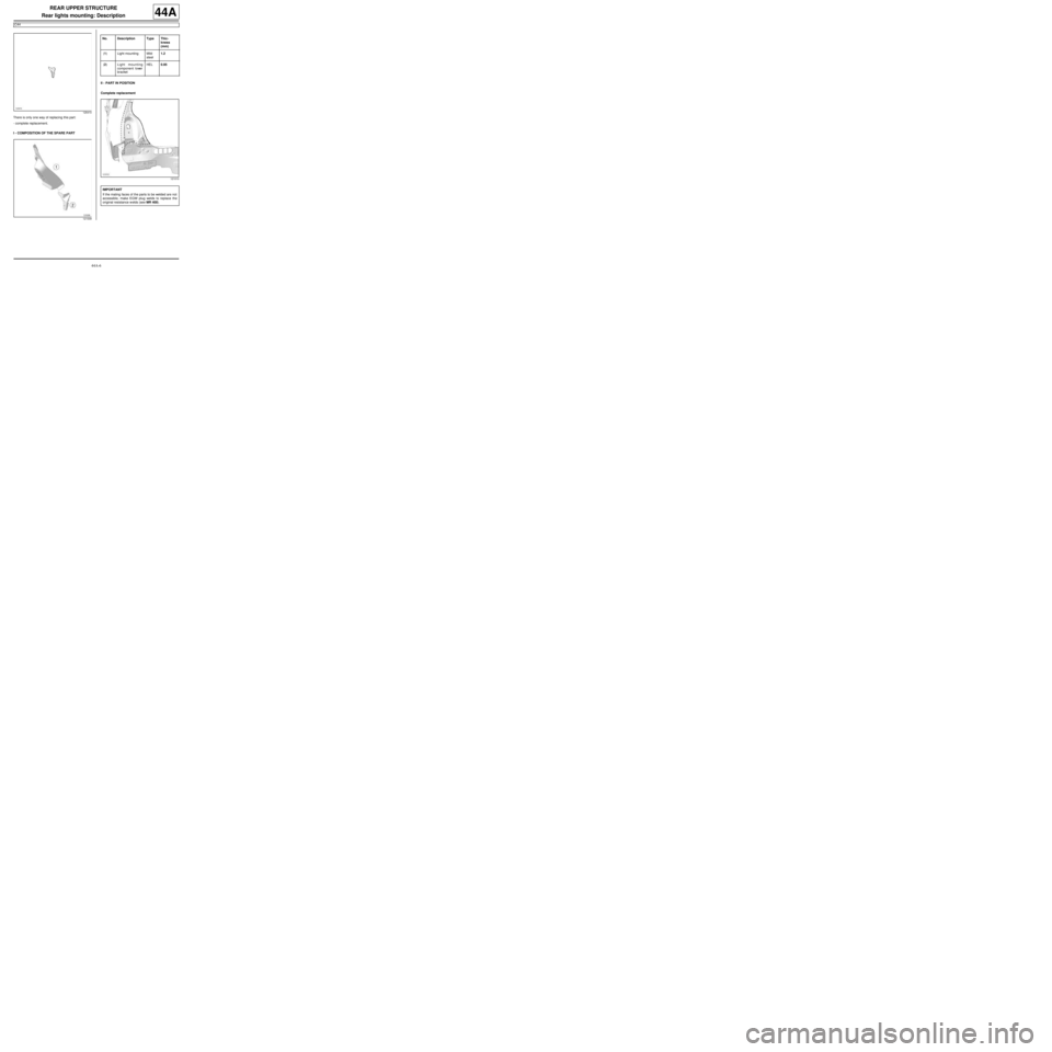
There is only one way of replacing this part:
-complete replacement.
I - COMPOSITION OF THE SPARE PARTII - PART IN POSITION
Complete replacement
125410
121009
No. Description Type Thic-
kness
(mm)
(1) Light mounting Mild
steel1.2
(2) Light mounting
component lower
bracketHEL0.95
121010
IMPORTANT
If the mating faces of the parts to be welded are not
accessible, make EGW plug welds to replace the
original resistance welds (see MR 400).
Page 162 of 209
44A-7
REAR UPPER STRUCTURE
Rear lights mounting: Description
C44
44A
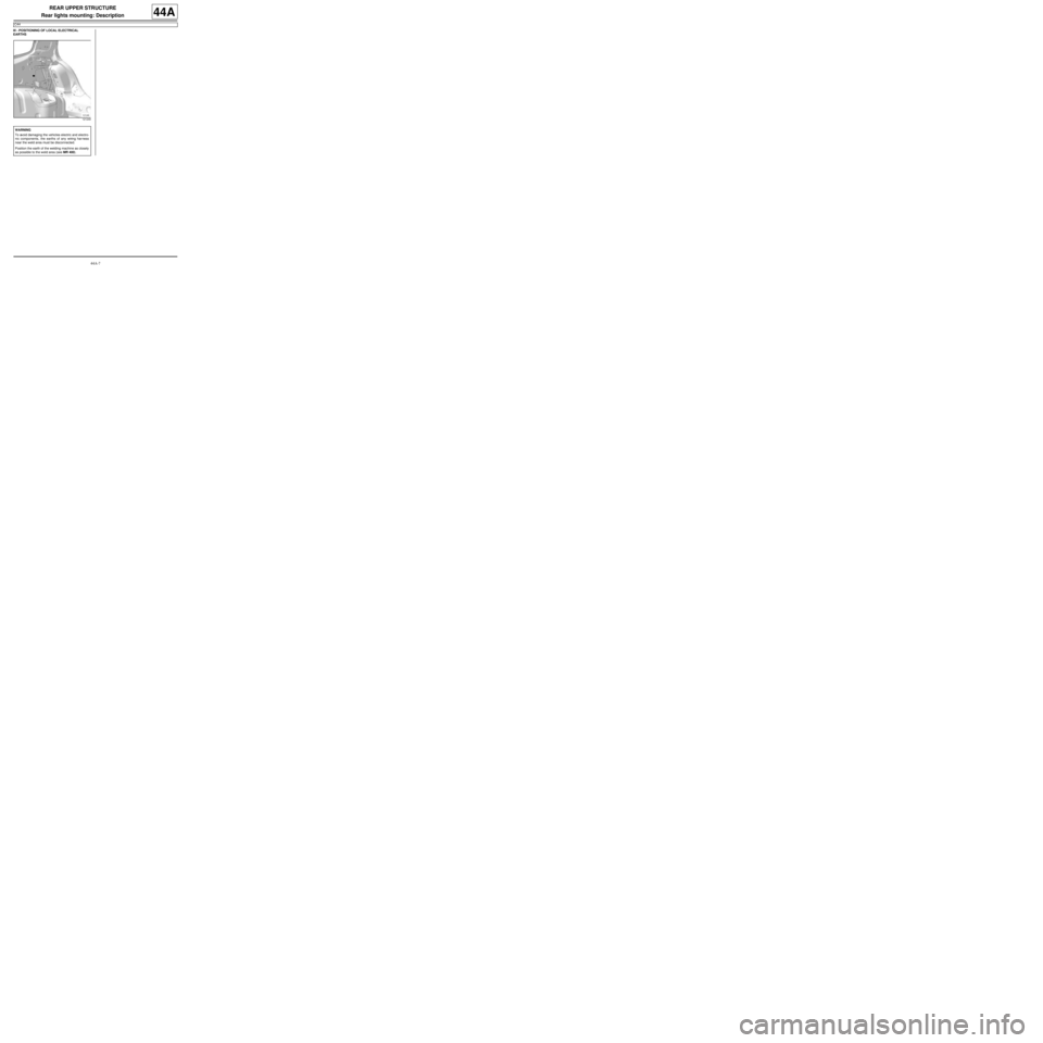
III - POSITIONING OF LOCAL ELECTRICAL
EARTHS
121249
WARNING
To avoid damaging the vehicles electric and electro-
nic components, the earths of any wiring harness
near the weld area must be disconnected.
Position the earth of the welding machine as closely
as possible to the weld area (see MR 400).
Page 200 of 209

48A-1
NON-SIDE OPENING ELEMENTS
Bonnet: Removal - Refitting
48A
I - REMOVAL BY MEANS OF THE BONNET BOLTS
1 - REMOVAL PREPARATION OPERATION
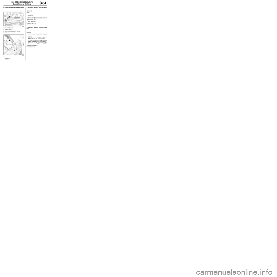
aDisconnect the pipe (1) .
aUnclip the pipe at (2) .
2 - OPERATION FOR REMOVAL OF PART
CONCERNED
aRemove:
-the bolts (3) ,
-the bonnet.II - REFITTING BY MEANS OF THE BONNET BOLTS
1 - OPERATION FOR REFITTING PART
CONCERNED
aRefit:
-the bonnet,
-the bolts (3) .
aAdjust the opening clearances and flush fitting (see
48A, Non-side opening elements, Bonnet: Ad-
justment, page 48A-4) .
2 - FINAL OPERATION
aClip on the pipe at (2) .
aConnect the pipe at (1) .
III - REMOVAL BY MEANS OF THE BONNET HINGE
BOLTS
1 - REMOVAL PREPARATION OPERATION
aRemove:
-the front wheel arch liner (see Front wheel arch
liner: Removal - Refitting) (MR 412, 55A, Exterior
protection),
-the front bumper (see Front bumper: Removal -
Refitting) (MR 412, 55A, Exterior protection),
-the halogen headlights (see Halogen headlight:
Removal - Refitting) (MR 411, 80B, Headlights),
-the front wing (see 42A, Front upper structure,
Front wing: Removal - Refitting, page 42A-3) ,
aDisconnect the pipe at (1) .
aUnclip the pipe at (2) .
112036
121519
Page 201 of 209
48A-2
NON-SIDE OPENING ELEMENTS
Bonnet: Removal - Refitting
48A
2 - OPERATION FOR REMOVAL OF PART
CONCERNED
aRemove:
-the bolts (4) ,
-the bonnet.
IV - REFITTING BY MEANS OF THE BONNET
HINGE BOLTS
1 - OPERATION FOR REFITTING PART
CONCERNED
aRefit:
-the bonnet,
-the bolts (4) .
aAdjust the opening clearances and flush fitting (see
48A, Non-side opening elements, Bonnet: Remo-
val - Refitting, page 48A-1) .
2 - FINAL OPERATION
aClip on the pipe at (2) .
aConnect the pipe at (1) .
aRefit:
-the front wing (see 42A, Front upper structure,
Front wing: Removal - Refitting, page 42A-3) ,
-the halogen headlights (see Halogen headlight:
Removal - Refitting) (MR 411, 80B, Headlights),
-the front bumper (see Front bumper: Removal -
Refitting) (MR 412, 55A, Exterior protection),-the front wheel arch liner (see Front wheel arch
liner: Removal - Refitting) (MR 412, 55A, Exterior
protection).
121519


