lights RENAULT TWINGO RS 2009 2.G Panelwork Workshop Manual
[x] Cancel search | Manufacturer: RENAULT, Model Year: 2009, Model line: TWINGO RS, Model: RENAULT TWINGO RS 2009 2.GPages: 209
Page 4 of 209
Contents
Front wing upper mounting
support: Removal - Refi tting 42A-7
Front end panel: General
descr iption 42A-8
Front end panel: Removal -
Refitting 42A-9
Headlight carrier panel:
Removal - Refitting 42A-11
Front upper cross member:
General description 42A-12
Front upper cross member:
Removal - Refitting 42A-13
Scuttle side panel: General
descr iption 42A-14
Scuttle side panel:
Description 42A-16
Upper reinforcement of
scuttle side panel: General
descr iption 42A-18
Upper reinforcement of
scuttle side panel:
Description 42A-19
Front wheel arch: General
descr iption 42A-21
Front wheel arch: Description 42A-22
Front wheel arch, front
section: General description 42A-25
Dashboard cross member:
Removal - Refitting 42A-26
Windscreen aperture lower
cross member closure panel:
Description 42A-28
43A SIDE UPPER STRUCTURE
A-pillar : General description 43A-1
A-pillar : Description 43A-2
A-pillar reinforcement:
General description 43A-5 42A FRONT UPPER STRUCTUREA-pillar reinforcement:
Description 43A-6
Windscreen pillar lining:
General description 43A-8
B-pillar reinforcement:
General description 43A-9
B-pillar reinforcement:
Description 43A-10
Body side: General
descr iption 43A-12
Body side: Description 43A-13
Upper body: General
descr iption 43A-15
Upper body: Description 43A-17
44A REAR UPPER STRUCTURE
Rear wing panel: General
descr iption 44A-1
Rear wing panel: Description 44A-2
Rear lights mounting:
General description 44A-5
Rear lights mounting:
Description 44A-6
Outer rear wheel arch:
General description 44A-8
Outer rear wheel arch:
Description 44A-10
Inner rear wheel arch:
General description 44A-13
Inner rear wheel arch:
Description 44A-14
Quar ter panel lining: General
descr iption 44A-16
Quar ter panel lining:
Description 44A-17
Rear end panel assembly:
Description 44A-22 43A SIDE UPPER STRUCTURE
Page 27 of 209
40A-22
GENERAL INFORMATION
Vehicle structure, rear section: Description
40A
(9) Rear light mounting (see 44A, Rear upper structure, Rear lights mounting:
Description, page 44A-6)
(10) Rear towing eye (see 41D, Rear lower structure, Rear towing eye: Des-
cription, page 41D-16)
(11) Quarter panel lining (see 44A, Rear upper structure, Quarter panel lining:
Description, page 44A-17)
(12) Rear end panel (see 44A, Rear upper structure, Rear end panel: Des-
cription, page 44A-25) No. Description Classification Type Thickness
(mm)
Page 109 of 209
41D-18
REAR LOWER STRUCTURE
Rear impact lower cross member: Removal - Refitting41D
REMOVAL
I - REMOVAL PREPARATION OPERATION
aPosition the vehicle on a two-post lift (see Vehicle:
Towing and lifting) (MR 412, 02A, Lifting equip-
ment).
aRemove:
-the rear lights on the wing (see Rear wing light:
Removal - Refitting) (MR 411, 81A, Rear lighting),
-the rear bumper (see Rear bumper: Removal -
Refitting) (MR 412, 55A, Exterior protection).
II - OPERATION FOR REMOVAL OF PART
CONCERNED
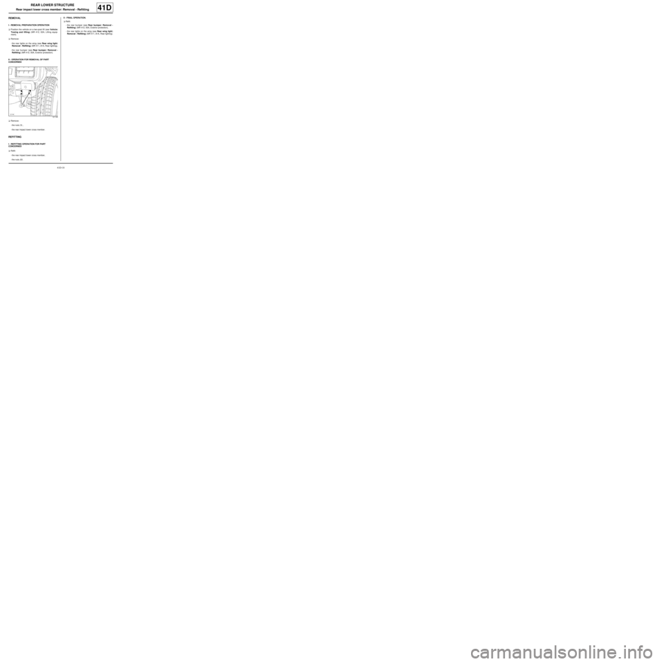
aRemove:
-the nuts (1) ,
-the rear impact lower cross member.
REFITTING
I - REFITTING OPERATION FOR PART
CONCERNED
aRefit:
-the rear impact lower cross member,
-the nuts (1) .II - FINAL OPERATION.
aRefit:
-the rear bumper (see Rear bumper: Removal -
Refitting) (MR 412, 55A, Exterior protection),
-the rear lights on the wing (see Rear wing light:
Removal - Refitting) (MR 411, 81A, Rear lighting).
121146
Page 112 of 209
42A-3
FRONT UPPER STRUCTURE
Front wing: Removal - Refitting
42A
REMOVAL
I - REMOVAL PREPARATION OPERATION
aRemove:
-the front wheel arch liner (see Front wheel arch
liner: Removal - Refitting) (MR 412, 55A, Exterior
protection),
-the front bumper (see Front bumper: Removal -
Refitting) (MR 412, 55A, Exterior protection),
-the halogen headlight (see Halogen headlight:
Removal - Refitting) (MR 411, 80B, Headlights).
II - REMOVAL OPERATION FOR PART
CONCERNED
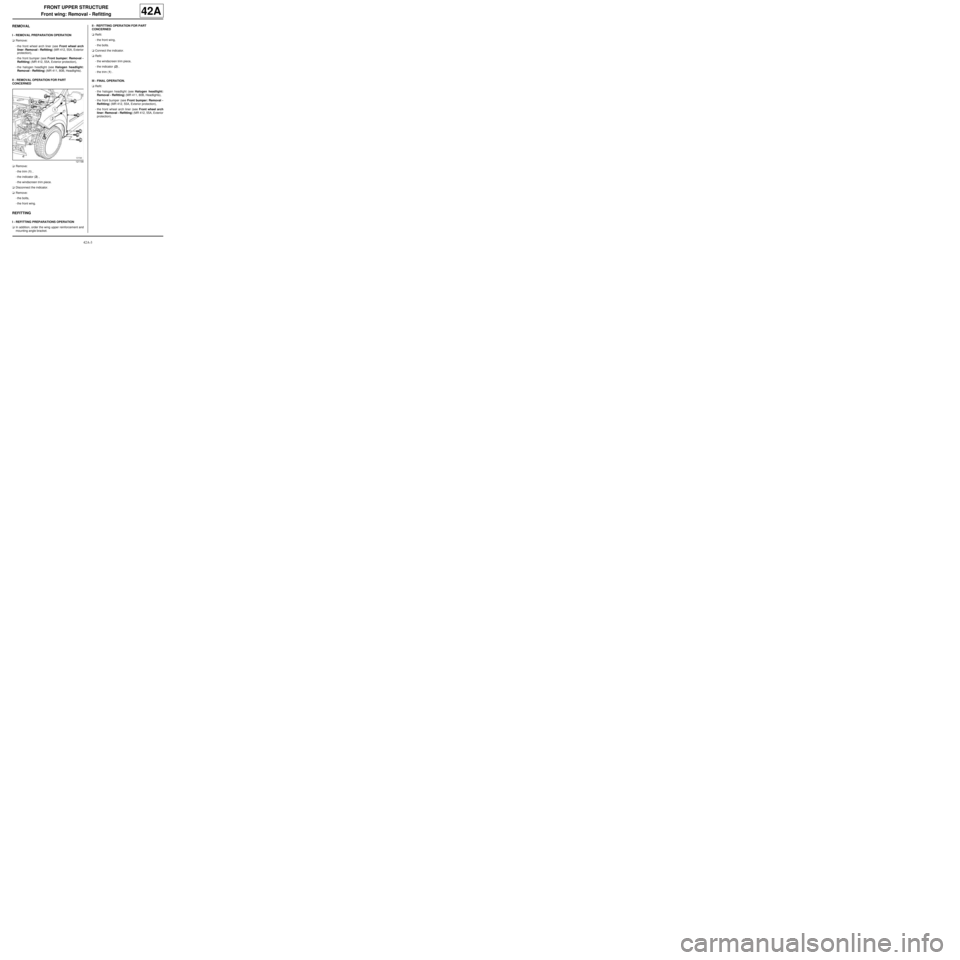
aRemove:
-the trim (1) ,
-the indicator (2) ,
-the windscreen trim piece.
aDisconnect the indicator.
aRemove:
-the bolts,
-the front wing.
REFITTING
I - REFITTING PREPARATIONS OPERATION
aIn addition, order the wing upper reinforcement and
mounting angle bracket.II - REFITTING OPERATION FOR PART
CONCERNED
aRefit:
-the front wing,
-the bolts.
aConnect the indicator.
aRefit:
-the windscreen trim piece,
-the indicator (2) ,
-the trim (1) .
III - FINAL OPERATION.
aRefit:
-the halogen headlight (see Halogen headlight:
Removal - Refitting) (MR 411, 80B, Headlights),
-the front bumper (see Front bumper: Removal -
Refitting) (MR 412, 55A, Exterior protection),
-the front wheel arch liner (see Front wheel arch
liner: Removal - Refitting) (MR 412, 55A, Exterior
protection).
121198
Page 116 of 209
42A-7
FRONT UPPER STRUCTURE
Front wing upper mounting support: Removal - Refitting42A
REMOVAL
I - REMOVAL PREPARATION OPERATION
aRemove:
-the front wheel arch liner (see Front wheel arch
liner: Removal - Refitting) (MR 412, 55A, Exterior
protection),
-the front bumper (see Front bumper: Removal -
Refitting) (MR 412, 55A, Exterior protection),
-the halogen headlight (see Halogen headlight:
Removal - Refitting) (MR 411, 80B, Headlights),
-the front wing (see 42A, Front upper structure,
Front wing: Removal - Refitting, page 42A-3) .
II - OPERATION FOR REMOVAL OF PART
CONCERNED
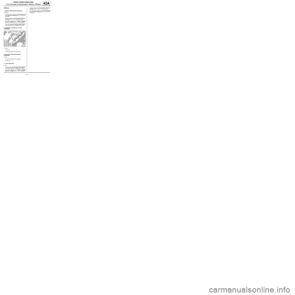
aRemove:
-the bolts (1) ,
-the front wing upper mounting support ,
III - REFITTING OPERATION FOR PART
CONCERNED
aRefit:
-the front wing upper mounting support,
-the bolts (1) .
IV - FINAL OPERATION.
aRefit:
-the front wing (see 42A, Front upper structure,
Front wing: Removal - Refitting, page 42A-3) ,
-the halogen headlight (see Halogen headlight:
Removal - Refitting) (MR 411, 80B, Headlights),-the front bumper (see Front bumper: Removal -
Refitting) (MR 412, 55A, Exterior protection),
-the front wheel arch liner (see Front wheel arch
liner: Removal - Refitting) (MR 412, 55A, Exterior
protection).
121237
Page 118 of 209
42A-9
FRONT UPPER STRUCTURE
Front end panel: Removal - Refitting
42A
REMOVAL
I - REMOVAL PREPARATION OPERATION
aRemove:
-the front bumper ( (see Front bumper: Removal -
Refitting) ),
-the headlights ( (see Halogen headlight: Remo-
val - Refitting) ),
-the bonnet catch ( (see Bonnet lock: Removal -
Refitting) ).
II - OPERATION FOR REMOVAL OF PART
CONCERNED
aUnclip the wiring harness.
aRemove the bonnet opening cable.
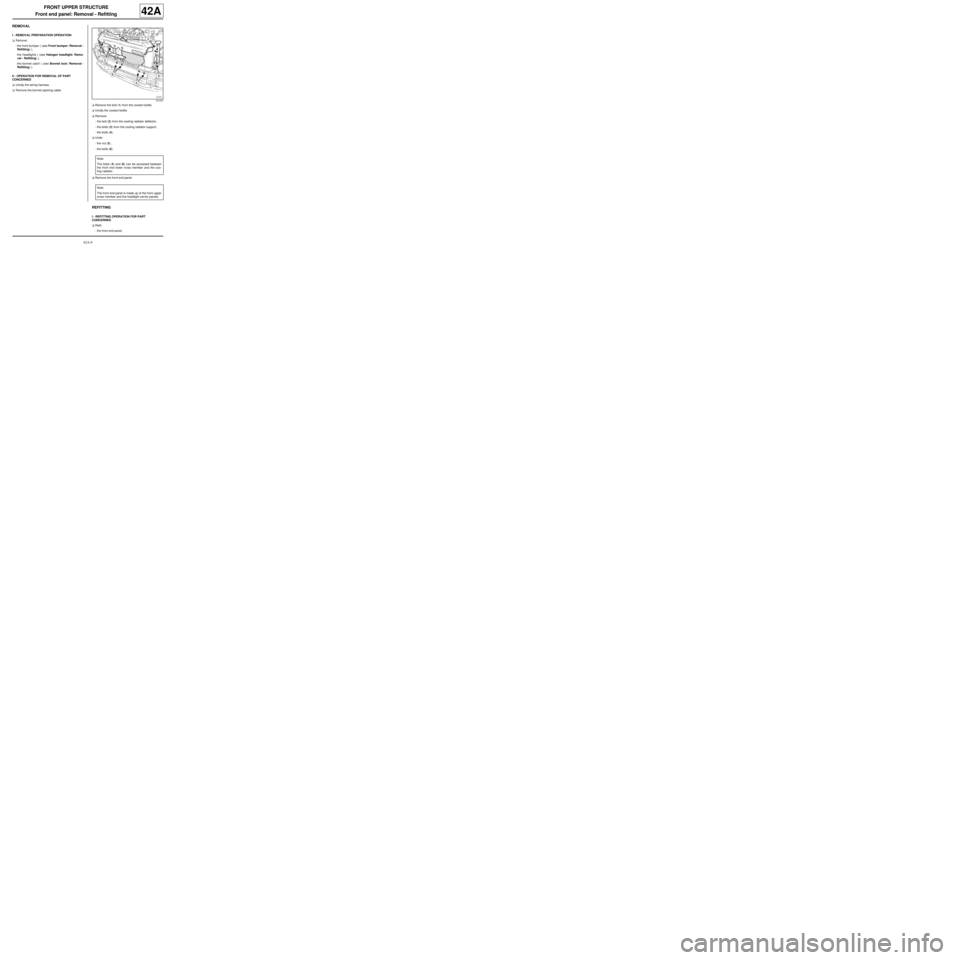
aRemove the bolt (1) from the coolant bottle.
aUnclip the coolant bottle.
aRemove:
-the bolt (2) from the cooling radiator deflector,
-the bolts (3) from the cooling radiator support,
-the bolts (4) .
aUndo:
-the nut (5) ,
-the bolts (6) .
aRemove the front end panel.
REFITTING
I - REFITTING OPERATION FOR PART
CONCERNED
aRefit:
-the front end panel,
121037
Note:
The bolts (4) and (6) can be accessed between
the front end lower cross member and the coo-
ling radiator.
Note:
The front end panel is made up of the front upper
cross member and the headlight carrier panels.
Page 119 of 209
42A-10
FRONT UPPER STRUCTURE
Front end panel: Removal - Refitting
42A
-the bolts (4) ,
-the bolts (3) on the cooling radiator support,
-the bolt (2) on the cooling radiator deflector.
aTighten:
-The bolts (6) ,
-the nut (5) .
aClip on the coolant bottle.
aRefit the bolt (1) on the coolant bottle.
aPosition the bonnet opening release cable.
aClip on the wiring harness.
II - FINAL OPERATION.
aRefit:
-the bonnet catch ( (see Bonnet lock: Removal -
Refitting) ),
-the headlights ( (see Halogen headlight: Remo-
val - Refitting) ),
-the front bumper ( (see Front bumper: Removal -
Refitting) ).
Page 120 of 209
42A-11
FRONT UPPER STRUCTURE
Headlight carrier panel: Removal - Refitting
42A
REMOVAL
I - REMOVAL PREPARATION OPERATION
aRemove:
-the front bumper (see Front bumper: Removal -
Refitting) (MR 412, 55A, Exterior protection),
-the halogen headlight (see Halogen headlight:
Removal - Refitting) (MR 411, 80B, Headlights),
-the bonnet catch (see Bonnet lock: Removal -
Refitting) (MR 412, 52A, Non-side opening ele-
ment mechanisms),
-the front upper cross member (see 42A, Front up-
per structure, Front upper cross member: Re-
moval - Refitting, page 42A-13) .
II - OPERATION FOR REMOVAL OF PART
CONCERNED
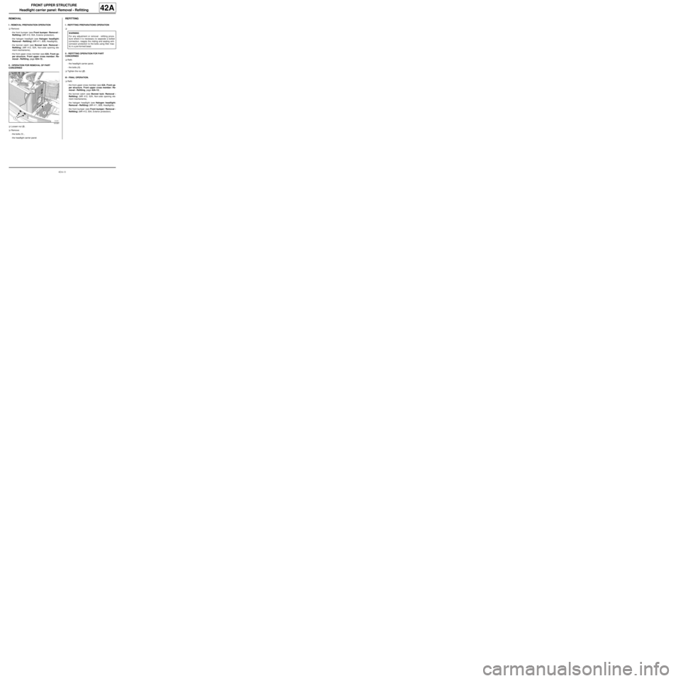
aLoosen nut (2) .
aRemove:
-the bolts (1) ,
-the headlight carrier panel.
REFITTING
I - REFITTING PREPARATIONS OPERATION
a
II - REFITTING OPERATION FOR PART
CONCERNED
aRefit:
-the headlight carrier panel,
-the bolts (1) .
aTighten the nut (2) .
III - FINAL OPERATION.
aRefit:
-the front upper cross member (see 42A, Front up-
per structure, Front upper cross member: Re-
moval - Refitting, page 42A-13) ,
-the bonnet catch (see Bonnet lock: Removal -
Refitting) (MR 412, 52A, Non-side opening ele-
ment mechanisms),
-the halogen headlight (see Halogen headlight:
Removal - Refitting) (MR 411, 80B, Headlights),
-the front bumper (see Front bumper: Removal -
Refitting) (MR 412, 55A, Exterior protection).
121251
WARNING
For any adjustment or removal - refitting proce-
dure where it is necessar y to separate a bolted
connection, reapply the mating and sealing anti-
corrosion protection to the bolts using filler mas-
tic in a pre-formed bead.
Page 122 of 209
42A-13
FRONT UPPER STRUCTURE
Front upper cross member: Removal - Refitting
42A
REMOVAL
I - REMOVAL PREPARATION OPERATION
aRemove:
-the front bumper ( (see Front bumper: Removal -
Refitting) ),
-the headlights ( (see Halogen headlight: Remo-
val - Refitting) ),
-the bonnet catch ( (see Bonnet lock: Removal -
Refitting) ).
II - OPERATION FOR REMOVAL OF PART
CONCERNED
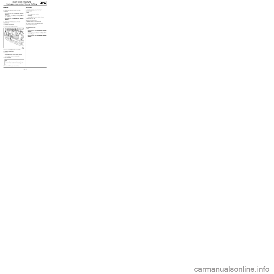
aUnclip the wiring harness.
aRemove the bonnet opening cable.
aRemove the bolt (1) from the coolant bottle.
aUnclip the coolant bottle.
aRemove:
-the bolt (2) from the cooling radiator deflector,
-the front upper cross member bolts (3) .
aUndo the bolts (4) .
aRemove the front upper cross member.
REFITTING
I - REFITTING OPERATION FOR PART
CONCERNED
aRefit:
-the front upper cross member,
-the bolts (3) ,
-the bolt (2) on the cooling radiator deflector.
aTighten the bolts (4) .
aClip on the coolant bottle.
aRefit the bolt (1) on the coolant bottle.
aPosition the bonnet opening release cable.
aClip on the wiring harness.
II - FINAL OPERATION.
aRefit:
-the bonnet catch ( (see Bonnet lock: Removal -
Refitting) ),
-the headlights ( (see Halogen headlight: Remo-
val - Refitting) ),
-the front bumper ( (see Front bumper: Removal -
Refitting) ).
121036
Note:
The bolts (4) can be accessed between the front
end lower cross member and the cooling radia-
tor.
Page 135 of 209
42A-26
FRONT UPPER STRUCTURE
Dashboard cross member: Removal - Refitting
42A
REMOVAL
a
I - REMOVAL PREPARATION OPERATION
aLock the airbag computer using the Diagnostic tool
(see Fault finding - Replacement of components)
(MR 413, 88C, Airbags and pretensioners).
aDisconnect the battery (see Battery: Removal - Re-
fitting) (MR 411, 80A, Battery).
aRemove:
-the dashboard (see Dashboard: Removal - Refit-
ting) (MR 412, 57A, Interior equipment),
-the steering column (see Steering column: Re-
moval - Refitting) (MR 411, 36A, Steering assem-
bly).II - OPERATION FOR REMOVAL OF PART
CONCERNED
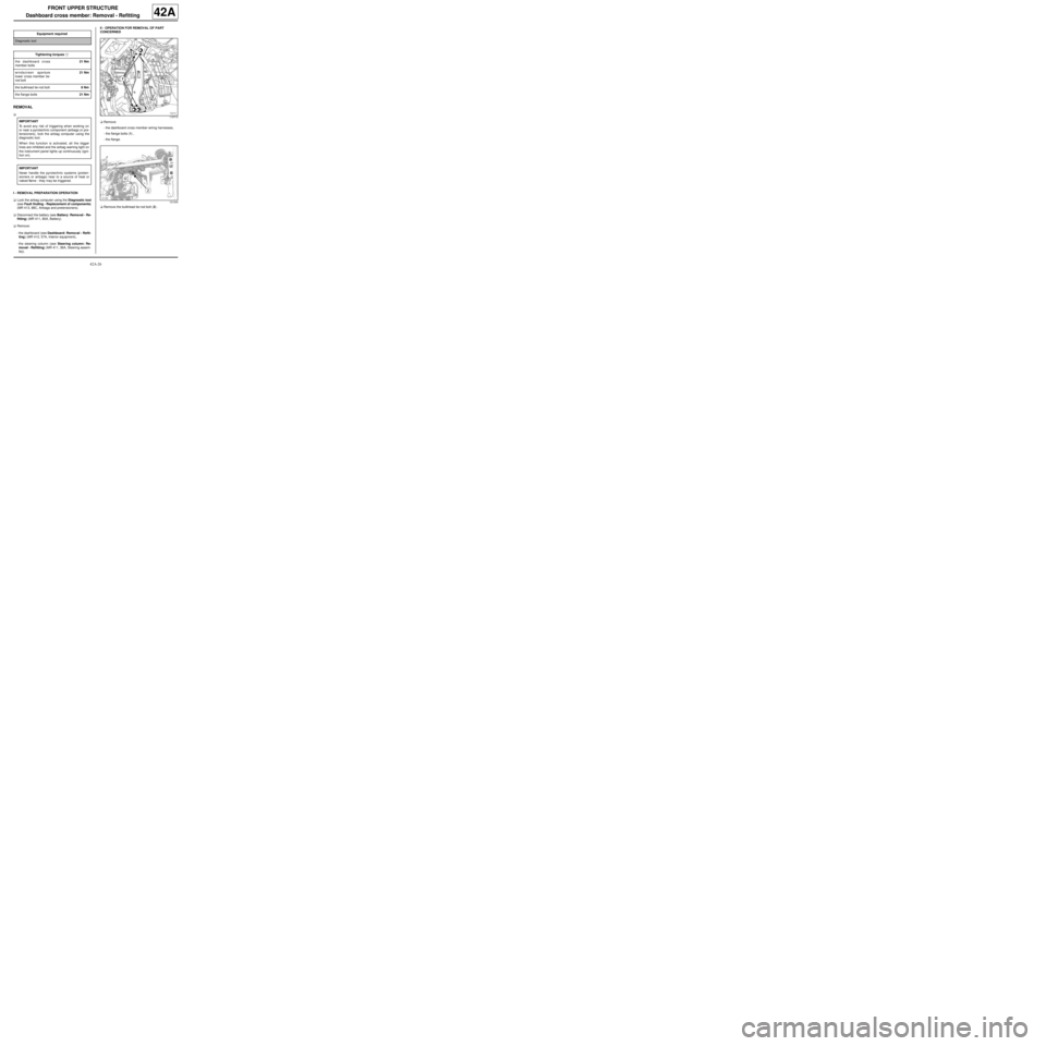
aRemove:
-the dashboard cross member wiring harnesses,
-the flange bolts (1) ,
-the flange.
aRemove the bulkhead tie-rod bolt (2) . Equipment required
Diagnostic tool
Tightening torquesm
the dashboard cross
member bolts21 Nm
windscreen aperture
lower cross member tie-
rod bolt21 Nm
the bulkhead tie-rod bolt8 Nm
the flange bolts21 Nm
IMPORTANT
To avoid any risk of triggering when working on
or near a pyrotechnic component (airbags or pre-
tensioners), lock the airbag computer using the
diagnostic tool.
When this function is activated, all the trigger
lines are inhibited and the airbag warning light on
the instrument panel lights up continuously (igni-
tion on).
IMPORTANT
Never handle the pyrotechnic systems (preten-
sioners or airbags) near to a source of heat or
naked flame - they may be triggered.
119713
121240