sensor RENAULT TWINGO RS 2009 2.G Transmission Workshop Manual
[x] Cancel search | Manufacturer: RENAULT, Model Year: 2009, Model line: TWINGO RS, Model: RENAULT TWINGO RS 2009 2.GPages: 135
Page 2 of 135
TWINGO - Chapitre 2
Contents
Pages
TWINGO - Chapitre 2ContentsPages
20A CLUTCH
Clutch: Precautions for the
repair 20A-1
Clutch: Specifications 20A-2
Pressure plate - Disc:
Removal - Refitting 20A-4
Clutch thrust bearing:
Removal - Refitting 20A-9
21A MANUAL GEARBOX
Manual gearbox oil:
Specifications 21A-1
Manual gearbox oils:
Draining - Filling 21A-2
Manual gearbox: List and
location of components 21A-4
Manual gearbox:
Identifi cation 21A-12
Manual gearbox:
Specifications 21A-14
Manual gearbox: Removal -
Refitting 21A-24
Manual gearbox: Repair 21A-34
Differential output seal:
Removal - Refitting 21A-38
Input shaft lip seal: Removal
- Refitting 21A-41
Reverse gear switch:
Removal - Refitting 21A-44
21B SEQUENTIAL GEARBOX
Sequential gearbox:
Precautions for the repair 21B-1
Sequential gearbox: List and
location of components 21B-2
Sequential gearbox oil:
Draining - Filling 21B-3
Pressure accumulator:
Removal - Refitting 21B-5
Pump assembly reservoir:
Removal - Refitting 21B-9
Electro-hydraulic unit:
Removal - Refitting 21B-11
Pump assembly: Removal -
Refitting 21B-18
Solenoid valves: Removal -
Refitting 21B-21
Engagement sensor :
Removal - Refitting 21B-27
Actuator module: Removal -
Refitting 21B-28
Gear selection sensor :
Removal - Refitting 21B-31 21A MANUAL GEARBOX
Page 3 of 135
Contents
Clutch position sensor :
Removal - Refitting 21B-34
Solenoid valve assembly
pressure sensor: Removal -
Refitting 21B-36
Sequential gearbox engine
speed sensor: Removal -
Refitting 21B-38
Sequential gearbox:
Removal - Refitting 21B-40
Sequential gearbox
converter: Removal -
Refitting 21B-47
Sequential gearbox gear
lever: Removal - Refitting 21B-48
29A DRIVESHAFTS
Driveshaft: Precautions for
the repair 29A-1
Front left-hand driveshaft:
Removal - Refitting 29A-2
Front right-hand driveshaft:
Removal - Refitting 29A-8
Relay shaft bearing:
Removal - Refitting 29A-13
Front driveshaft gaiter, wheel
side: Removal - Refitting 29A-14
Front right-hand driveshaft
gaiter, gearbox side:
Removal - Refitting 29A-18
Front left-hand driveshaft
gaiter, gearbox side:
Removal - Refitting 29A-23 21B SEQUENTIAL GEARBOX
Page 26 of 135
21A-11
MANUAL GEARBOX
Manual gearbox: List and location of components
JH1 or JH3 or JR5
21A
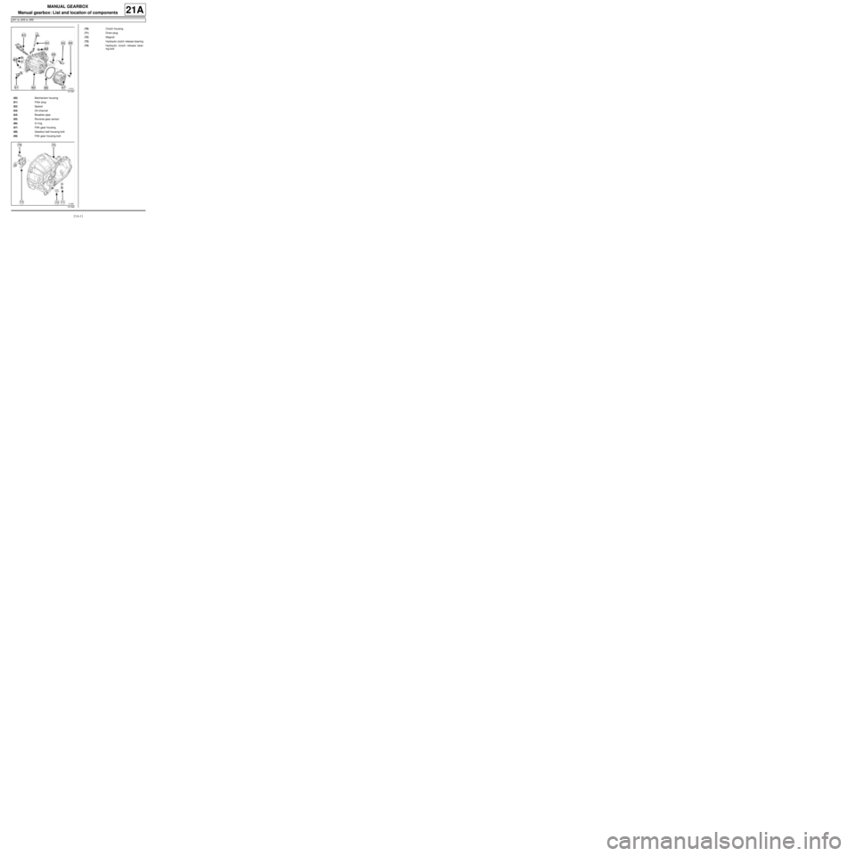
101391
(60) Mechanism housing
(61) Filler plug
(62) Spacer
(63) Oil channel
(64) Breather pipe
(65) Reverse gear sensor
(66) O-r ing
(67) Fifth gear housing
(68) Gearbox bell housing bolt
(69) Fifth gear housing bolt
101392
(70) Clutch housing
(71) Drain plug
(72) Magnet
(73) Hydraulic clutch release bearing
(74) Hydraulic clutch release bear-
ing bolt
Page 40 of 135
21A-25
MANUAL GEARBOX
Manual gearbox: Removal - Refitting
K9K, and JH3 or JR5
21A
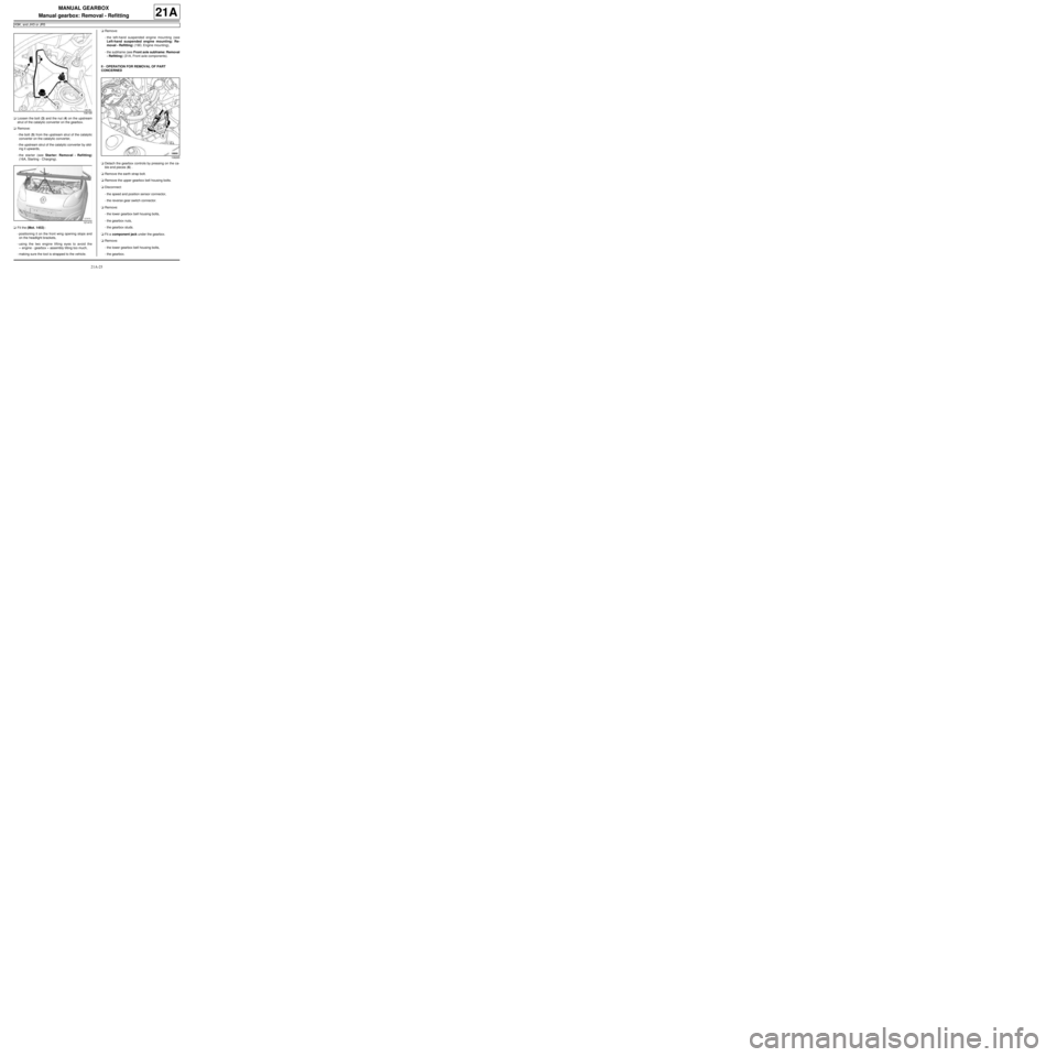
aLoosen the bolt (3) and the nut (4) on the upstream
strut of the catalytic converter on the gearbox.
aRemove:
-the bolt (5) from the upstream strut of the catalytic
converter on the catalytic converter,
-the upstream strut of the catalytic converter by slid-
ing it upwards,
-the starter (see Starter: Removal - Refitting)
(16A, Starting - Charging).
aFit the (Mot. 1453) :
-positioning it on the front wing opening stops and
on the headlight brackets,
-using the two engine lifting eyes to avoid the
« engine - gearbox » assembly tilting too much,
-making sure the tool is strapped to the vehicle.aRemove:
-the left-hand suspended engine mounting (see
Left-hand suspended engine mounting: Re-
moval - Refitting) (19D, Engine mounting),
-the subframe (see Front axle subframe: Removal
- Refitting) (31A, Front axle components).
II - OPERATION FOR REMOVAL OF PART
CONCERNED
aDetach the gearbox controls by pressing on the ca-
ble end pieces (6) .
aRemove the earth strap bolt.
aRemove the upper gearbox bell housing bolts.
aDisconnect:
-the speed and position sensor connector,
-the reverse gear switch connector.
aRemove:
-the lower gearbox bell housing bolts,
-the gearbox nuts,
-the gearbox studs.
aFit a component jack under the gearbox.
aRemove:
-the lower gearbox bell housing bolts,
-the gearbox.
106199
121415
108265
Page 41 of 135
21A-26
MANUAL GEARBOX
Manual gearbox: Removal - Refitting
K9K, and JH3 or JR5
21A
REFITTING
I - REFITTING OPERATION FOR PART
CONCERNED
aRefit:
-the gearbox using a component jack,
-the gearbox stud nuts,
-the gearbox lower bolts.
aTorque tighten:
-the lower gearbox bolts (44 N.m),
-the gearbox nuts and bolts (44 N.m).
aRefit the upper gearbox bolts.
aTorque tighten the gearbox upper bolts (44 N.m).
aRefit the earth strap bolt on the gearbox.
aConnect:
-the reverse gear switch connector,
-the speed and position sensor connector.
aClip the gearbox controls into place.
II - FINAL OPERATION
aRefit:
-the subframe (see Front axle subframe: Removal
- Refitting) (31A, Front axle components),
-the left-hand suspended engine mounting (see
Left-hand suspended engine mounting: Re-
moval - Refitting) (19D, Engine mounting).
aRemove the tool (Mot. 1453).
aRefit:
-the upstream strut of the catalytic converter by slid-
ing it upwards,
-the catalytic converter upstream strut bolt on the
catalytic converter.
aTighten the bolt and nut on the upstream strut of the
catalytic converter on the gearbox.
aRefit:
-the rear suspended engine mounting (see Lower
engine tie-bar: Removal - Refitting) (19D, En-
gine mounting),
-the hub carrier - front left-hand and front right-hand
driveshaft assemblies (see ) (31A, Front axle com-
ponents),
-the starter (see Starter: Removal - Refitting)
(16A, Starting - Charging),-the front left-hand wheel arch liner (see Front
wheel arch liner: Removal - Refitting) (55A, Ex-
terior protection),
-the front left-hand wheel (see Wheel: Removal -
Refitting) (35A, Wheels and tyres).
aClip:
-the union onto the hydraulic tappet slave cylinder,
-the hydraulic clutch control pipe,
-the gearbox breather.
aBleed the clutch (see Clutch circuit: Bleed) (37A,
Mechanical component controls).
aRefit the engine management computer mounting
fitted with the engine management computer.
aFit the engine management computer wiring har-
ness.
aRefit the engine management computer wiring har-
ness nut on the engine management computer
mounting.
aFit the engine management computer mounting.
aRefit:
-the engine management computer mounting bolts,
-the engine management computer mounting nuts.
aConnect the engine management computer connec-
tors.
aRefit:
-the scoop under the scuttle panel grille (see Scoop
under the scuttle panel grille: Removal - Refit-
ting) (56A, Exterior equipment),
-the scuttle panel grille (see Scuttle panel grille:
Removal - Refitting) (56A, Exterior equipment),
aFill up the gearbox oil (see 21A, Manual gearbox,
Manual gearbox oils: Draining - Filling, page
21A-2) .
aRefit:
-the battery tray (see Battery tray: Removal - Re-
fitting) (80A, Battery),
-the battery (see Battery: Removal - Refitting)
(80A, Battery).
Page 43 of 135
21A-28
MANUAL GEARBOX
Manual gearbox: Removal - Refitting
D4F, and JB1 – D7F, and JB1
21A
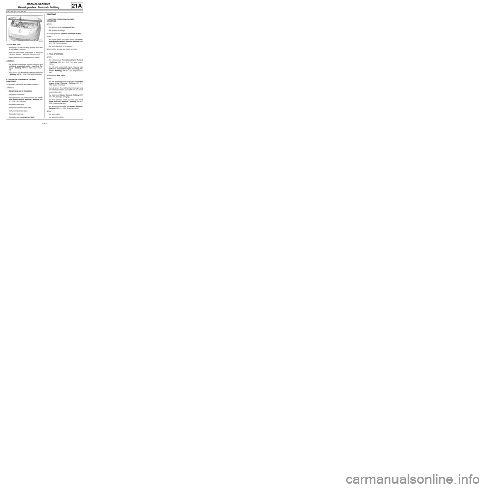
aFit the (Mot. 1453) :
-positioning it on the front wing opening stops and
on the headlight brackets,
-using the two engine lifting eyes to avoid the
« engine - gearbox » assembly tilting too much,
-making sure the tool is strapped to the vehicle.
aRemove:
-the left-hand suspended engine mounting (see
Left-hand suspended engine mounting: Re-
moval - Refitting) (MR 411, 19D, Engine mount-
ing),
-the subframe (see Front axle subframe: Removal
- Refitting) (MR 411, 31A, Front axle component).
II - OPERATION FOR REMOVAL OF PART
CONCERNED
aDisconnect the reverse gear switch connector.
aRemove:
-the earth strap bolt on the gearbox,
-the gearbox upper bolts,
-the engine speed and position sensor (see Crank-
shaft position sensor: Removal - Refitting) (MR
411, 17B, Petrol injection).
-the gearbox lower bolts,
-the flywheel protection plate bolts,
-the flywheel protection plate,
-the gearbox stud nuts,
-the gearbox using a component jack.
REFITTING
I - REFITTING OPERATION FOR PART
CONCERNED
aRefit:
-the gearbox using a component jack.
-the gearbox mountings.
aTorque tighten the gearbox mountings (44 Nm).
aRefit:
-the engine speed and position sensor (see Crank-
shaft position sensor: Removal - Refitting) (MR
411, 17B, Petrol injection),
-the earth strap bolt on the gearbox.
aConnect the reverse gear switch connector.
II - FINAL OPERATION.
aRefit:
-the subframe (see Front axle subframe: Removal
- Refitting) (MR 411, 31A, Front axle compo-
nents),
-the left-hand suspended engine mounting (see
Left-hand suspended engine mounting: Re-
moval - Refitting) (MR 411, 19D, Engine mount-
ing).
aRemove the (Mot. 1453).
aRefit:
-the rear suspended engine mounting (see Lower
engine tie-bar: Removal - Refitting) (MR 411,
19D, Engine mounting),
-the hub carrier - front left-hand and front right-hand
driveshaft assemblies (see ) (MR 411, 31A, Front
axle components),
-the starter (see Starter: Removal - Refitting) (MR
411, 16A, Starting - Charging),
-the front left-hand wheel arch liner (see Front
wheel arch liner: Removal - Refitting) (MR 412,
55A, Exterior protection),
-the left-hand front wheel (see Wheel: Removal -
Refitting) (MR 411, 35A, Wheels and tyres).
aClip:
-the clutch cable,
-the gearbox breather.
121415
Page 45 of 135
21A-30
MANUAL GEARBOX
Manual gearbox: Removal - Refitting
K4M, and JR5
21A
REMOVAL
I - REMOVAL PREPARATION OPERATION
aPosition the vehicle on a two-post lift (see Vehicle:
Towing and lifting) (02A, Lifting equipment).
aRemove:
-the engine undertray,
-the battery (see Battery: Removal - Refitting)
(80A, Battery),
-the air filter unit (see Air filter unit: Removal - Re-
fitting) (12A, Fuel mixture),
-the petrol injection computer (see Petrol injection
computer: Removal - Refitting) (17B, Petrol in-
jection),
-the battery tray (see Battery tray: Removal - Re-
fitting) (80A, Battery),
-the front wheels (see Wheel: Removal - Refitting)
(35A, Wheels and tyres),
-the front wheel arch liners (see Front wheel arch
liner: Removal - Refitting) (55A, Exterior protec-
tion),
-the front bumper (see Front bumper: Removal -
Refitting) (55A, Exterior protection).
aDrain:
-the gearbox (see 21A, Manual gearbox, Manual
gearbox oils: Draining - Filling, page 21A-2) ,
-the engine cooling system (see Cooling system:
Draining - Refilling) (19A, Cooling),
-the refrigerant circuit (see Refrigerant circuit:
Draining - Filling) (62A, Air conditioning).aRemove:
-the rear suspended engine mounting (see Lower
engine tie-bar: Removal - Refitting) (19D, En-
gine mounting),
-the front axle subframe (see Front axle subframe:
Removal - Refitting) (31A, Front axle compo-
nents),
-the front left-hand driveshaft (see 29A, Drive-
shafts, Front left-hand driveshaft: Removal -
Refitting, page 29A-2) ,
-the front right-hand driveshaft (see 29A, Drive-
shafts, Front right-hand driveshaft: Removal -
Refitting, page 29A-8) ,
-the differential output seals (see 21A, Manual
gearbox, Differential output seal: Removal - Re-
fitting, page 21A-38) (21A, Manual gearbox),
-the engine - gearbox assembly (see Engine -
gearbox assembly: Removal - Refitting) (10A,
Engine and peripherals).
II - OPERATION FOR REMOVAL OF PART
CONCERNED
aRemove the “engine - gearbox” assembly from
theusing a workshop hoist.
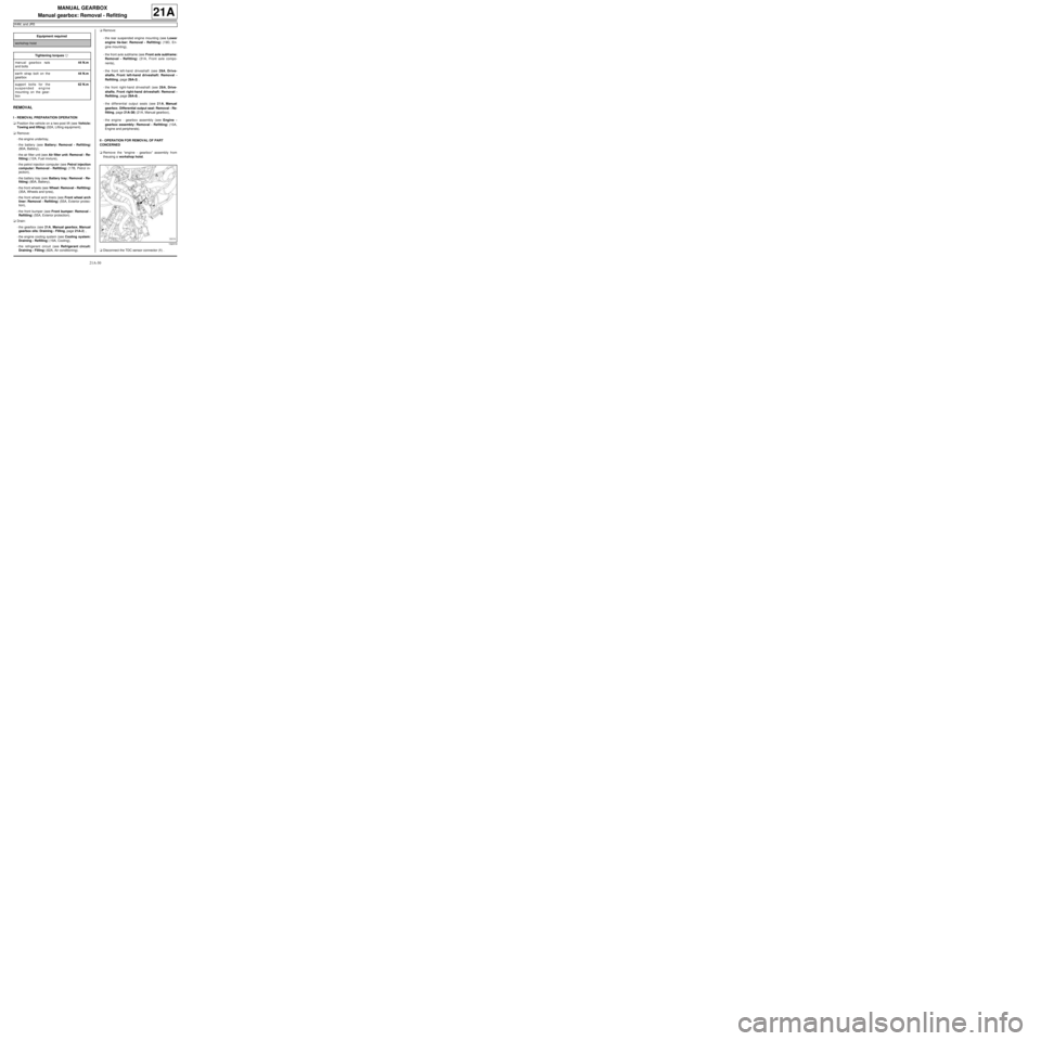
aDisconnect the TDC sensor connector (1) . Equipment required
workshop hoist
Tightening torquesm
manual gearbox nuts
and bolts44 N.m
earth strap bolt on the
gearbox44 N.m
support bolts for the
suspended engine
mounting on the gear-
box62 N.m
132319
Page 48 of 135
21A-33
MANUAL GEARBOX
Manual gearbox: Removal - Refitting
K4M, and JR5
21A
aFit the engine wiring.
aRefit:
-the starter (see Starter: Removal - Refitting)
(16A, Starting - Charging),
-the bolts of the engine wiring channel,
-the earth strap bolt on the gearbox.
aTorque tighten the earth strap bolt on the gearbox
(44 N.m).
aConnect the reverse gear switch connector.
aClip on the reverse gear switch.
aRefit the suspended engine mounting support on the
gearbox.
aTorque tighten the support bolts for the suspend-
ed engine mounting on the gearbox (62 N.m).
aConnect the TDC sensor connector.
aRefit the engine - gearbox assembly on the.
III - FINAL OPERATION
aRefit:
-the engine - gearbox assembly (see Engine -
gearbox assembly: Removal - Refitting) (10A,
Engine and peripherals),
-the differential output seals (see 21A, Manual
gearbox, Differential output seal: Removal - Re-
fitting, page 21A-38) (21A, Manual gearbox),
-the front right-hand driveshaft (see 29A, Drive-
shafts, Front right-hand driveshaft: Removal -
Refitting, page 29A-8) .
-the front left-hand driveshaft (see 29A, Drive-
shafts, Front left-hand driveshaft: Removal -
Refitting, page 29A-2) ,
-the front axle subframe (see Front axle subframe:
Removal - Refitting) (31A, Front axle compo-
nents),
-the rear suspended engine mounting (see Lower
engine tie-bar: Removal - Refitting) (19D, En-
gine mounting),
-the front bumper (see Front bumper: Removal -
Refitting) (55A, Exterior protection).
-the front wheel arch liners (see Front wheel arch
liner: Removal - Refitting) (55A, Exterior protec-
tion),
-the front wheels (see Wheel: Removal - Refitting)
(35A, Wheels and tyres),
-the battery tray (see Battery tray: Removal - Re-
fitting) (80A, Battery),-the petrol injection computer (see Petrol injection
computer: Removal - Refitting) (17B, Petrol in-
jection),
-the air filter unit (see Air filter unit: Removal - Re-
fitting) (12A, Fuel mixture),
-the battery (see Battery: Removal - Refitting)
(80A, Battery).
aRefill:
-the engine cooling system (see Cooling system:
Draining - Refilling) (19A, Cooling),
-the gearbox (see 21A, Manual gearbox, Manual
gearbox oils: Draining - Filling, page 21A-2) ,
-the refrigerant circuit (see Refrigerant circuit:
Draining - Filling) (62A, Air conditioning).
aRefit the engine undertray.
Page 61 of 135
21B-1
SEQUENTIAL GEARBOX
Sequential gearbox: Precautions for the repair
D4F, and JH1
21B
I - SEQUENTIAL GEARBOX
II - SEQUENTIAL GEARBOX COMPUTER
To disconnect the computer, switch off the ignition and
wait for 1 minute.
III - ELECTRO-HYDRAULIC UNIT
Discharge the pressure accumulator using the Diag-
nostic tool before any operation on the electro-hy-
draulic unit.
Be careful not to twist the high pressure pipes when re-
moving the electro-hydraulic unit.
IV - GEAR SELECTION SENSOREquipment required
Diagnostic tool
IMPORTANT
Before any operation on the sequential system, dis-
charge the accumulator using the Diagnostic tool.
WARNING
If any operation is carried out on the electro-hydrau-
lic unit, it is essential to clean the unit using a clean-
ing product and compressed air.
Never leave the circuit open and never use a high
pressure cleaner.
WARNING
After the accumulator has been fully filled (15 sec-
onds after the ignition has been switched on): the
oil level is at the MINIMUM mark.
WARNING
To remove the gear selection sensor it is essential
that you shift to first gear before removal.
Page 62 of 135
21B-2
SEQUENTIAL GEARBOX
Sequential gearbox: List and location of components
D4F, and JH1
21B
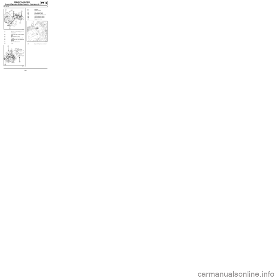
122171
(1) Actuator module high pressure
supply pipe
(2) Clutch stay high pressure supply
pipe
(3) Reservoir retur n hose
(4) Engagement solenoid v alve 2
(5) Solenoid valve unit pressure
sensor
(6) Clutch position sensor
(7) Tank
122172
(8) Pump unit
(9) Actuator module
(10) Gear selection sensor
(11) Clutch solenoid valve
(12) Engagement solenoid valve 1
(13) Selection solenoid valve 3
(14) Selection solenoid valve 4
(15) Engagement sensor
122160
(16) Sequential gearbox speed sen-
sor