eco RENAULT ZOE 2017 1.G Service Manual
[x] Cancel search | Manufacturer: RENAULT, Model Year: 2017, Model line: ZOE, Model: RENAULT ZOE 2017 1.GPages: 220, PDF Size: 4.07 MB
Page 104 of 220

2.10
VEHICLE RANGE: recommendations (1/2)
A “sporty” driving style reduces your
vehicle range: opt for a “lighter” driving
style.
Advice:
– drive at a constant speed.
– keep an eye on the tools available to you to view the road conditions
(charge meter, current consump-
tion, journey log, etc). Please refer
to the information on “Eco-driving” in
Section 2;– adapt your driving style to avoid ex- cessive energy consumption
– favour power recovery: anticipate traffic changes by lifting your foot off
the accelerator pedal or by braking
gradually.
Road type
Do not try to maintain the same speed
up a hill, accelerate no more than you
would on the level. Keep your foot in
the same position on the accelerator
pedal.
The vehicle range is approved for a
mixed NEDC cycle (New European
Driving Cycle).
In real usage, the range of an electric
vehicle may vary depending on several
factors over which you have partial con-
trol, which may make a considerable
difference to the vehicle range. These
factors are:
– speed and driving style;
– type of road;
– heating level;
– tyres;
– use of electrical accessories;
– vehicle loading.
Furthermore, activating ECO mode en-
ables the vehicle to automatically take
charge of all energy consuming ele-
ments (engine power, heating, etc.) to
reduce their consumption to the fullest
possible extent. Please refer to the in-
formation on “Eco-driving” in Section 2.
Speed and driving style
High speeds will reduce your vehicle’s
range.
Page 105 of 220

2.11
VEHICLE RANGE: recommendations (2/2)
Heating levels
The use of heating or air-conditioning
reduces vehicle range.
To maintain your vehicle range, you are
recommended to favour:
– before using the vehicle, the “pro-gramming” mode (please refer to the
information in “Air-conditioning: pro-
gramming” in Section 3).
– while driving, the ECO mode (please see information about “ECO driving”
in Section 2).
Tyres
An under-inflated tyre increases energy
consumption. Comply with the speci-
fied tyre pressures for your vehicle.
When driving, use tyres made by the
same manufacturer, with the same di-
mensions, type and structure as the
original tyres. The use of non-regula-
tion tyres significantly reduces vehicle
range.
Please see the information on “Tyre
pressure” in Section 4.
Vehicle loading
Avoid pointlessly overloading your ve-
hicle.
Page 106 of 220
2.12
ENVIRONMENT
Please make your own
contribution towards
protecting the environment
too.
– Worn parts replaced in the course of routine vehicle maintenance (sec-
ondary 12 V battery, batteries, etc.)
must be disposed of through special-
ist organisations.
– At the end of the vehicle’s service life, it should be sent to approved
centres to ensure that it is recycled.
– In all cases, comply with local legis- lation.
Recycling
Your vehicle is 85% recyclable and
95% recoverable.
To achieve these objectives, many of
the vehicle components have been de-
signed to enable them to be recycled.
The materials and structures have
been carefully designed to allow these
components to be easily removed and
reprocessed by specialist companies.
In order to preserve raw material re-
sources, this vehicle incorporates nu-
merous parts made from recycled plas-
tics or renewable materials (vegetable
or animal-derived materials such as
cotton or wool).
Your vehicle has been designed with
respect for the environment in mind for
its entire service life: during production,
use and at the end of its life.
This commitment is illustrated by the
Renault eco² group signature.
Manufacture
Your vehicle has been manufactured at
an industrial site which uses a progress
policy to reduce environmental impacts
on rivers and natural areas (reduc-
tion of water and energy consumption,
visual and noise pollution, atmospheric
emissions and waste water, sorting and
reusing waste).
Page 107 of 220
2.13
TYRE PRESSURE LOSS WARNING (1/3)
1
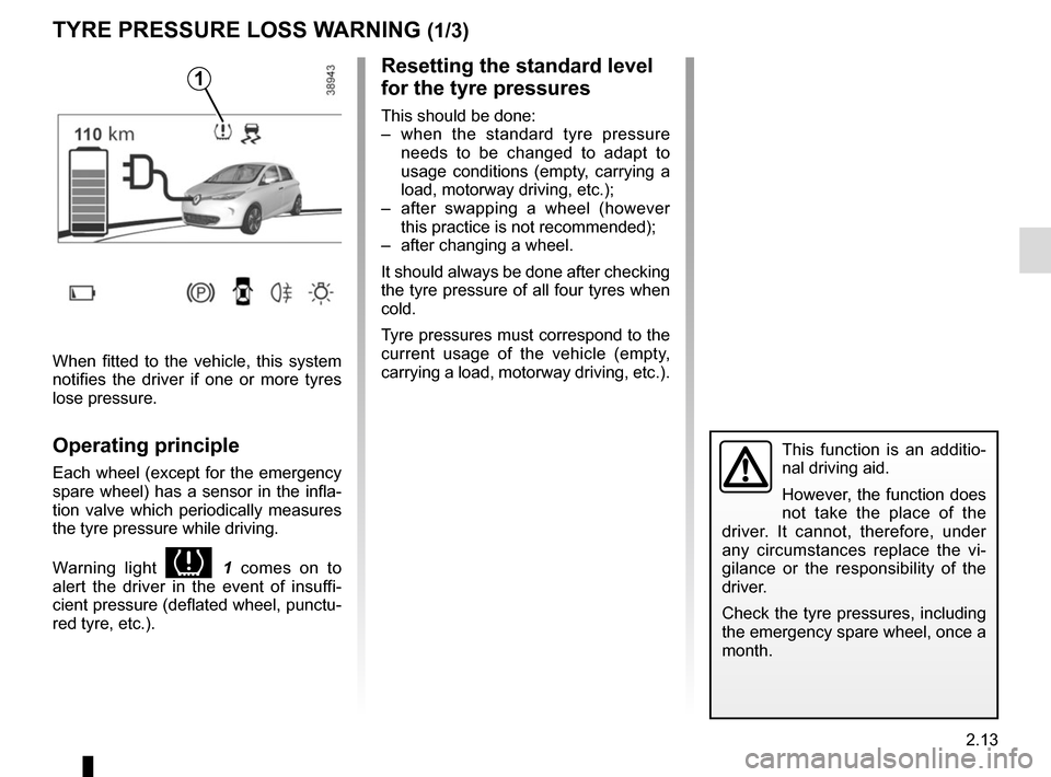
When fitted to the vehicle, this system
notifies the driver if one or more tyres
lose pressure.
Operating principle
Each wheel (except for the emergency
spare wheel) has a sensor in the infla-
tion valve which periodically measures
the tyre pressure while driving.
Warning light
1 comes on to
alert the driver in the event of insuffi-
cient pressure (deflated wheel, punctu-
red tyre, etc.).
Resetting the standard level
for the tyre pressures
This should be done:
– when the standard tyre pressure needs to be changed to adapt to
usage conditions (empty, carrying a
load, motorway driving, etc.);
– after swapping a wheel (however this practice is not recommended);
– after changing a wheel.
It should always be done after checking
the tyre pressure of all four tyres when
cold.
Tyre pressures must correspond to the
current usage of the vehicle (empty,
carrying a load, motorway driving, etc.).
This function is an additio-
nal driving aid.
However, the function does
not take the place of the
driver. It cannot, therefore, under
any circumstances replace the vi-
gilance or the responsibility of the
driver.
Check the tyre pressures, including
the emergency spare wheel, once a
month.
Page 108 of 220
2.14
TYRE PRESSURE LOSS WARNING (2/3)
2
3
4
Note:
The standard tyre pressure cannot be
less than that recommended and indi-
cated on the door frame.
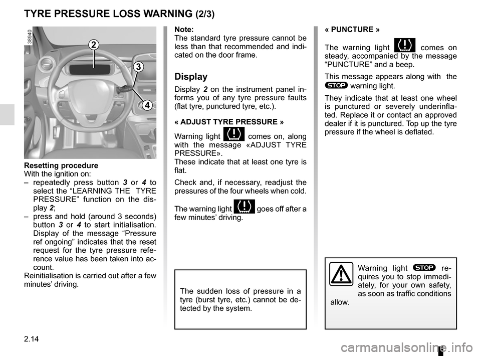
Display
Display 2 on the instrument panel in-
forms you of any tyre pressure faults
(flat tyre, punctured tyre, etc.).
« ADJUST TYRE PRESSURE »
Warning light
comes on, along
with the message «ADJUST TYRE
PRESSURE».
These indicate that at least one tyre is
flat.
Check and, if necessary, readjust the
pressures of the four wheels when cold.
The warning light
goes off after a
few minutes’ driving.
« PUNCTURE »
The warning light
comes on
steady, accompanied by the message
“PUNCTURE” and a beep.
This message appears along with the
® warning light.
They indicate that at least one wheel
is punctured or severely underinfla-
ted. Replace it or contact an approved
dealer if it is punctured. Top up the tyre
pressure if the wheel is deflated.
Warning light ® re-
quires you to stop immedi-
ately, for your own safety,
as soon as traffic conditions
allow.
Resetting procedure
With the ignition on:
– repeatedly press button 3 or 4 to
select the “LEARNING THE TYRE
PRESSURE” function on the dis-
play 2;
– press and hold (around 3 seconds) button 3 or 4 to start initialisation.
Display of the message “Pressure
ref ongoing” indicates that the reset
request for the tyre pressure refe-
rence value has been taken into ac-
count.
Reinitialisation is carried out after a few
minutes’ driving.
The sudden loss of pressure in a
tyre (burst tyre, etc.) cannot be de-
tected by the system.
Page 109 of 220
2.15
TYRE PRESSURE LOSS WARNING (3/3)
“CHECK TYRE PRESSURE SENSORS
The warning light
flashes for
several seconds, then stays on, along
with the message “CHECK TYRE
PRESSURE SENSORS”.
This message appears along with the
© warning light.
They indicate that at least one tyre is
not fitted with sensors (e.g. emergency
spare wheel). Otherwise, consult an
authorised dealer.
Readjustment of tyre
pressures
The tyre pressures must be adjusted
when cold (please refer to the label lo-
cated on the edge of the driver’s door).
If tyre pressures cannot be checked
when the tyres are cold, the recom-
mended pressures must be increased
by 0.2 to 0.3 bar (3 PSI).
Never deflate a hot tyre.
Changing a wheel
The system may take sev-
eral minutes depending on
use for the new wheel pres-
sures to be recognised; check the
tyre pressures after all operations.
Tyre repair product and
inflation kit
Because the valves are specially desi-
gned, only use equipment approved by
the approved network. Please refer to
“Tyre inflation kit” in Section 5.
Replacing wheels/tyres
This system requires specific equip-
ment (wheels, tyres, hubcaps, etc.).
Please see the information on “Tyres”
in Section 5.
Contact an approved Dealer to fit new
tyres and to find out about available ac-
cessories compatible with the system
and available from your dealer network:
the use of any other accessory could
affect the correct operation of the
system or damage a sensor.
Emergency spare wheel
If the vehicle is equipped with an emer-
gency spare wheel, it will not have a
sensor. When it is fitted on the vehicle,
the warning light
flashes for se-
veral seconds, then stays on, together
with the warning light
© and the
message “CHECK TYRE PRESSURE
SENSORS” appears on the instrument
panel.
Page 113 of 220
2.19
The hill start assistance
system cannot completely
prevent the vehicle from rol-
ling backwards in all situa-
tions (extremely steep gradients,
etc.).
In all cases, the driver may depress
the brake pedal to prevent the vehi-
cle from rolling backwards.
The hill start assistance function
should not be used for prolonged
stops: use the brake pedal.
This function is not designed to im-
mobilise the vehicle permanently.
If necessary, use the brake pedal to
stop the vehicle.
The driver must remain particularly
vigilant when driving on slippery or
low-grip surfaces and/or on hills.
Risk of serious injury.
Hill start assistance
Depending on the gradient of the in-
cline, this system assists the driver
when starting on a hill. It prevents the
vehicle from rolling backwards by au-
tomatically applying the brakes when
the driver lifts his/her foot off the brake
pedal to depress the accelerator pedal.
System operation
It only operates when the gear lever is
in a position other than neutral (other
than N or P) and the vehicle is comple-
tely stationary (brake pedal depressed).
The system holds the vehicle for ap-
proximately 2 seconds. The brakes are
then gradually released (the vehicle will
move according to the slope).
DRIVER CORRECTION DEVICES/AIDS (4/5)
Page 114 of 220
2.20
Regenerative braking system
When braking, the regenerative braking
system can convert the energy pro-
duced by the vehicle deceleration into
electric energy.
This will recharge the 400V traction bat-
tery and gain greater vehicle range.Operating faults
– © lights up on the instrument
panel, alongside the message
“Check braking system”: braking as-
sistance is available at all times.
Under these conditions, the feel of
applying the brake pedal may be dif-
ferent.
You are recommended to apply
strong continuous pressure to the
pedal.
Please see an authorised dealer.
–
û lights up on the instrument
panel, alongside the message
“Braking system fault”: this indi-
cates a fault in the braking system.
Please call an authorised dealer.
DRIVER CORRECTION DEVICES/AIDS (5/5)
The û warning light
requires you to stop imme-
diately, for your own safety,
as soon as traffic conditions allow.
Switch off the engine and do not res-
tart it. Contact an Authorised Dealer.
Page 120 of 220
2.26
CRUISE CONTROL (3/4)
The cruise control function
is in no way linked to the
braking system.
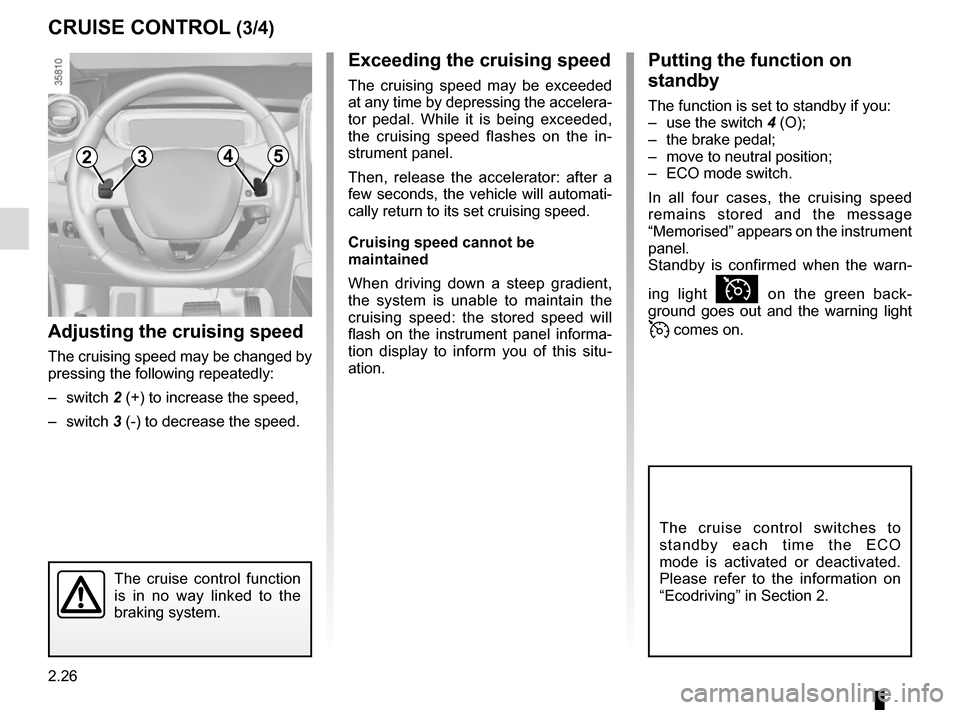
Adjusting the cruising speed
The cruising speed may be changed by
pressing the following repeatedly:
– switch 2 (+) to increase the speed,
– switch 3 (-) to decrease the speed.
Exceeding the cruising speed
The cruising speed may be exceeded
at any time by depressing the accelera-
tor pedal. While it is being exceeded,
the cruising speed flashes on the in-
strument panel.
Then, release the accelerator: after a
few seconds, the vehicle will automati-
cally return to its set cruising speed.
Cruising speed cannot be
maintained
When driving down a steep gradient,
the system is unable to maintain the
cruising speed: the stored speed will
flash on the instrument panel informa-
tion display to inform you of this situ-
ation.
2354
Putting the function on
standby
The function is set to standby if you:
– use the switch 4 (O);
– the brake pedal;
– move to neutral position;
– ECO mode switch.
In all four cases, the cruising speed
remains stored and the message
“Memorised” appears on the instrument
panel.
Standby is confirmed when the warn-
ing light
Ï on the green back-
ground goes out and the warning light
comes on.
The cruise control switches to
standby each time the ECO
mode is activated or deactivated.
Please refer to the information on
“Ecodriving” in Section 2.
Page 122 of 220
2.28
PARKING DISTANCE CONTROL (1/2)
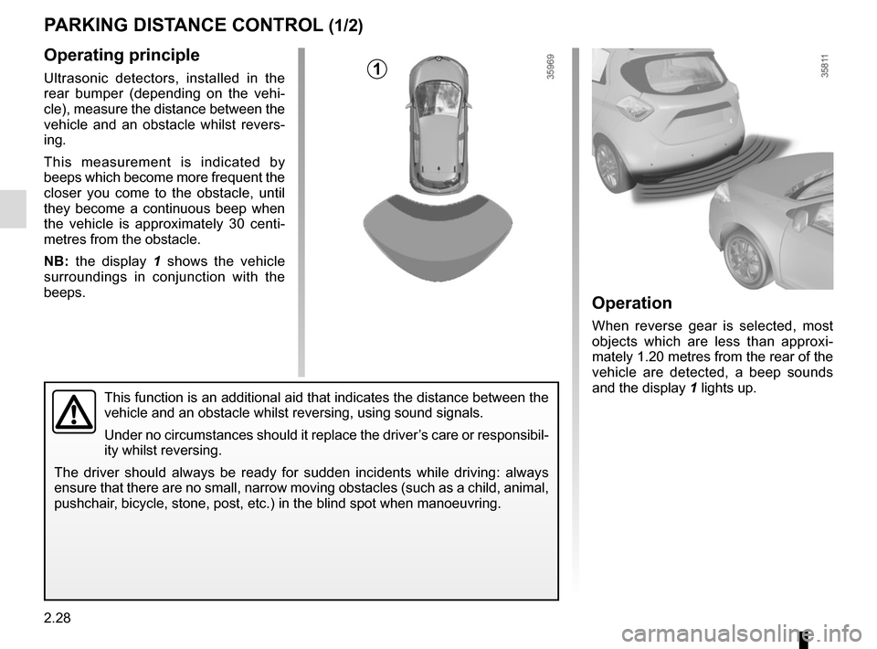
Operating principle
Ultrasonic detectors, installed in the
rear bumper (depending on the vehi-
cle), measure the distance between the
vehicle and an obstacle whilst revers-
ing.
This measurement is indicated by
beeps which become more frequent the
closer you come to the obstacle, until
they become a continuous beep when
the vehicle is approximately 30 centi-
metres from the obstacle.
NB: the display 1 shows the vehicle
surroundings in conjunction with the
beeps.
This function is an additional aid that indicates the distance between t\
he
vehicle and an obstacle whilst reversing, using sound signals.
Under no circumstances should it replace the driver’s care or responsibil-
ity whilst reversing.
The driver should always be ready for sudden incidents while driving: al\
ways
ensure that there are no small, narrow moving obstacles (such as a chil\
d, animal,
pushchair, bicycle, stone, post, etc.) in the blind spot when manoeuvring.
Operation
When reverse gear is selected, most
objects which are less than approxi-
mately 1.20 metres from the rear of the
vehicle are detected, a beep sounds
and the display 1 lights up.
1