gearbox Seat Alhambra 2011 Owner's Manual
[x] Cancel search | Manufacturer: SEAT, Model Year: 2011, Model line: Alhambra, Model: Seat Alhambra 2011Pages: 385, PDF Size: 7.92 MB
Page 56 of 385
54
Cockpit
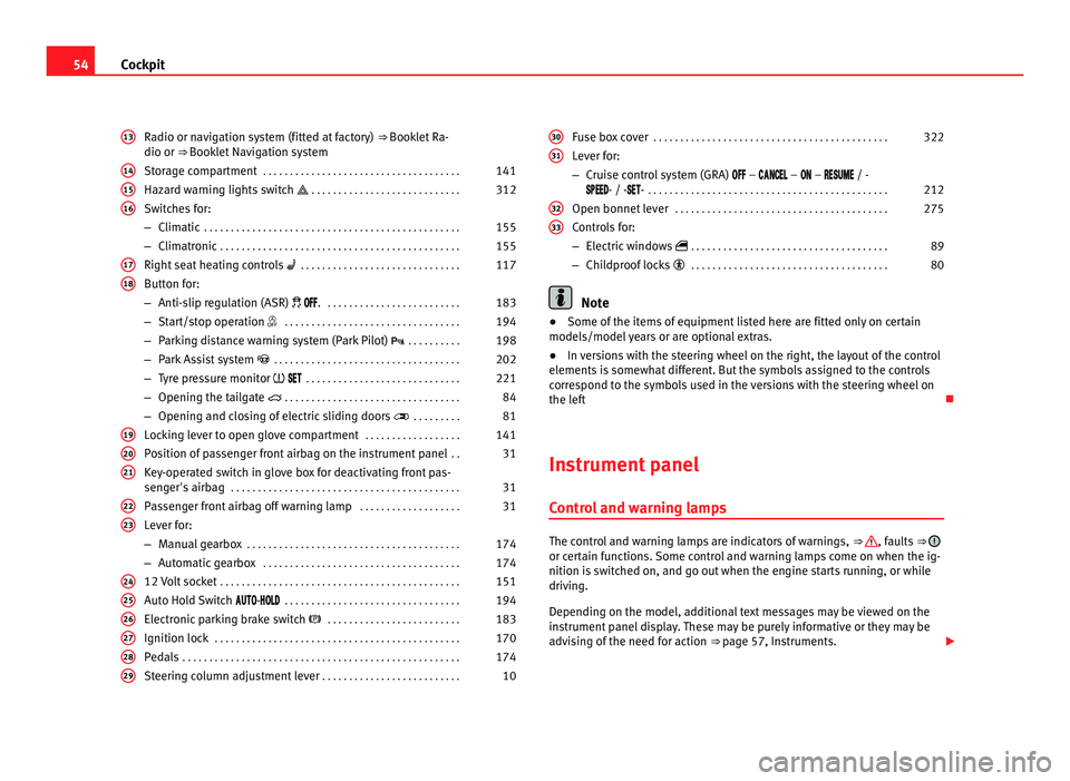
Radio or navigation system (fitted at factory) ⇒ Booklet Ra-
dio or ⇒ Booklet Navigation system
Storage compartment . . . . . . . . . . . . . . . . . . . . . . . . . . . . . . . . . . . . . 141
Hazard warning lights switch . . . . . . . . . . . . . . . . . . . . . . . . . . . . 312
Switches for:
– Climatic . . . . . . . . . . . . . . . . . . . . . . . . . . . . . . . . . . . . . . . . . . . . . . . . 155
– C
limatronic . . . . . . . . . . . . . . . . . . . . . . . . . . . . . . . . . . . . . . . . . . . . . 155
Right se
at heating controls . . . . . . . . . . . . . . . . . . . . . . . . . . . . . . 117
Button for:
– Anti-slip r
egulation (ASR) . . . . . . . . . . . . . . . . . . . . . . . . . . 183
– Start/stop operation . . . . . . . . . . . . . . . . . . . . . . . . . . . . . . . . . 194
– Parking distance warning system (Park Pilot) . . . . . . . . . . 198
– Park Assist system . . . . . . . . . . . . . . . . . . . . . . . . . . . . . . . . . . . 202
– Tyre pressure monitor
. . . . . . . . . . . . . . . . . . . . . . . . . . . . . 221
– Opening the tailgate . . . . . . . . . . . . . . . . . . . . . . . . . . . . . . . . . 84
– Opening and closing of electric sliding doors . . . . . . . . . 81
Loc
king lever to open glove compartment . . . . . . . . . . . . . . . . . .141
Position of passenger front airbag on the instrument panel . .31
Key-operated switch in glove box for deactivating front pas-
senger's
airbag . . . . . . . . . . . . . . . . . . . . . . . . . . . . . . . . . . . . . . . . . . . 31
Passenger front airbag off warning lamp . . . . . . . . . . . . . . . . . . .31
Lever for:
– Manual g
earbox . . . . . . . . . . . . . . . . . . . . . . . . . . . . . . . . . . . . . . . . 174
– Automatic gearbox . . . . . . . . . . . . . . . . . . . . . . . . . . . . . . . . . . . . . 174
12 V
olt socket . . . . . . . . . . . . . . . . . . . . . . . . . . . . . . . . . . . . . . . . . . . . . 151
Auto Hold Switch - . . . . . . . . . . . . . . . . . . . . . . . . . . . . . . . . . 194
Electr
onic parking brake switch . . . . . . . . . . . . . . . . . . . . . . . . . 183
Ignition lock . . . . . . . . . . . . . . . . . . . . . . . . . . . . . . . . . . . . . . . . . . . . . . 170
Pedals . . . . . . . . . . . . . . . . . . . . . . . . . . . . . . . . . . . . . . . . . . . . . . . . . . . . 174
Steering column adjustment lever . . . . . . . . . . . . . . . . . . . . . . . . . . 10
13 14
15
16
17
18
19
20
21
22
23
24
25
26
27
28
29 Fuse box cover
. . . . . . . . . . . . . . . . . . . . . . . . . . . . . . . . . . . . . . . . . . . . 322
Lever for:
– Crui se c
ontrol system (GRA) – – – / -
- / -- . . . . . . . . . . . . . . . . . . . . . . . . . . . . . . . . . . . . . . . . . . . . . 212
Open bonnet lever . . . . . . . . . . . . . . . . . . . . . . . . . . . . . . . . . . . . . . . . 275
Controls for:
– Electric w
indows . . . . . . . . . . . . . . . . . . . . . . . . . . . . . . . . . . . . . 89
– Childproof locks . . . . . . . . . . . . . . . . . . . . . . . . . . . . . . . . . . . . . 80 Note
● Some of the items of equipment listed here are fitted only on certain
model s/model
years or are optional extras.
● In versions with the steering wheel on the right, the layout of the control
elements i
s somewhat different. But the symbols assigned to the controls
correspond to the symbols used in the versions with the steering wheel on
the left
Instrument panel Contro
l and warning lamps The control and warning lamps are indicators of warnings,
⇒ , faults
⇒ or certain functions. Some control and warning lamps come on when the ig-
nition is
sw
itched on, and go out when the engine starts running, or while
driving.
Depending on the model, additional text messages may be viewed on the
instrument panel display. These may be purely informative or they may be
advising of the need for action ⇒ page 57, Instruments.
30 31
32
33
Page 59 of 385
57
Cockpit
Instruments Introduction Additional information and warnings:
●
Indicator lamps ⇒ pag e 54
● Gear engaged display (automatic gearbox) ⇒ pag
e 174.
● Instructions for inspection intervals ⇒ Booklet
Maintenance Programme WARNING
Any distraction may lead to an accident, with the risk of injury.
● Do not handle the instrument panel controls when driving.
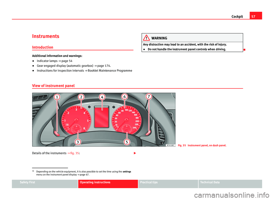
View of instrument panel Fig. 35 Instrument panel, on dash panel.
Details of the instruments ⇒ fig. 35: 1)
Depending on the vehicle equipment, it is also possible to set the time using the settings
menu on the in
strument panel display ⇒ page 67.Safety First Operating instructions Practical tips Technical Data
Page 60 of 385
58
Cockpit
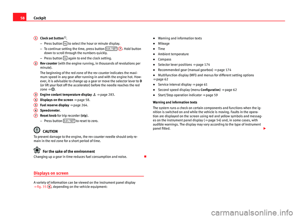
Clock set button 1)
.
– Pre s
s button to select the hour or minute display.
– To c ontinue settin
g the time, press button 0.0 / SET
7 . Hold button
down t o s
croll through the numbers quickly.
– Press button again to end the clock setting.
Rev c
ounter (with the engine running, in thousands of revolutions per
minute).
The beginning of the red zone of the rev counter indicates the maxi-
mum speed in any gear after running-in and with the engine hot. How-
ever, it is advisable to change up a gear or move the selector lever to D
(or lift your foot off the accelerator) before the needle reaches the red
zone ⇒ .
Engine c oo
lant temperature display ⇒ page 283.
Displays on the screen ⇒ page 58.
Fuel reserve display ⇒ page 264.
Speedometer.
Reset knob for trip recorder (trip).
– Press button 0.0 / SET to reset to zero.
CAUTION
To prevent damage to the engine, the rev counter needle should only re-
main in the r ed
zone for a short period of time. For the sake of the environment
Changing up a gear in time reduces fuel consumption and noise.
Displays on screen A variety of information can be viewed on the instrument panel display
⇒
fig. 35 4 , depending on the vehicle equipment:
1
2
3
4
5
6
7 ●
Warning and information texts
● Mil
eage
● Time
● Ambient temperature
● Compass
● Selector lever positions ⇒ page 174
● R
ecommended gear (manual gearbox) ⇒ page 174
● M
ultifunction display (MFI) and menus for different setting options
⇒ page 62
● Ser
vice interval display ⇒ page 61
● Sec
ond speed display (menu Configuration
) ⇒ page 62
● Start/Stop operation indicator ⇒ pag
e 59
Warning and information texts
The system runs a check on certain components and functions when the ig-
nition is switched on and while the vehicle is moving. Faults in the opera-
tion are displayed on the screen using red and yellow symbols and messag-
es on the instrument panel display ( ⇒ page 54) and, in some cases, with
audible warnings. The display may vary according to the type of instrument
panel fitted.
Page 61 of 385
59
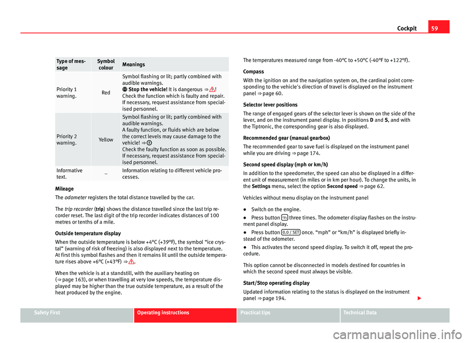
Cockpit Type of mes-
sag
e Symbol
co lour Meanings
Priority 1
warnin
g. Red Symbol flashing or lit; partly combined with
audibl
e w
arnings.
Stop the vehicle! It is dangerous ⇒ !
Check the f
unction which is faulty and repair.
If necessary, request assistance from special-
ised personnel. Priority 2
warnin
g. Yellow Symbol flashing or lit; partly combined with
audibl
e w
arnings.
A faulty function, or fluids which are below
the correct levels may cause damage to the
vehicle! ⇒ Check the faulty function as soon as possible.
If nec
e
ssary, request assistance from special-
ised personnel. Informative
te
xt
. – Information relating to different vehicle pro-
ce
s
ses. Mileage
The odometer
r
egisters the total distance travelled by the car.
The trip recorder (trip) shows the distance travelled since the last trip re- corder reset. The last digit of the trip recorder indicates distances of 100
metres or tenths of a mile.
Outside temperature display
When the outside temperature is below +4°C (+39°F), the symbol “ice crys-
tal” (warning of risk of freezing) is also displayed next to the temperature.
At first this symbol flashes and then it remains lit until the outside tempera-
ture rises above +6°C (+43°F) ⇒ .
When the v ehic
le is at a standstill, with the auxiliary heating on
(⇒ page 163), or when travelling at very low speeds, the temperature dis-
played may be higher than the true outside temperature, as a result of the
heat produced by the engine. The temperatures measured range from -40°C to +50°C (-40°F to +122°F).
Compa
ss
With the ignition on and the navigation system on, the cardinal point corre-
sponding to the vehicle's direction of travel is displayed on the instrument
panel ⇒ page 60.
Selector lever positions
The range of engaged gears of the selector lever is shown on the side of the
lever, and on the instrument panel display. In positions D and S, and with
the Tiptronic, the corresponding gear is also displayed.
Recommended gear (manual gearbox)
The recommended gear to save fuel is displayed on the instrument panel
while you are driving ⇒ page 174.
Second speed display (mph or km/h)
In addition to the speedometer, the speed can also be displayed in a differ-
ent unit of measurement (in miles or in km per hour). To change the units, in
the Settings menu, select the option Second speed ⇒ page 62.
Vehicles without menu display on the instrument panel
● Switch on the engine.
● Press button three times. The odometer display flashes on the instru-
ment p anel
display.
● Press button 0.0 / SET once. “mph” or “km/h” is displayed briefly in-
st e
ad of the odometer.
● This activates the second speed display. To switch it off, repeat the pro-
cedure.
Thi
s option cannot be disconnected in models destined for countries in
which the second speed must always be visible.
Start/Stop operating display
Updated information relating to the status is displayed on the instrument
panel ⇒ page 194. Safety First Operating instructions Practical tips Technical Data
Page 174 of 385
172
Driving
Key not authorised for the vehicle
If a k ey
which is not authorised for this vehicle is inserted in the ignition
lock, it can be removed as follows:
● Automatic gearbox: the key cannot be removed from the ignition lock.
Pres
s and release the selector lever locking button. Key can be removed
from the vehicle.
● Manual gearbox: Remove the key from the ignition. WARNING
Unsuitable or careless use of the vehicle key could result in serious in-
jury .
● A
lways take all the keys with you whenever you leave the vehicle. The
engine cou
ld accidentally be started and electrical equipment such as
the windows could accidentally be operated resulting in serious injury.
● Never leave children or disabled people alone in the car. They could
be trapped in the c
ar in an emergency and will not be able to get them-
selves to safety. For example, depending on the time of the year, temper-
atures inside a locked and closed vehicle can be extremely high or ex-
tremely low resulting in serious injuries and illness or even death, partic-
ularly for young children.
● Never remove the key from the ignition if the vehicle is in motion. The
steerin
g may lock and it will not be possible to turn the steering wheel. Note
● If the key is left in the ignition lock with the engine off for long periods,
the v
ehicle battery will run flat.
● For automatic gearbox vehicles the key
can only be removed from the ig-
nition lock if the gear selector lever is in position P. In this case, press and
release the selector lever locking button. Starting the engine Complete operations only in the sequence given:
Step
1. Press the brake pedal and keep pressed until step 5 has been
comp
l
eted. 1 a. In vehicles with a manual gearbox:
Pres
s the clutch pedal all
the way and keep pressed until the engine starts. 2. Put the gearstick in neutral or the selector lever in position
P
or N. 3. Only in vehicles with diesel engine:
To prehe
at, turn the key
in the ignition lock to position ⇒ fig. 127 1 . A warning lamp
lights up in the c ontr
ol panel . 4. Turn the key in the ignition lock to position
⇒ fig. 127 2 ; do
not pr e
ss the accelerator. 5. When the engine has started, release the key in the ignition
lock.
6. If the engine does not start, stop the process and try again af-
ter one minut
e. 7. Disconnect the electronic parking brake when you wish to
st
ar
t driving ⇒ page 183. WARNING
Never leave the vehicle unattended if the engine is running. The vehicle
cou l
d move off suddenly, especially if it is in gear, resulting in an acci-
dent and serious injury.
Page 175 of 385
173
Driving WARNING
Cold start sprays could explode or cause a sudden increase in the engine
speed.
● Nev er u
se start boosters. CAUTION
● An attempt to start the engine while driving or starting the engine imme-
di at
ely after turning it off can cause damage to the engine or starter motor.
● When the engine is cold, avoid high revs and heavy acceleration and do
not mak
e the engine work hard.
● Do not push or tow start the engine. Sunburnt fuel could damage the
catalytic
converter. For the sake of the environment
Do not warm the engine at idle speed; start driving immediately if the visi-
bi lity
is OK. This helps the engine reach operating temperature faster and
reduces emissions. Note
● For example, if the key battery is very worn or flat, the engine cannot be
s t
arted with the starter button. In this case, remove the ignition button from
the lock and insert the key.
● Electrical components with a high power consumption are switched off
temporari
ly when the engine starts.
● When the engine is started cold, there may be strong vibrations for a few
moments for t
echnical reasons. This is quite normal, and no cause for con-
cern.
● At temperatures below +5°C (+41°F), smoke may be given off below the
vehicl
e when the additional heater is connected. Stopping the engine Complete operations only in the sequence given:
Step
1. Stopping the vehicle completely
⇒ .
2. Press the brake pedal and keep pressed until step 4 has been
comp
l
eted. 3. In automatic gearboxes, put the selector lever in position
P. 4. Connect the electronic parking brake
⇒ page 183. 5. Turn the key in the ignition lock to position
⇒ fig. 127 0 .
6. With a manual gearbox, put the vehicle in first or reverse gear.
WARNING
Never switch off the engine while the vehicle is moving. You may lose
contr o
l of the vehicle and there is a risk of serious accident.
● The airbags and belt tensioners do not work when the ignition is
switc
hed off.
● The brake servo does not work when the engine is not running. To
stop
, the brake pedal must be pressed with more force.
● As the power steering does not work if the engine is not running, you
wil
l need more strength to steer than normally.
● If the key is removed from the ignition, the steering may lock and it
wil
l not be possible to steer the vehicle. CAUTION
If the engine has been driven at high speed for a prolonged period of time,
it m a
y overheat when turned off. To avoid engine damage, allow the engine
to run for approximately two minutes in neutral before switching it off. Safety First Operating instructions Practical tips Technical Data
Page 176 of 385
174
Driving Note
● In vehicles with automatic gearbox, the key can only be removed when
the sel ect
or lever is in position P.
● After stopping the engine, the engine compartment fan may continue
running f
or a few minutes, even when the ignition has been switched off or
the key removed. The radiator fan is automatically switched off.
Electronic immobiliser The gear lock prevents the engine from being started with an unauthorised
key
and the
vehicle being moved.
The vehicle key has a built-in chip. It automatically deactivates the immobil-
izer when the key is inserted into the ignition lock.
For this reason, the vehicle can only be used with a genuine SEAT key with
the correct code. Coded keys can be obtained from your Authorised Service
Centre ⇒ page 71. If an unauthorised key is used, the message SAFE or Immobiliser active is
displayed on the instrument panel. The vehicle cannot be started in this
case Note
The correct operation of the vehicle is only guaranteed when original SEAT
key s
are used. Changing gear
Introduction When reverse gear is engaged and the ignition is switched on the following
tak
e
s place:
● Reverse lights light up.
● When reversing, the air conditioner automatically changes to air recircu-
lation mode.
● The re
ar window heater switches on when the windscreen wiper is acti-
vated.
● A
lso, the parking sensor system, the optical parking sensor and the
camera f
or the reverse assist system are connected.
Additional information and warnings:
● Instruments ⇒ page 57
● Br
aking, stopping and parking ⇒ page 183
● P
arking sensor system ⇒ page 198
● P
ark Assist system ⇒ page 202
● R
everse assist system (Rear Assist) ⇒ page 207
● Air c
onditioning ⇒ page 155
● El
ectronic power control and exhaust gases purification system
⇒ page 228
● Emer
gency locking and unlocking ⇒ page 314 WARNING
Rapid acceleration can cause loss of traction and skidding, especially on
slip per
y ground. This could cause loss of control of the vehicle resulting
in an accident and considerable damage.
● Only use the kickdown or rapid acceleration if visibility, weather, road
and traffic c
onditions so permit.
Page 178 of 385
176
Driving
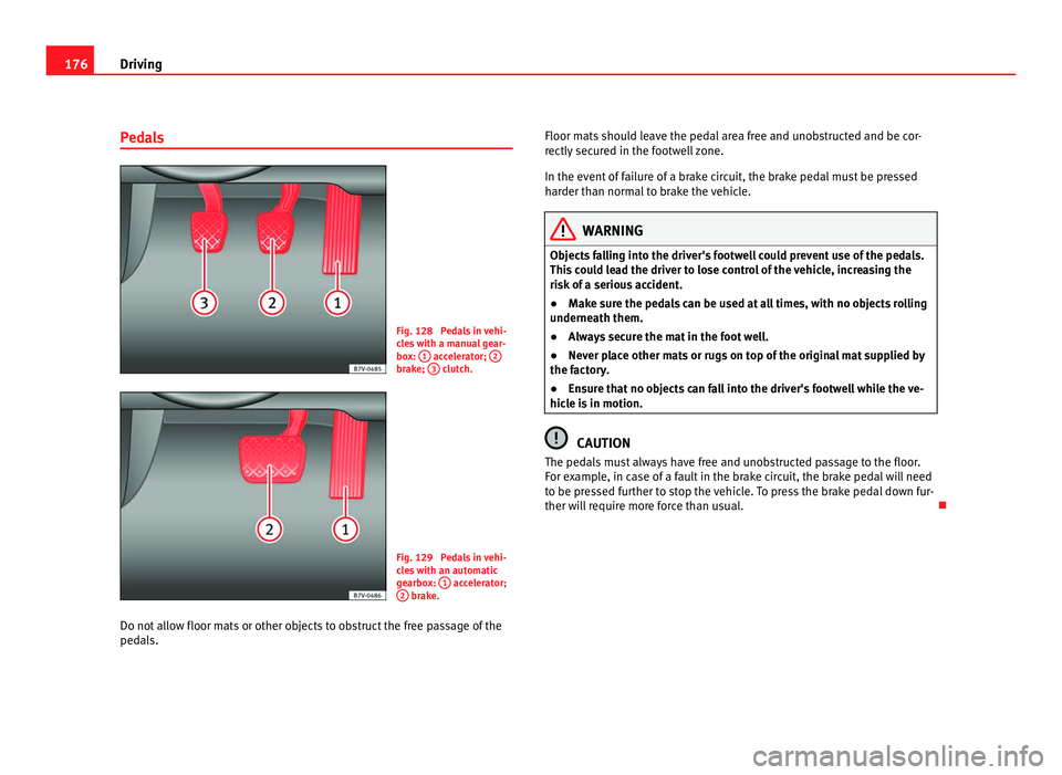
Pedals Fig. 128 Pedals in vehi-
cl
e
s with a manual gear-
box: 1 accelerator;
2 brake;
3 clutch.
Fig. 129 Pedals in vehi-
cl
e
s with an automatic
gearbox: 1 accelerator;
2 brake.
Do not allow floor mats or other objects to obstruct the free passage of the
pedal s. Floor m
ats should leave the pedal area free and unobstructed and be cor-
rectly sec
ured in the footwell zone.
In the event of failure of a brake circuit, the brake pedal must be pressed
harder than normal to brake the vehicle. WARNING
Objects falling into the driver's footwell could prevent use of the pedals.
This c
ould lead the driver to lose control of the vehicle, increasing the
risk of a serious accident.
● Make sure the pedals can be used at all times, with no objects rolling
underneath them.
● A
lways secure the mat in the foot well.
● Never place other mats or rugs on top of the original mat supplied by
the factor
y.
● Ensure that no objects can fall into the driver's footwell while the ve-
hicle i
s in motion. CAUTION
The pedals must always have free and unobstructed passage to the floor.
For e x
ample, in case of a fault in the brake circuit, the brake pedal will need
to be pressed further to stop the vehicle. To press the brake pedal down fur-
ther will require more force than usual.
Page 179 of 385
177
Driving
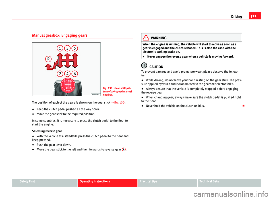
Manual gearbox: Engaging gears Fig. 130 Gear shift pat-
tern of
a 6-
speed manual
gearbox.
The position of each of the gears is shown on the gear stick ⇒ fig. 130.
● Keep the clutch pedal pushed all the way down.
● Move the gear stick to the required position.
In some countrie
s, it is necessary to press the clutch pedal to the floor to
start the engine.
Selecting reverse gear
● With the vehicle at a standstill, press the clutch pedal to the floor and
keep pre
ssed.
● Push the gear lever down.
● Move the gear stick to the left and then forwards to reverse gear R . WARNING
When the engine is running, the vehicle will start to move as soon as a
ge ar i
s engaged and the clutch released. This is also the case with the
electronic parking brake on.
● Never engage the reverse gear when a vehicle is moving forward. CAUTION
To prevent damage and avoid premature wear, please observe the follow-
ing:
● Whi l
e driving, do not leave your hand resting on the gear stick. The pres-
sure ap
plied by your hand is transmitted to the gearbox selector forks.
● Always ensure that the vehicle is completely stopped before engaging
the rever
se gear.
● When changing gear, always make sure the clutch pedal is pushed right
to the floor.
● Nev
er hold the vehicle on the clutch on hills. Safety First Operating instructions Practical tips Technical Data
Page 180 of 385
178
Driving
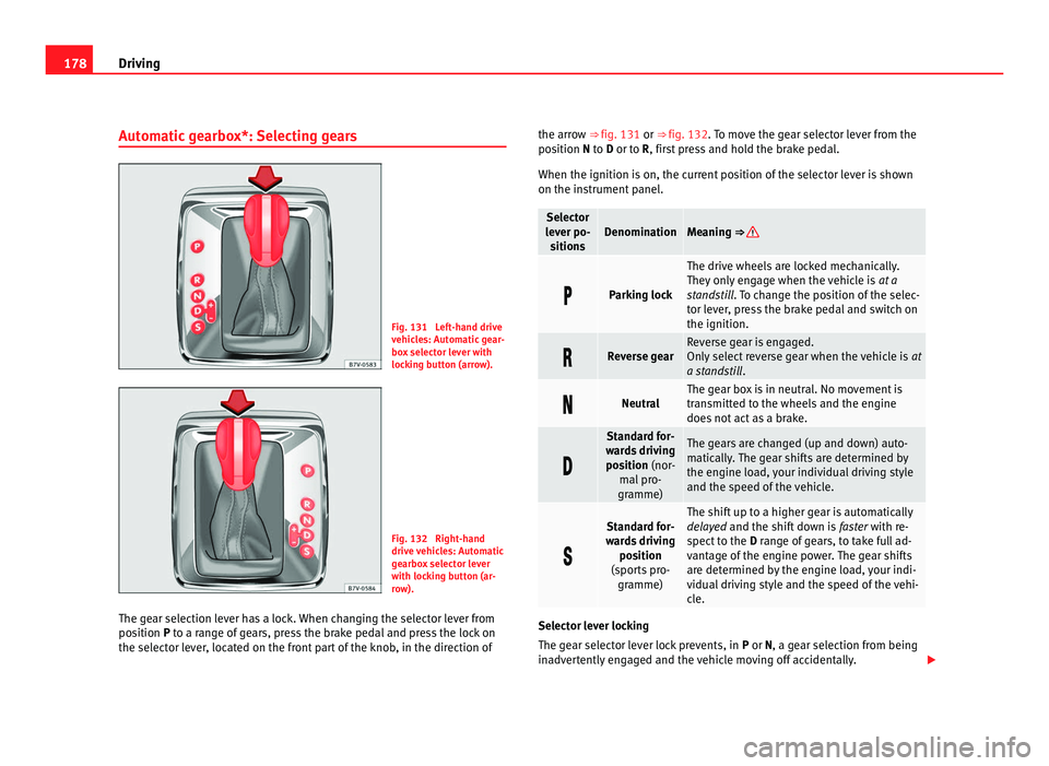
Automatic gearbox*: Selecting gears Fig. 131 Left-hand drive
vehic
l
es: Automatic gear-
box selector lever with
locking button (arrow). Fig. 132 Right-hand
drive
v
ehicles: Automatic
gearbox selector lever
with locking button (ar-
row).
The gear selection lever has a lock. When changing the selector lever from
position
P to a range of gears, press the brake pedal and press the lock on
the selector lever, located on the front part of the knob, in the direction of the arrow ⇒ fig. 131 or ⇒
fig. 132.
To move the gear selector lever from the
position N to D or to R, first press and hold the brake pedal.
When the ignition is on, the current position of the selector lever is shown
on the instrument panel. Selector
lev er po-
s
itions Denomination Meaning ⇒
Parking lock The drive wheels are locked mechanically.
They on
ly
engage when the vehicle is at a
standstill. To change the position of the selec-
tor lever, press the brake pedal and switch on
the ignition. Reverse gear Reverse gear is engaged.
Only
sel
ect reverse gear when the vehicle is at
a standstill . Neutral The gear box is in neutral. No movement is
tran
smitt
ed to the wheels and the engine
does not act as a brake. Standard for-
war d
s driving
position (nor- mal pro-
gramme) The gears are changed (up and down) auto-
matic
al
ly. The gear shifts are determined by
the engine load, your individual driving style
and the speed of the vehicle. Standard for-
war d
s driving
position
(sports pro- gramme) The shift up to a higher gear is automatically
dela
y
ed and the shift down is faster with re-
spect to the D range of gears, to take full ad-
vantage of the engine power. The gear shifts
are determined by the engine load, your indi-
vidual driving style and the speed of the vehi-
cle. Selector lever locking
The ge
ar sel
ector lever lock prevents, in P or N, a gear selection from being
inadvertently engaged and the vehicle moving off accidentally.