service Seat Alhambra 2014 Owner's Guide
[x] Cancel search | Manufacturer: SEAT, Model Year: 2014, Model line: Alhambra, Model: Seat Alhambra 2014Pages: 381, PDF Size: 5.75 MB
Page 103 of 381
101
Lights and visibility
● If the windscreen is damaged by the impact from a stone in the camera's
field of vision
● If the camera's field of vision is misted up, dirty or covered by a sticker,
snow or ice.
WARNING
The greater comfort that the headlight adjustment provides (automatic
also) must not cause you to take risks. The system is not a replacement
for driver awareness.
● Always monitor the lights yourself and adjust them depending on the
light, visibility and traffic conditions.
● The headlight adjustment (automatic also) may not correctly detect
all situations and in certain situations may only provide limited function.
● If the windscreen is damaged or modifications are made to the vehi-
cle lighting, this may harm the functioning of the headlight adjustment
(automatic also), for example, if additional headlight are fitted.
Note
Main beam and flashed headlights can be turned on and off manually at
any time with the turn signal and main beam lever ⇒ page 97.
Adhesive strips for headlights or adjusting headlights
In those countries where vehicles drive on the other side of the road to the
home country, the asymmetric dipped beam may dazzle drivers of oncom-
ing vehicles. Therefore, when driving abroad, adhesive strips should be at-
tached to the headlights or the headlights should be adjusted accordingly.
The direction of the headlights can be adjusted from the instrument panel,
in the Tourist light submenu of the Configuration menu
⇒ page 67. For those vehicles in which it is not possible to adjust the headlights from
the menu, adhesive strips are used to cover certain parts of the headlamp
cover or the headlights may be adjusted at a specialised workshop. For fur-
ther information, please refer to a specialised workshop. SEAT recommends
visiting a Technical Service.
Note
Use of the Tourist light option and the adhesives on the headlights is only
allowed if they are to be used for a short period of time. To modify the direc-
tion of the headlights permanently, please take the vehicle to a specialised
workshop. SEAT recommends visiting a Technical Service.
“Coming home” and “Leaving home” function (orientation
lighting)
The “Coming home” function should be switched on manually. However the
“Leaving home” function is automatically controlled by a photo sensor.
“Coming home”Necessary operations
To switch sys-
tem on:
– Switch off the ignition.
– Briefly flash the headlights for approximately one sec-
ond ⇒ page 97.
The “Coming home” lighting comes on when the driver
door is opened. The delay in switching off the headlights
is counted from when the last door or rear lid is closed.
To switch sys-
tem off:
– Automatically at the end of the delay period.
– Automatically, if 30 seconds after coming on, a vehicle
door or tailgate remains open.
– If the light switch is turned to position .
– If the ignition is switched on.
Safety FirstOperating instructionsPractical TipsTechnical Specifications
Page 108 of 381
106Lights and visibility
Windscreen wiper and washer
Introduction
Additional information and warnings:
● Recirculation of air conditioner air ⇒ page 157
● Working in the engine compartment ⇒ page 279
● Caring for and cleaning the vehicle exterior ⇒ page 246
WARNING
Water from the windscreen washer water bottle may freeze on the wind-
screen if it does not contain enough anti-freeze, reducing forward visibili-
ty.
● In winter, ensure the windscreen washer contains enough anti-freeze.
● In cold conditions, you should not use the wash/wipe system unless
you have warmed the windscreen with the ventilation system. The anti-
freeze could freeze on the windscreen and reduce visibility.
WARNING
Worn or dirty wiper blades reduce visibility and increase the risk of acci-
dent and serious injury.
● Always replace damaged or worn blades or blades which do not clean
the windscreen correctly.
CAUTION
In icy conditions, always check that the wiper blades are not frozen to the
glass before using the wipers for the first time. In cold weather, it may help
to leave the vehicle parked with the wipers in service position ⇒ page 108. Control lamp
lights upPossible causeSolution
Windscreen wiper fluid level
too lowTop up the windscreen wiper
reservoir as soon as possible
⇒ page 110.
Several warning and control lamps should light up for a few seconds when
the ignition is switched on, signalling that the function is being verified.
They will switch off after a few seconds.
CAUTION
Failure to heed the control lamps and text messages when they appear may
result in faults in the vehicle.
Page 110 of 381
108Lights and visibility
Windscreen wiper functions
Windscreen wiper performance in different situations:If the vehicle is at a stand-
still:The activated position provisionally changes
to the previous position.
During the automatic wipe:
The air conditioner comes on for approxi-
mately 30 seconds in air recirculation mode
to prevent the smell of the windscreen wash-
er fluid entering the inside the vehicle.
For the interval wipe:The intervals between wipes vary according
to the speed of the vehicle. The higher the
vehicle speed the shorter the intervals.
Heated windscreen washer jets
The heating only thaws the frozen jets, it does not thaw the water in the
washer hoses. The heated windscreen washer jets automatically adjust the
heat depending on the ambient temperature, when the ignition is switched
on.
Headlight wash/wipe system
The headlight washers/wipers clean the headlight lenses.
After the ignition is switched on, the first and every fifth time the wind-
screen washer is switched on, the headlights are also washed. Therefore,
the windscreen wiper lever should be pulled towards the steering wheel
when the dipped beam or main beam are on. Any incrusted dirt (such as in-
sects) should be cleaned regularly (e.g. when refuelling).
To ensure the headlight washers work correctly in winter, any snow which
has got into the bumper jet supports should be cleaned away. If necessary,
remove snow with an anti-icing spray.
Note
The wiper will try to wipe away any obstacles that are on the windscreen.
The wiper will stop moving if the obstacle blocks its path. Remove the ob-
stacle and switch the wiper back on again.
Windscreen wipers service position
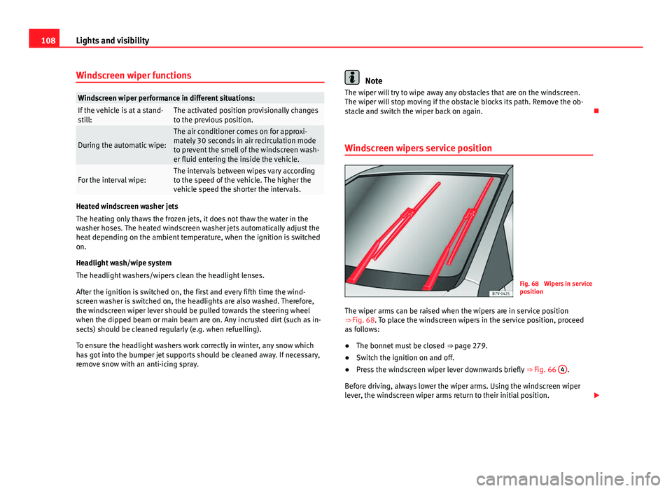
Fig. 68 Wipers in service
position
The wiper arms can be raised when the wipers are in service position
⇒ Fig. 68. To place the windscreen wipers in the service position, proceed
as follows:
● The bonnet must be closed ⇒ page 279.
● Switch the ignition on and off.
● Press the windscreen wiper lever downwards briefly ⇒ Fig. 66 4
.
Before driving, always lower the wiper arms. Using the windscreen wiper
lever, the windscreen wiper arms return to their initial position.
Page 111 of 381
109
Lights and visibility
Lifting and returning windscreen wiper arms
● Place the wiper arms in the service position ⇒
.
● Only hold the wiper arms at the point where the blade is fixed.
CAUTION
● To prevent damage to the bonnet and the wiper arms, only leave them in
the service position.
● Before driving, always lower the wiper arms.
Rain sensor*
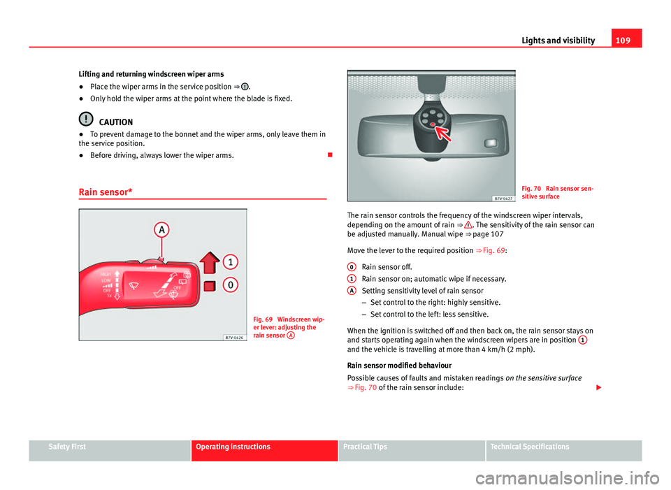
Fig. 69 Windscreen wip-
er lever: adjusting the
rain sensor A
Fig. 70 Rain sensor sen-
sitive surface
The rain sensor controls the frequency of the windscreen wiper intervals,
depending on the amount of rain ⇒
. The sensitivity of the rain sensor can
be adjusted manually. Manual wipe ⇒ page 107
Move the lever to the required position ⇒ Fig. 69:
Rain sensor off.
Rain sensor on; automatic wipe if necessary.
Setting sensitivity level of rain sensor
– Set control to the right: highly sensitive.
– Set control to the left: less sensitive.
When the ignition is switched off and then back on, the rain sensor stays on
and starts operating again when the windscreen wipers are in position 1
and the vehicle is travelling at more than 4 km/h (2 mph).
Rain sensor modified behaviour
Possible causes of faults and mistaken readings
on the sensitive surface
⇒ Fig. 70 of the rain sensor include:
0
1A
Safety FirstOperating instructionsPractical TipsTechnical Specifications
Page 113 of 381

111
Lights and visibility
WARNING
Never mix an unsuitable antifreeze or other similar additives with the
windscreen washer water. A greasy layer may be formed on the wind-
screen which will impair visibility.
● Use clean water with a window cleaner recommended by SEAT.
● If necessary, add a suitable antifreeze to the water in the reservoir.
CAUTION
● Do not mix cleaning products recommended by SEAT with other prod-
ucts. This could lead to flocculation and may block the windscreen washer
jets.
● When topping up service fluids, make absolutely certain that you fill the
fluids into the correct reservoirs. Using the wrong fluids could cause serious
malfunctions and engine damage!
Rear vision mirror
Introduction
Additional information and warnings:
● Personal convenience settings in the SEAT information system
⇒ page 62
● Seat memory
⇒ page 118
● Changing gear
⇒ page 176
● Braking, stopping and parking
⇒ page 185
WARNING
The automatic anti-dazzle rear vision mirror contains an electrolytic fluid
which may leak if the mirror is broken. This could cause irritation to the
skin, eyes and respiratory organs.
● The electrolytic fluid may cause irritation to the skin, eyes and respi-
ratory organs, particularly in individuals suffering from asthma or other
illnesses. Make sure that adequate quantities of fresh air enter and leave
the vehicle if it is not possible to open all the doors and windows.
● If the electrolytic fluid comes into contact with eyes or skin, wash the
area for at least 15 minutes with plenty of water, and seek medical ad-
vice.
● If the electrolytic fluid comes into contact with shoes or clothing,
wash the area for at least 15 minutes with plenty of water. Wash shoes
and clothing before wearing them again.
● If the electrolytic fluid is swallowed, wash your mouth with plenty of
water for at least 15 minutes. Do not try to provoke vomiting unless rec-
ommended by a Doctor. Seek medical advice immediately.
CAUTION
In the event that an automatic anti-dazzle rear vision mirror breaks, an elec-
trolyte fluid may leak. This liquid attacks plastic surfaces. Therefore, it
should be cleaned as fast as possible with a damp sponge or similar.
Safety FirstOperating instructionsPractical TipsTechnical Specifications
Page 138 of 381
136Seats and storage
WARNING (Continued)
● Loose objects in the luggage compartment can suddenly slide and
change the way the vehicle handles.
● Secure all objects, little and large.
● Never secure a load that is too heavy for the fastening rings.
● Never secure a child seat to the fastening rings.
Note
● The maximum load of the fastening rings is approximately 3.5 Kn (3.57
Kp).
● You can find suitable transport straps and load securing systems at a
specialised workshop. SEAT recommends visiting a Technical Service.
Rails and attachment system*
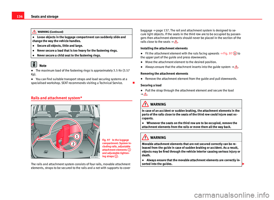
Fig. 97 In the luggage
compartment: System in-
cluding rails, adjustable
attachment elements 1
and adjustable tighten-
ing straps 2.
The rails and attachment system consists of four rails, movable attachment
elements, straps to be secured to the rails and a net with supports to cover baggage ⇒ page 137. The rail and attachment system is designed to se-
cure light objects. If the seats in the third row are to be occupied by passen-
gers then attachment elements should never be placed in the section of the
rails close to the seats
⇒
.
Installing the attachment elements
● Fit the attachment element with the ruts facing upwards ⇒ Fig. 97 1
to
the upper part of the guide and press downwards.
● Move the attachment element to the desired position.
● Always ensure that the attachment inserts into the guide system ⇒
.
Removing the attachment elements
● Remove the attachment element from the guide and pull downwards.
Securing a load
● Pull the strap through the attachment element and secure the load
⇒
.
WARNING
In case of an accident or sudden braking, the attachment elements in the
parts of the rails close to the seats of the third row could injure seat oc-
cupants.
● Whenever the seats on the third row are to be occupied, remove the
attachment elements from the rails or move them all the way back.
WARNING
Movable attachment elements that are not secured correctly can be re-
leased from the guide in case of sudden braking or accident. As a result,
objects may be fired through the vehicle interior causing serious injury or
death.
● Always ensure that the movable attachment elements are correctly in-
serted into the guides.
Page 143 of 381
141
Seats and storage
CAUTION
● Always remove the roof carrier system from the roof before entering a car
wash.
● The height of your vehicle is changed by the installation of the roof carri-
er and the load secured on it. Compare the vehicle height with the passage
height, for example in underground car parks or entering garage doors.
● The roof antenna, the range of the panoramic sliding sunroof and the
rear lid should not be affected by the roof carrier system and the load being
transported.
● Take extra care not to let the rear lid strike the roof load when opening.
For the sake of the environment
The vehicle uses more fuel when the roof carrier system is fitted.
Securing the base supports and roof carrier system
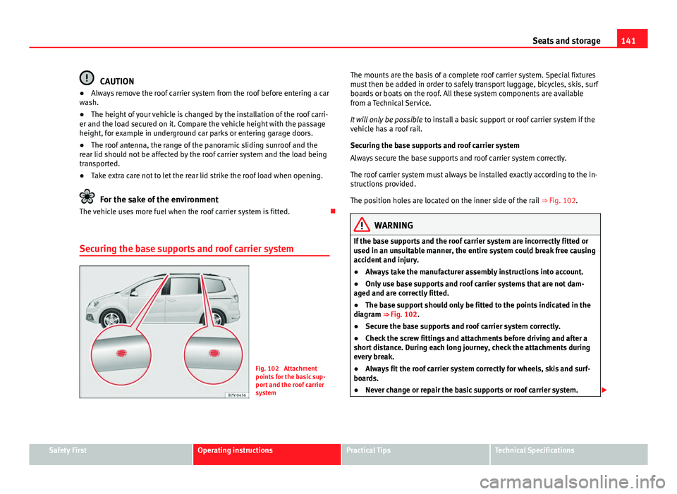
Fig. 102 Attachment
points for the basic sup-
port and the roof carrier
system The mounts are the basis of a complete roof carrier system. Special fixtures
must then be added in order to safely transport luggage, bicycles, skis, surf
boards or boats on the roof. All these system components are available
from a Technical Service.
It will only be possible
to install a basic support or roof carrier system if the
vehicle has a roof rail.
Securing the base supports and roof carrier system
Always secure the base supports and roof carrier system correctly.
The roof carrier system must always be installed exactly according to the in-
structions provided.
The position holes are located on the inner side of the rail ⇒ Fig. 102.
WARNING
If the base supports and the roof carrier system are incorrectly fitted or
used in an unsuitable manner, the entire system could break free causing
accident and injury.
● Always take the manufacturer assembly instructions into account.
● Only use base supports and roof carrier systems that are not dam-
aged and are correctly fitted.
● The base support should only be fitted to the points indicated in the
diagram ⇒ Fig. 102.
● Secure the base supports and roof carrier system correctly.
● Check the screw fittings and attachments before driving and after a
short distance. During each long journey, check the attachments during
every break.
● Always fit the roof carrier system correctly for wheels, skis and surf-
boards.
● Never change or repair the basic supports or roof carrier system.
Safety FirstOperating instructionsPractical TipsTechnical Specifications
Page 158 of 381
156Seats and storage
LED on the power socket ⇒ Fig. 122Steady green light:The childproof lock is unlocked. The power
socket can now be used.
Flashing red light:There is some kind of fault (e.g. discon-
nection due to excess current or tempera-
ture).
Heat protection
The 230 Volt Euro power connector converter switches off automatically
when a certain temperature is exceeded. This disconnect prevents overheat-
ing in the event of an increase in power consumption of the connected ap-
pliance and where the atmospheric temperature is too high. The inverter
will switch on again automatically after it has cooled down. Appliances that
are switched on and connected to the power socket will start up again.
Therefore, switch off all electrical appliances connected to the power socket
when the current converter switches off due to overheating.
WARNING
High voltage in the electrical installation!
● Liquids must not be spilt over the power socket.
● Do not plug adapters or extension cords into the 230 Volt Euro power
connector. Otherwise, the built-in child safety device will switch off and
the connector will become live.
● Do not plug current conductors such as a knitting needle into the 230
Volt Euro power connector.
CAUTION
● Always follow the operating instructions for the appliances to be con-
nected!
● Never exceed the maximum power rating as this could damage the vehi-
cle's general electrical system. ●
12 volt power socket:
– Only use accessories with approved electromagnetic compatibility ac-
cording to current regulations.
– Never power the socket.
● 230 Volt Euro power socket:
– Do not hang appliances or plugs that are too heavy (e.g. a transform-
er) from the power socket.
– Do not connect lamps which contain a neon tube.
– Only plug appliances with a voltage that matches the power socket
voltage into the power socket.
– In the event of consumers with a high start-up current, surge protec-
tion prevents them from switching on. In this case, unplug the consumer
and try plugging it back in after around 10 seconds.
Note
● Some appliances may not work properly in the 230 Volt Euro power con-
nector due to a lack of power (Watts).
● The 230 Watt Euro power connector can be modified for 115 Watt appli-
ances and vice versa. Consult a specialist shop for advice on accessories to
adapt the connector. SEAT recommends visiting a Technical Service.
Page 159 of 381
157
Air conditioning
Air conditioning Air conditioner
Introduction
Viewing Climatronic information
The factory-fitted radio or navigation system screen briefly displays informa-
tion relating to Climatronic.
The units of temperature measurement is displayed on the factory-installed
radio or navigation system and, depending on the vehicle equipment, can
be set using the Configuration menu on the instrument panel.
Additional information and warnings:
● SEAT information system ⇒ page 62
● Windscreen wash system ⇒ page 106
● Auxiliary heating ⇒ page 165
● Caring for and cleaning the vehicle exterior ⇒ page 246
WARNING
Reduced visibility through the windows increases the risk of serious acci-
dents.
● Ensure that all windows are free of ice and snow and that they are not
fogged up preventing a clear view of everything outside.
● The maximum heat output required to defrost windows quickly is only
available when the engine has reached its normal running temperature.
Only drive when you have good visibility.
WARNING (Continued)
● Always ensure that you use the air conditioner and heated rear win-
dow to maintain good visibility.
● Never leave the air recirculation on for a long period of time. If the
cooling system is switched off and air recirculation mode switched on,
the windows can mist over very quickly, considerably limiting visibility.
● Switch air recirculation mode off when it is not required.
WARNING
Stuffy or used air will increase fatigue and reduce driver concentration
possibly resulting in a serious accident.
● Never leave the fresh air fan turned off or use the air recirculation for
long periods of time; the air in the vehicle interior will not be refreshed.
CAUTION
● Switch the air conditioner off if you think it may be broken. This will
avoid additional damage. Have the air conditioner checked by a specialised
workshop.
● Repairs to the air conditioner require specialist knowledge and special
tools. SEAT recommends visiting a Technical Service.
● Do not smoke when air recirculation is switched on in vehicles with an
air conditioner. The smoke taken in could lie on the cooling system vaporis-
er and on the activated charcoal cartridge of the dust and pollen filter, lead-
ing to a permanently unpleasant smell.
Safety FirstOperating instructionsPractical TipsTechnical Specifications
Page 178 of 381
176Driving
Note
● In vehicles with automatic gearbox, the key can only be removed when
the selector lever is in position P.
● After stopping the engine, the engine compartment fan may continue
running for a few minutes, even when the ignition has been switched off or
the key removed. The radiator fan is automatically switched off.
Electronic immobiliser
The gear lock prevents the engine from being started with an unauthorised
key and the vehicle being moved.
The vehicle key has a built-in chip. It automatically deactivates the electron-
ic immobiliser when the key is inserted into the ignition lock.
For this reason, the vehicle can only be used with a genuine SEAT key with
the correct code. Coded keys can be obtained from your Technical Services
⇒ page 72.
If an unauthorised key is used, the message SAFE or Immobiliser active is
displayed on the instrument panel. The vehicle cannot be started in this
case
Note
The correct operation of the vehicle is only guaranteed when original SEAT
keys are used. Changing gear
Introduction
When reverse gear is engaged and the ignition is switched on the following
takes place:
● Reverse lights light up.
● When reversing, the air conditioner automatically changes to air recircu-
lation mode.
● The rear window heater switches on when the windscreen wiper is acti-
vated.
● Also, the parking sensor system, the optical parking sensor and the
camera for the reverse assist system are connected.
Additional information and warnings:
● Instruments ⇒ page 57
● Braking, stopping and parking ⇒ page 185
● Parking sensor system ⇒ page 200
● Park Assist system ⇒ page 204
● Reverse assist system (Rear Assist) ⇒ page 209
● Air conditioning ⇒ page 157
● Electronic power control and exhaust gases purification system
⇒ page 232
● Emergency locking and unlocking ⇒ page 318
WARNING
Rapid acceleration can cause loss of traction and skidding, especially on
slippery ground. This could cause loss of control of the vehicle resulting
in an accident and considerable damage.
● Only use the kick-down function or rapid acceleration if visibility,
weather, road and traffic conditions so permit.