Seat Alhambra 2014 Owner's Manual
Manufacturer: SEAT, Model Year: 2014, Model line: Alhambra, Model: Seat Alhambra 2014Pages: 381, PDF Size: 5.75 MB
Page 321 of 381
319
If and when
WARNING
Opening and closing doors carelessly can cause serious injury.
● If the vehicle is locked from outside, the doors and windows cannot
be opened from the inside.
● Never leave children or disabled people alone in the car. They could
be trapped in the car in an emergency and will not be able to get them-
selves to safety.
● Depending on the time of the year, temperatures inside a locked and
closed vehicle can be extremely high or extremely low resulting in seri-
ous injuries and illness or even death, particularly for young children.
WARNING
Getting in the way of the doors and the panoramic sliding sunroof is dan-
gerous and can lead to serious injury.
● Open and close the doors and the panoramic sliding sunroof only
when nobody is in the way.
CAUTION
When opening and closing in an emergency, carefully disassemble compo-
nents and then reassemble them carefully to avoid damage to the vehicle. Manually locking and unlocking the driver door
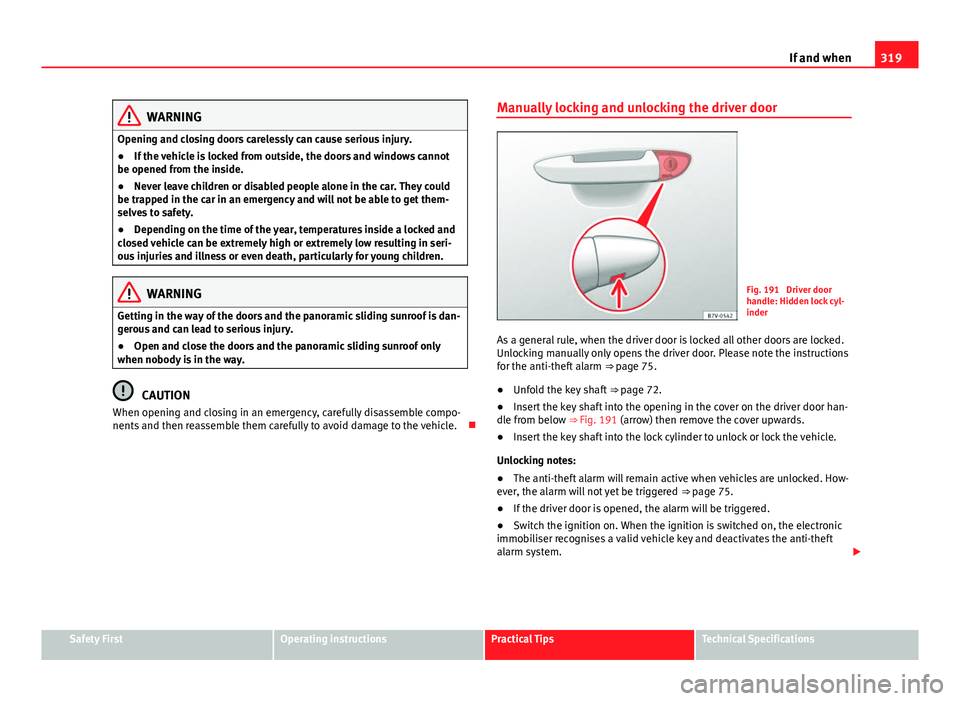
Fig. 191 Driver door
handle: Hidden lock cyl-
inder
As a general rule, when the driver door is locked all other doors are locked.
Unlocking manually only opens the driver door. Please note the instructions
for the anti-theft alarm ⇒ page 75.
● Unfold the key shaft
⇒ page 72.
● Insert the key shaft into the opening in the cover on the driver door han-
dle from below ⇒ Fig. 191 (arrow) then remove the cover upwards.
● Insert the key shaft into the lock cylinder to unlock or lock the vehicle.
Unlocking notes:
● The anti-theft alarm will remain active when vehicles are unlocked. How-
ever, the alarm will not yet be triggered ⇒ page 75.
● If the driver door is opened, the alarm will be triggered.
● Switch the ignition on. When the ignition is switched on, the electronic
immobiliser recognises a valid vehicle key and deactivates the anti-theft
alarm system.
Safety FirstOperating instructionsPractical TipsTechnical Specifications
Page 322 of 381
320If and when
Note
The anti-theft alarm is not activated when the vehicle is locked manually us-
ing the key ⇒ page 75.
Locking the passenger side door and sliding doors
manually
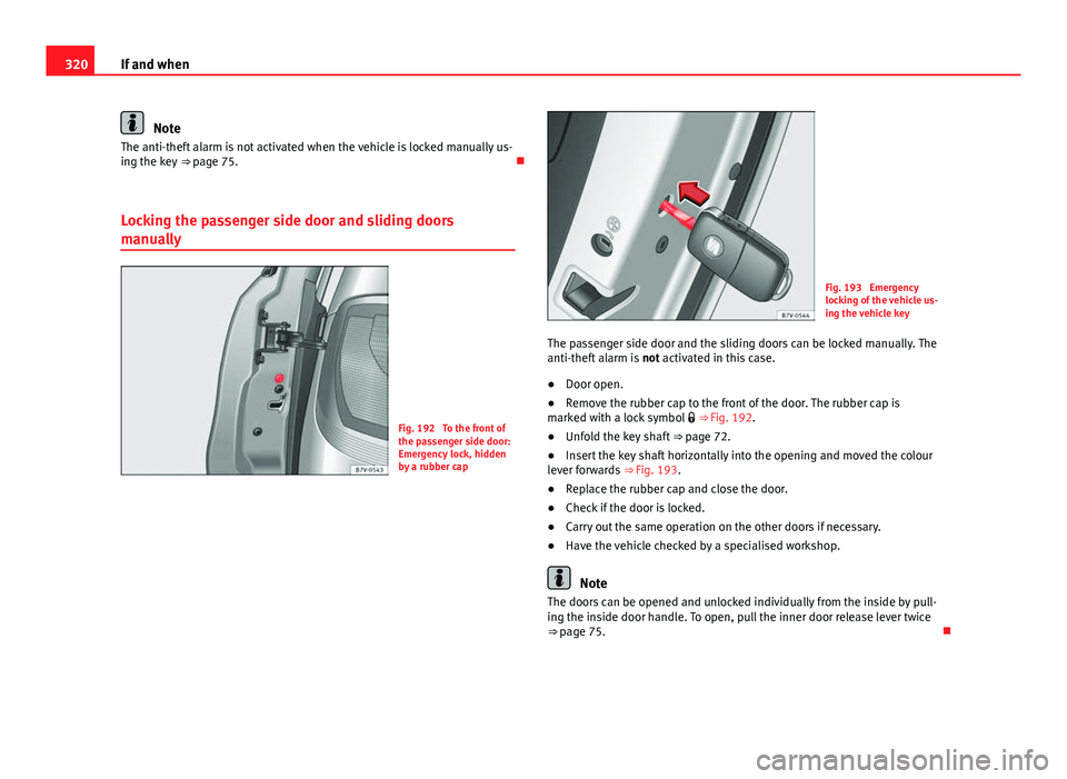
Fig. 192 To the front of
the passenger side door:
Emergency lock, hidden
by a rubber cap
Fig. 193 Emergency
locking of the vehicle us-
ing the vehicle key
The passenger side door and the sliding doors can be locked manually. The
anti-theft alarm is not activated in this case.
● Door open.
● Remove the rubber cap to the front of the door. The rubber cap is
marked with a lock symbol ⇒ Fig. 192.
● Unfold the key shaft ⇒ page 72.
● Insert the key shaft horizontally into the opening and moved the colour
lever forwards ⇒ Fig. 193.
● Replace the rubber cap and close the door.
● Check if the door is locked.
● Carry out the same operation on the other doors if necessary.
● Have the vehicle checked by a specialised workshop.
Note
The doors can be opened and unlocked individually from the inside by pull-
ing the inside door handle. To open, pull the inner door release lever twice
⇒ page 75.
Page 323 of 381
321
If and when
Emergency unlocking the rear lid
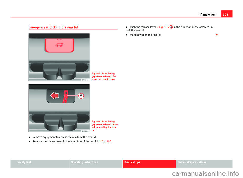
Fig. 194 From the lug-
gage compartment: Re-
move the rear lid cover
Fig. 195 From the lug-
gage compartment: Man-
ually unlocking the rear
lid
● Remove equipment to access the inside of the rear lid.
● Remove the square cover in the inner trim of the rear lid ⇒ Fig. 194.●
Push the release lever ⇒ Fig. 195 A
in the direction of the arrow to un-
lock the rear lid.
● Manually open the rear lid.
Safety FirstOperating instructionsPractical TipsTechnical Specifications
Page 324 of 381
322If and when
Manually closing the panoramic sliding sunroof
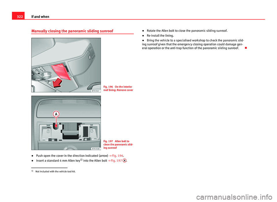
Fig. 196 On the interior
roof lining: Remove cover
Fig. 197 Allen bolt to
close the panoramic slid-
ing sunroof
● Push open the cover in the direction indicated (arrow) ⇒ Fig. 196.
● Insert a standard 4 mm Allen key 1)
into the Allen bolt ⇒ Fig. 197 A
. ●
Rotate the Allen bolt to close the panoramic sliding sunroof.
● Re-install the lining.
● Bring the vehicle to a specialised workshop to check the panoramic slid-
ing sunroof given that the emergency closing operation could damage gen-
eral operation or the anti-trap function of the panoramic sliding sunroof.
1)
Not included with the vehicle tool kit.
Page 325 of 381
323
If and when
Manually unlocking the gear selector lever
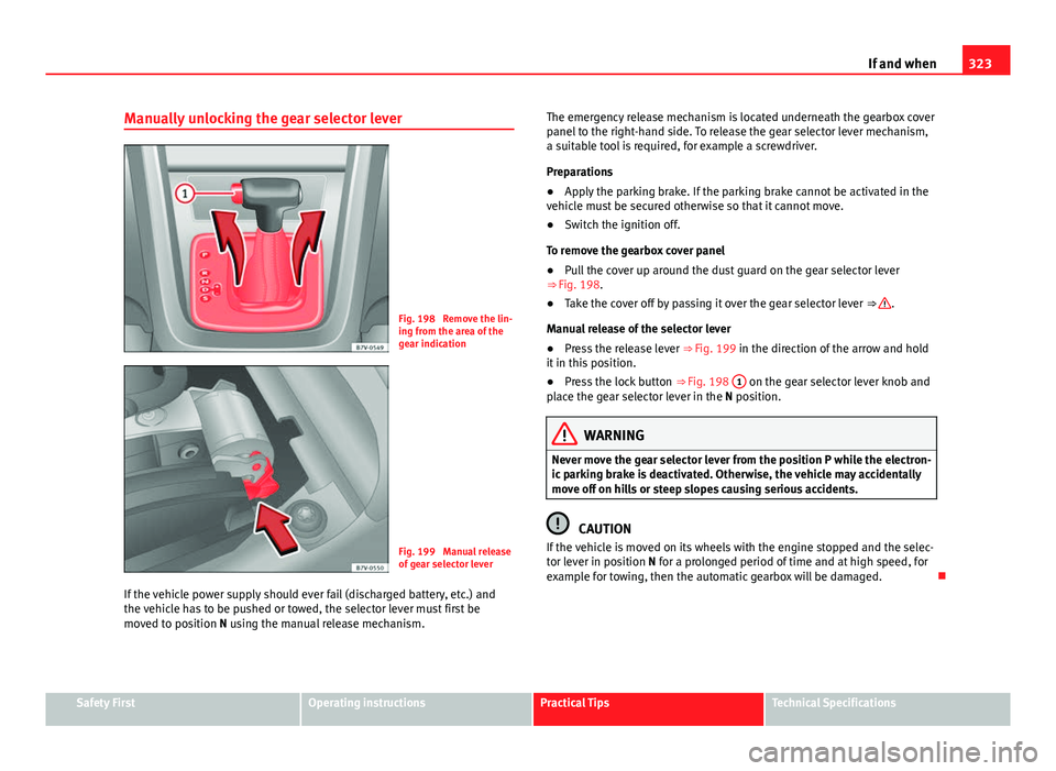
Fig. 198 Remove the lin-
ing from the area of the
gear indication
Fig. 199 Manual release
of gear selector lever
If the vehicle power supply should ever fail (discharged battery, etc.) and
the vehicle has to be pushed or towed, the selector lever must first be
moved to position N using the manual release mechanism. The emergency release mechanism is located underneath the gearbox cover
panel to the right-hand side. To release the gear selector lever mechanism,
a suitable tool is required, for example a screwdriver.
Preparations
●
Apply the parking brake. If the parking brake cannot be activated in the
vehicle must be secured otherwise so that it cannot move.
● Switch the ignition off.
To remove the gearbox cover panel
● Pull the cover up around the dust guard on the gear selector lever
⇒ Fig. 198.
● Take the cover off by passing it over the gear selector lever ⇒
.
Manual release of the selector lever
● Press the release lever ⇒ Fig. 199 in the direction of the arrow and hold
it in this position.
● Press the lock button ⇒ Fig. 198 1
on the gear selector lever knob and
place the gear selector lever in the N position.
WARNING
Never move the gear selector lever from the position P while the electron-
ic parking brake is deactivated. Otherwise, the vehicle may accidentally
move off on hills or steep slopes causing serious accidents.
CAUTION
If the vehicle is moved on its wheels with the engine stopped and the selec-
tor lever in position N for a prolonged period of time and at high speed, for
example for towing, then the automatic gearbox will be damaged.
Safety FirstOperating instructionsPractical TipsTechnical Specifications
Page 326 of 381
324If and when
Vehicle tool kit*
Introduction
When securing the vehicle in case of a breakdown, please note the legal re-
quirements for each country.
Additional information and warnings:
● Working in the engine compartment ⇒ page 279
● Change wheel ⇒ page 310
● In case of emergency ⇒ page 316
WARNING
Loose objects in the vehicle interior can be violently fired through the
compartment in case of a sudden manoeuvre or braking and especially in
accidents causing serious injury.
● Make sure that the vehicle tools are stored safely in the luggage com-
partment.
WARNING
Unsuitable or damaged vehicle tools can cause injury or accidents.
● Never work with inappropriate or damaged tools.
Location
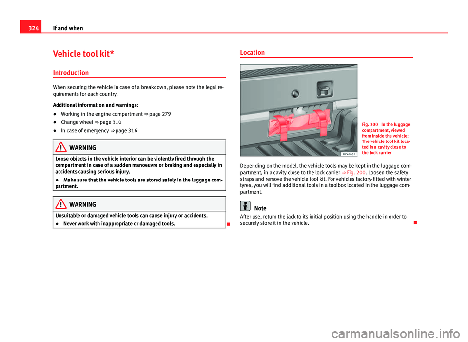
Fig. 200 In the luggage
compartment, viewed
from inside the vehicle:
The vehicle tool kit loca-
ted in a cavity close to
the lock carrier
Depending on the model, the vehicle tools may be kept in the luggage com-
partment, in a cavity close to the lock carrier ⇒ Fig. 200. Loosen the safety
straps and remove the vehicle tool kit. For vehicles factory-fitted with winter
tyres, you will find additional tools in a toolbox located in the luggage com-
partment.
Note
After use, return the jack to its initial position using the handle in order to
securely store it in the vehicle.
Page 327 of 381
325
If and when
Components
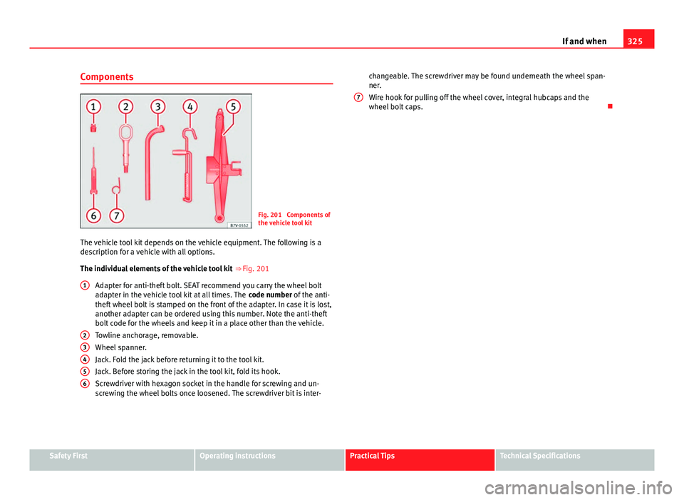
Fig. 201 Components of
the vehicle tool kit
The vehicle tool kit depends on the vehicle equipment. The following is a
description for a vehicle with all options.
The individual elements of the vehicle tool kit
⇒ Fig. 201
Adapter for anti-theft bolt. SEAT recommend you carry the wheel bolt
adapter in the vehicle tool kit at all times. The code number of the anti-
theft wheel bolt is stamped on the front of the adapter. In case it is lost,
another adapter can be ordered using this number. Note the anti-theft
bolt code for the wheels and keep it in a place other than the vehicle.
Towline anchorage, removable.
Wheel spanner.
Jack. Fold the jack before returning it to the tool kit.
Jack. Before storing the jack in the tool kit, fold its hook.
Screwdriver with hexagon socket in the handle for screwing and un-
screwing the wheel bolts once loosened. The screwdriver bit is inter-
1
23456
changeable. The screwdriver may be found underneath the wheel span-
ner.
Wire hook for pulling off the wheel cover, integral hubcaps and the
wheel bolt caps.
7
Safety FirstOperating instructionsPractical TipsTechnical Specifications
Page 328 of 381
326If and when
Fuses
Introduction
Due to the constant update of vehicles, fuse assignments depending on
equipment and the use of the same fuse for various electrical components,
at the time of printing this manual it is not possible to provide an up-to-date
summary of the electrical components fuse positions. For detailed informa-
tion about the fuse positions, please consult a Technical Service.
In general, a fuse can be assigned to various electrical components. Like-
wise, an electrical component can be protected by several fuses.
Only replace fuses when the cause of the problem has been solved. If a
newly inserted fuse blows after a short time, you must have the electrical
system checked by a specialised workshop as soon as possible.
Additional information and warnings:
● Working in the engine compartment ⇒ page 279
WARNING
The high voltages in the electrical system can give serious electrical
shocks, causing burns and even death!
● Never touch the electrical wiring of the ignition system.
● Take care not to cause short circuits in the electrical system.
WARNING
Using unsuitable fuses, repairing fuses or bridging a current circuit with-
out fuses can cause a fire and serious injury.
● Never use a fuse with a higher value. Only replace fuses with a fuse of
the same amperage (same colour and markings) and size.
● Never repair a fuse.
● Never replace a fuse by a metal strip, staple or similar.
CAUTION
● To avoid damage to the vehicles electric system, before replacing a fuse
turn off the ignition, the lights and all electrical elements and remove the
keys from the ignition.
● If you replace a fuse with higher-rating fuse, you could cause damage to
another part of the electrical system.
● Protect the fuse boxes when open to avoid the entry of dust or humidity.
Dirt and humidity inside fuse boxes can cause damage to the electrical sys-
tem.
Note
● One single consumer could have more than one fuse.
● Several consumers could run over one single fuse.
Page 329 of 381
327
If and when
Vehicle fuses
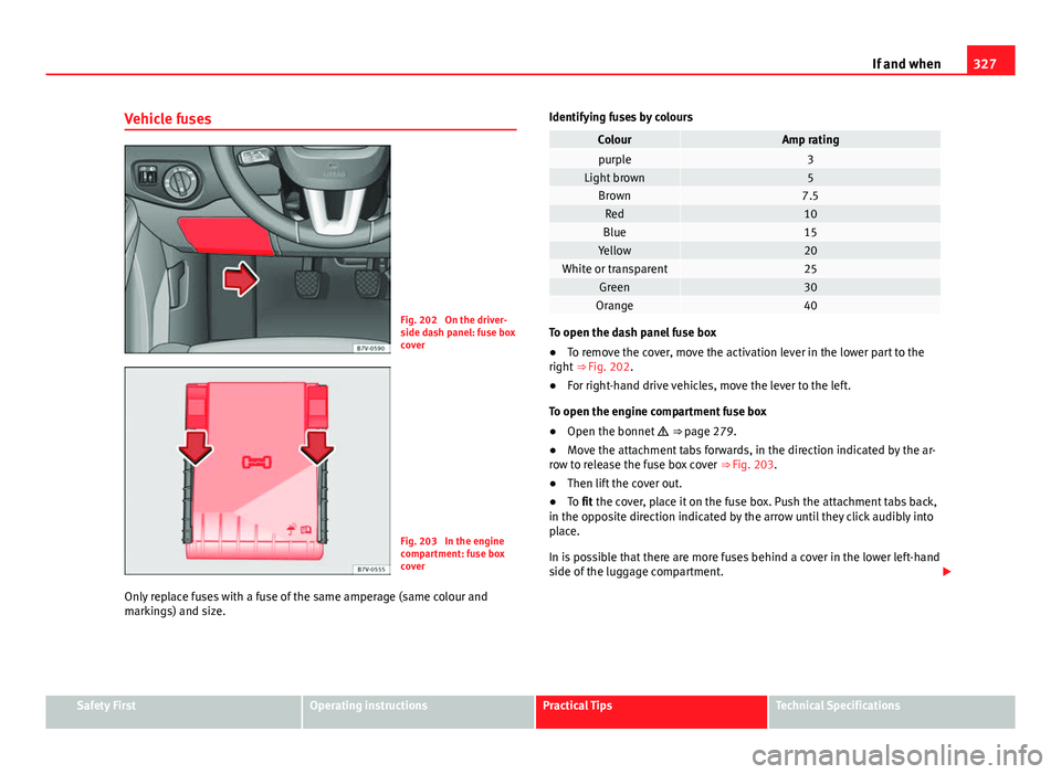
Fig. 202 On the driver-
side dash panel: fuse box
cover
Fig. 203 In the engine
compartment: fuse box
cover
Only replace fuses with a fuse of the same amperage (same colour and
markings) and size. Identifying fuses by colours
ColourAmp ratingpurple3Light brown5Brown7.5Red10Blue15Yellow20White or transparent25Green30Orange40
To open the dash panel fuse box
●
To remove the cover, move the activation lever in the lower part to the
right ⇒ Fig. 202.
● For right-hand drive vehicles, move the lever to the left.
To open the engine compartment fuse box
● Open the bonnet ⇒ page 279.
● Move the attachment tabs forwards, in the direction indicated by the ar-
row to release the fuse box cover ⇒ Fig. 203.
● Then lift the cover out.
● To fit the cover, place it on the fuse box. Push the attachment tabs back,
in the opposite direction indicated by the arrow until they click audibly into
place.
In is possible that there are more fuses behind a cover in the lower left-hand
side of the luggage compartment.
Safety FirstOperating instructionsPractical TipsTechnical Specifications
Page 330 of 381
328If and when
CAUTION
● Always carefully remove the fuse box covers and refit them correctly to
avoid problems with your vehicle.
● Protect the fuse boxes when open to avoid the entry of dust or humidity.
Dirt and humidity inside fuse boxes can cause damage to the electrical sys-
tem.
Note
In the vehicle, there are more fuses than those indicated in this chapter.
These should only be changed by a specialised workshop.
Replacing a blown fuse
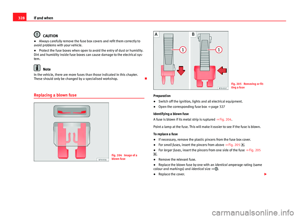
Fig. 204 Image of a
blown fuse
Fig. 205 Removing or fit-
ting a fuse
Preparation
● Switch off the ignition, lights and all electrical equipment.
● Open the corresponding fuse box
⇒ page 327
Identifying a blown fuse
A fuse is blown if its metal strip is ruptured ⇒ Fig. 204.
Point a lamp at the fuse. This will make it easier to see if the fuse is blown.
To replace a fuse
● If necessary, remove the plastic pincers from the fuse box cover.
● For small fuses, insert the pincers from above
⇒ Fig. 205 .
● For larger fuses , insert the pincers from one side of the fuse
⇒ Fig. 205
.
● Remove the relevant fuse.
● Replace the blown fuse by one with an identical amperage rating (same
colour and markings) and identical size ⇒
.
● Replace the cover.