headlights Seat Alhambra 2015 Owner's Manual
[x] Cancel search | Manufacturer: SEAT, Model Year: 2015, Model line: Alhambra, Model: Seat Alhambra 2015Pages: 305, PDF Size: 5.46 MB
Page 41 of 305
Cockpit
Operation
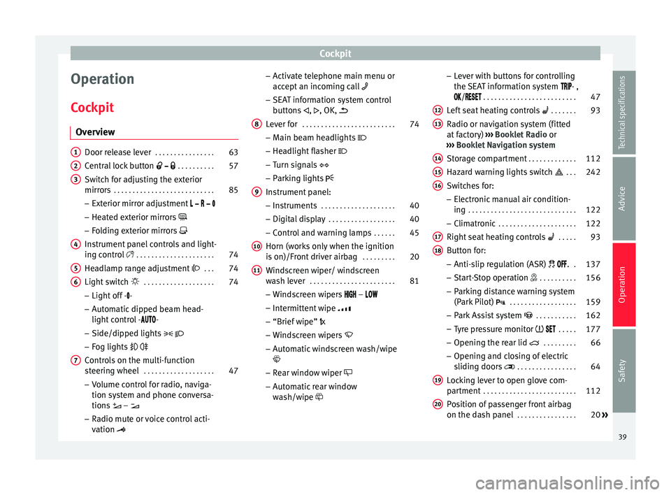
Cockpit Overview Door release lever
. . . . . . . . . . . . . . . . 63
Central lock button . . . . . . . . . . 57
Switch for adjusting the exterior
mirrors . . . . . . . . . . . . . . . . . . . . . . . . . . . 85
– Exterior mirror adjustment
– Heated exterior mirrors
– Folding exterior mirrors
Instrument panel controls and light-
ing control . . . . . . . . . . . . . . . . . . . . . 74
Headlamp range adjustment . . . 74
Light switch . . . . . . . . . . . . . . . . . . . 74
– Light off - -
– Automatic dipped beam head-
light control - -
– Side/dipped lights
– Fog lights
Controls on the multi-function
steering wheel . . . . . . . . . . . . . . . . . . . 47
– Volume control for radio, naviga-
tion system and phone conversa-
tions –
– Radio mute or voice control acti-
vation
1 2
3
4
5
6
7 –
Activate telephone main menu or
accept an incoming call
– SEAT information system control
buttons ,
, OK,
Lever for . . . . . . . . . . . . . . . . . . . . . . . . . 74
– Main beam headlights
– Headlight flasher
– Turn signals
– Parking lights
Instrument panel: – Instruments . . . . . . . . . . . . . . . . . . . . 40
– Digital display . . . . . . . . . . . . . . . . . . 40
– Control and warning lamps . . . . . .45
Horn (works only when the ignition
is on)/Front driver airbag . . . . . . . . .20
Windscreen wiper/ windscreen
wash lever . . . . . . . . . . . . . . . . . . . . . . . 81
– Windscreen wipers –
– Intermittent wipe
– “Brief wipe” x
– Windscreen wipers
– Automatic windscreen wash/wipe
– Rear window wiper
– Automatic rear window
wash/wipe
8
9
10
11 –
Lever with buttons for controlling
the SEAT information system - ,
/
. . . . . . . . . . . . . . . . . . . . . . . . . 47
L ef
t seat heating controls . . . . . . . 93
Radio or navigation system (fitted
at factory) ››› Booklet Radio or
››› Booklet Navigation system
Storage compartment . . . . . . . . . . . . .112
Hazard warning lights switch . . . 242
Switches for: – Electronic manual air condition-
ing . . . . . . . . . . . . . . . . . . . . . . . . . . . . . 122
– Climatronic . . . . . . . . . . . . . . . . . . . . . 122
Right seat heating controls . . . . . 93
Button for: – Anti-slip regulation (ASR) . .137
– Start-Stop operation . . . . . . . . . .156
– Parking distance warning system
(Park Pilot) . . . . . . . . . . . . . . . . . . 159
– Park Assist system . . . . . . . . . . . 162
– Tyre pressure monitor . . . . .177
– Opening the rear lid . . . . . . . . .66
– Opening and closing of electric
sliding doors . . . . . . . . . . . . . . . . 64
Locking lever to open glove com-
partment . . . . . . . . . . . . . . . . . . . . . . . . . 112
Position of passenger front airbag
on the dash panel . . . . . . . . . . . . . . . . 20
»
12 13
14
15
16
17
18
19
20
39
Technical specifications
Advice
Operation
Safety
Page 76 of 305
Operation
Anti-trap function of the panoramic
sliding sunroof and the sun blind The anti-trap function reduces the risk of in-
jury when opening and closing the panoram-
ic sliding sunroof and sun blind
››› . When
they encounter an obstacle while closing,
they reopen.
● Check why the panoramic sliding sunroof
or the sun blind did not close.
● Attempt to close the panoramic sliding
sunroof or sun blind once again.
● If the panoramic sliding sunroof or sun
blind is still obstructed, it will stop at the cor-
responding position. Close it without the an-
ti-trap function.
Closing without the roll-back function
● The switch ›››
Fig. 57 should be in the
“c lo
sed” position A .
● Panoramic sliding sunroof: Within 5 sec-
onds of triggering the anti-trap function, pull
the control all the way back ›››
Fig. 58 (arrow
E ) until the panoramic sliding sunroof
closes fully.
● Sun blind: Within 5 seconds of triggering
the anti-tr ap f
unction, push button ›››
Fig. 59
2 until the sun blind closes completely.
● The panoramic sliding sunroof or sun blind
closes without the anti-trap function. ●
If the panoramic sliding sunroof still cannot
be closed, visit a specialised workshop. WARNING
Closing the panoramic sliding sunroof or sun
blind without the anti-trap function can cause
serious injuries.
● Always close the panoramic sliding sunroof
carefully.
● Nobody should be in the way of the panor-
amic sliding sunroof or sun blind, especially
when they are closed without the anti-trap
function.
● The anti-trap function does not prevent fin-
gers or other parts of the body getting
pinched against the window frame and caus-
ing injury. Note
The anti-trap function is activated if the win-
dows and the panoramic sliding sunroof are
closed from the outside of the vehicle using
the ignition key for convenience closing
››› page 71. Lights and visibility
Lights Introduction The legal requirements regarding the use of
vehicle lights in each country must be ob-
served.
The driver is personally responsible for the
correct use and adjustment of the lights in all
situations.
WARNING
If the headlights are set too high and the
main beam is not used correctly, there is a
risk of dazzling or distracting other road
users. This could result in a serious accident.
● Always make sure that the headlights are
correctly adjusted.
● Never use the main beam or flashed head-
lamps as this could dazzle other drivers. 74
Page 78 of 305
Operation
● Switching on the front fog lights : Turn
the sw it
ch to position or pull out to the
first stop.
● Switching on the rear fog light : turn the
light sw
itch to position or pull out to
the maximum.
● To switch off the fog lights, press the light
switch or turn it to position
.
Audible warnings to advise the driver that
the lights have not been switched off
If the key is not in the ignition and the driver
door is open, an audible warning signal is
heard in the following cases: this is a remind-
er to turn off the lights.
● When the parking light is on ››› page 76.
● When the light switch is in position .WARNING
The side lights or daytime driving lights are
not bright enough to illuminate the road
ahead and to ensure that other road users are
able to see you.
● Always use your dipped beam head lights if
it is raining or if visibility is poor. Turn signal and main beam lever
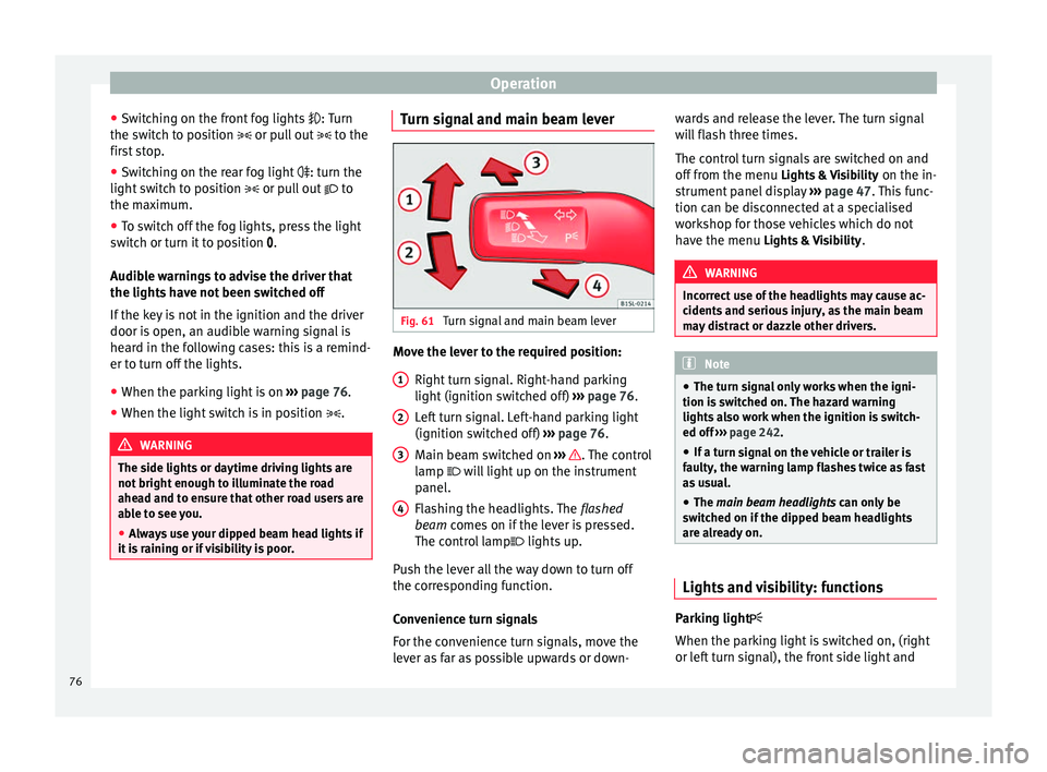
Fig. 61
Turn signal and main beam lever Move the lever to the required position:
Right turn signal. Right-hand parking
light (ignition switched off) ››› page 76.
Left turn signal. Left-hand parking light
(ignition switched off) ››› page 76.
Main beam switched on ››› . The control
lamp will light up on the instrument
panel.
Flashing the headlights. The flashed
beam comes on if the lever is pressed.
The c ontr
ol lamp lights up.
Push the lever all the way down to turn off
the corresponding function.
Convenience turn signals
For the convenience turn signals, move the
lever as far as possible upwards or down- 1 2
3
4 wards and release the lever. The turn signal
will flash three times.
The control turn signals are switched on and
off from the menu
Lights & Visibility on the in-
strument panel display ››› page 47. This func-
tion can be disconnected at a specialised
workshop for those vehicles which do not
have the menu Lights & Visibility
. WARNING
Incorrect use of the headlights may cause ac-
cidents and serious injury, as the main beam
may distract or dazzle other drivers. Note
● The turn signal only works when the igni-
tion is switched on. The hazard warning
lights also work when the ignition is switch-
ed off ››› page 242.
● If a t
urn signal on the vehicle or trailer is
faulty, the warning lamp flashes twice as fast
as usual.
● The main beam headlights can only be
sw
itched on if the dipped beam headlights
are already on. Lights and visibility: functions
Parking light
When the parking light is switched on, (right
or left turn signal), the front side light and
76
Page 79 of 305
Lights and visibility
the rear light on the corresponding side of
the vehicle stay lit. The parking lights will on-
ly work with the ignition off.
Daytime driving light
The daytime light reduces the risk of acci-
dents by increasing the visibility of the vehi-
cle. These are independent lights which are
built into the headlights and which come on
each time the ignition is turned on if the light
switch is in position or 0
.
When the light
switch is in position , a
photo sensor automatically turns the instru-
ment and switch lighting on and off.
Automatic dipped beam control
The automatic dipped beam control is merely
intended as an aid and is not able to recog-
nise all driving situations.
When the light switch is in position , the
vehicle lights and the instrument panel and
switch lighting switch on and off automatical-
ly in the following situations ››› :
Automatic switching
onAutomatic switching
off or switch to day-
time running lighting
The photo sensor detects
darkness, for example,
when driving through a
tunnel.When adequate lighting is
detected.
Automatic switching
onAutomatic switching
off or switch to day-
time running lighting
The rain sensor detects
rain and activates the
windscreen wipers.When the windscreen wip-
er has been inactive for a
few minutes. Adaptive headlights (AFS)
The adaptive headlights only operate when
the dipped beam is on and at speeds of over
10 km/h (6 mph). On bends, the adaptive
headlights automatically improve lighting on
the road ahead.
The adaptive headlights can be switched on
and off from the infotainment system.
Static turning lights
When turning slowly to change direction or
going round a tight bend, the static cornering
lights automatically come on. The static cor-
nering lights only work at speeds of less than
40 km/h (25 mph).
The static cornering lights may be incorpora-
ted into the fog lights or the front headlights,
depending upon the equipment.
WARNING
If the road is not well lit and other road users
cannot see the vehicle well enough or at all,
accidents may occur. ●
The automatic dipped beam control ( )
only switches on the dipped beam when
there are no changes in brightness, and not,
for example when it is foggy.
● Never drive with daytime lights if the road
is not well lit due to weather or lighting con-
ditions. Daytime lights do not provide
enough light to illuminate the road properly
or be seen by other road users.
● The rear lights do not come on with the
daytime driving light. A vehicle which does
not have the rear lights on may not be visible
to other drivers in the darkness, if it is rain-
ing or in conditions of poor visibility. Headlight adjustment
Headlight adjustment (Light Assist)
The headlight adjustment automatically con-
nects and disconnects these lights depend-
ing on the environmental and traffic condi-
tions and on the speed, within the limitations
of the system
››› . This is monitored by a
sensor located on the inside of the wind-
screen, above the interior rear vision mirror.
The automatic headlight adjustment auto-
matically switches on the lights depending
on the vehicles travelling in front and in the
opposite direction, and on other environmen-
tal and traffic conditions from an approxi-
mate speed of 60 km/h (37 mph) and turns »
77
Technical specifications
Advice
Operation
Safety
Page 80 of 305
Operation
them off again at speeds below approximate-
ly 30 km/h (18 mph).
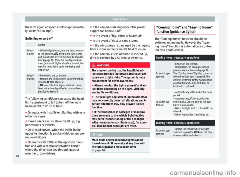
Switching on and off Action
Switch-
ing on:– With the ignition on, turn the lights control
to the position and put the turn signal
and main beam lever in the main beam posi-
tion ››› page 76. When the headlight adjust-
ment (automatic lights also) is activated, the
warning lamp lights up in the dash panel
display
.
Switch-
ing off:– Disconnect the on button.
– OR: turn the lights control to a different po-
sition to
››› page 75.
– OR: place the turn signal and main beam
lever in the headlight flasher or main beam
position ››› page 76. The following conditions can cause the head-
light adjustment to fail to turn off the main
beam or fail to do so in time:
●
On roads with insufficient lighting with very
reflective signs
● If road users are insufficiently lit up, e.g.
pedestrians or cyclists.
● On closed curves, when the traffic in the
opposite direction is partially hidden, on pro-
nounced slopes
● On roads with traffic in the opposite direc-
tion and with a central reservation barrier
where the driver can see through gaps or
over it e.g. lorry drivers. ●
If the camera is damaged or if the power
supply has been cut off
● In the event of fog, snow or heavy rain
● In the event of dust or sand storms
● If the windscreen is damaged by the impact
from a stone in the camera's field of vision
● If the camera's field of vision is misted up,
dirty or covered by a sticker, snow or ice. WARNING
The greater comfort that the headlight ad-
justment provides (automatic also) must not
cause you to take risks. The system is not a
replacement for driver awareness.
● Always monitor the lights yourself and ad-
just them depending on the light, visibility
and traffic conditions.
● The headlight adjustment (automatic also)
may not correctly detect all situations and in
certain situations may only provide limited
function.
● If the windscreen is damaged or modifica-
tions are made to the vehicle lighting, this
may harm the functioning of the headlight
adjustment (automatic lights also), for exam-
ple, if additional headlight are fitted. Note
Main beam and flashed headlights can be
turned on and off manually at any time with
the turn signal and main beam lever
››› page 76. “Coming home” and “Leaving home”
function (guidance lights)
The “Coming home” function should be
switched on manually. However the “Leav-
ing home” function is automatically control-
led by a photo sensor.
Coming home: necessary operations
To switch sys-
tem on:
– Switch off the ignition.
– Briefly flash the headlights
for ap-
proximately one second ››› page 76.
The “Coming home” lighting comes on
when the driver door is opened. The
delay in switching off the headlights is
counted from when the last door or
boot hatch is closed.
To switch sys-
tem off:
– Automatically at the end of the delay
period.
– Automatically, if 30 seconds after
coming on, a vehicle door or the boot
hatch remains open.
– When the light switch is turned to po-
sition
.
– When the ignition is switched on.
Leaving home: necessary operations
To switch sys-
tem on:– Unlock the vehicle when the light
switch is in position and the pho-
to sensor detects darkness.78
Page 81 of 305
Lights and visibilityLeaving home: necessary operations
To switch sys-
tem off:
– Automatically, at the end of the delay
period.
– When the vehicle is locked.
– When the light switch is turned to po-
sition
.
– When the ignition is switched on. Lighting around the exterior mirrors
The lighting around the exterior mirrors illu-
minates the door area on entering and leav-
ing the vehicles. It comes on when the vehi-
cle is unlocked, when the vehicle door is
opened and when the “Coming home” or
“Leaving home” function is switched on. If
the equipment includes the light sensor, the
lighting around the exterior mirrors only
comes when it is dark.
Note
● The time taken for the headlights to go off
can be changed in the Lights & Visibility menu
and the f u
nction can be switched on or off
››› page 47.
● When the “Comin
g home” function is on, if
the vehicle door is opened there is no audible
warning signal to advise that the light is still
on. Adhesive strips for headlights or
adjusting headlights
In those countries where vehicles drive on
the other side of the road to the home coun-
try, the asymmetric dipped beam may dazzle
drivers of oncoming vehicles. Therefore,
when driving abroad, adhesive strips should
be attached to the headlights or the head-
lights should be adjusted accordingly.
The direction of the headlights can be adjus-
ted from the instrument panel, in the
Tourist
light submenu of the Configuration menu
››› page 51
.
F or tho
se vehicles in which it is not possible
to adjust the headlights from the menu, ad-
hesive strips are used to cover certain parts
of the headlamp cover or the headlights may
be adjusted at a specialised workshop. For
further information, please refer to a special-
ised workshop. SEAT recommends visiting a
technical service. Note
Use of the Tourist light option and the adhe-
sives on the headlights is only allowed if they
are to be used for a short period of time. To
modify the direction of the headlights perma-
nently, please take the vehicle to a special-
ised workshop. SEAT recommends visiting a
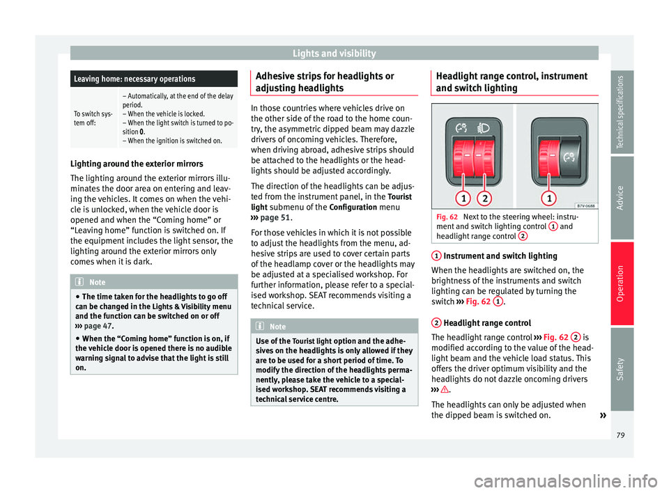
technical service centre. Headlight range control, instrument
and switch lighting
Fig. 62
Next to the steering wheel: instru-
ment and switch lighting control 1 and
headlight range control 2 1
Instrument and switch lighting
When the headlights are switched on, the
brightness of the instruments and switch
lighting can be regulated by turning the
switch ››› Fig. 62 1 .
2 Headlight range control
The headlight range control ››› Fig. 62 2 is
modified according to the value of the head-
light beam and the vehicle load status. This
offers the driver optimum visibility and the
headlights do not dazzle oncoming drivers
››› .
The headlights can only be adjusted when
the dipped beam is switched on. »
79
Technical specifications
Advice
Operation
Safety
Page 82 of 305
Operation
To reset, turn switch ››› Fig. 62 2 :ValueVehicle load status
a)
–Two front occupants, luggage compart-
ment empty
1All seats occupied, luggage compartment
empty
2All seats occupied, luggage compartment
full With trailer and minimum drawbar load
3Driver only, luggage compartment full With
trailer and maximum drawbar load
a)
If the vehicle load does not correspond to those shown in the
table, it is possible to select intermediary positions.
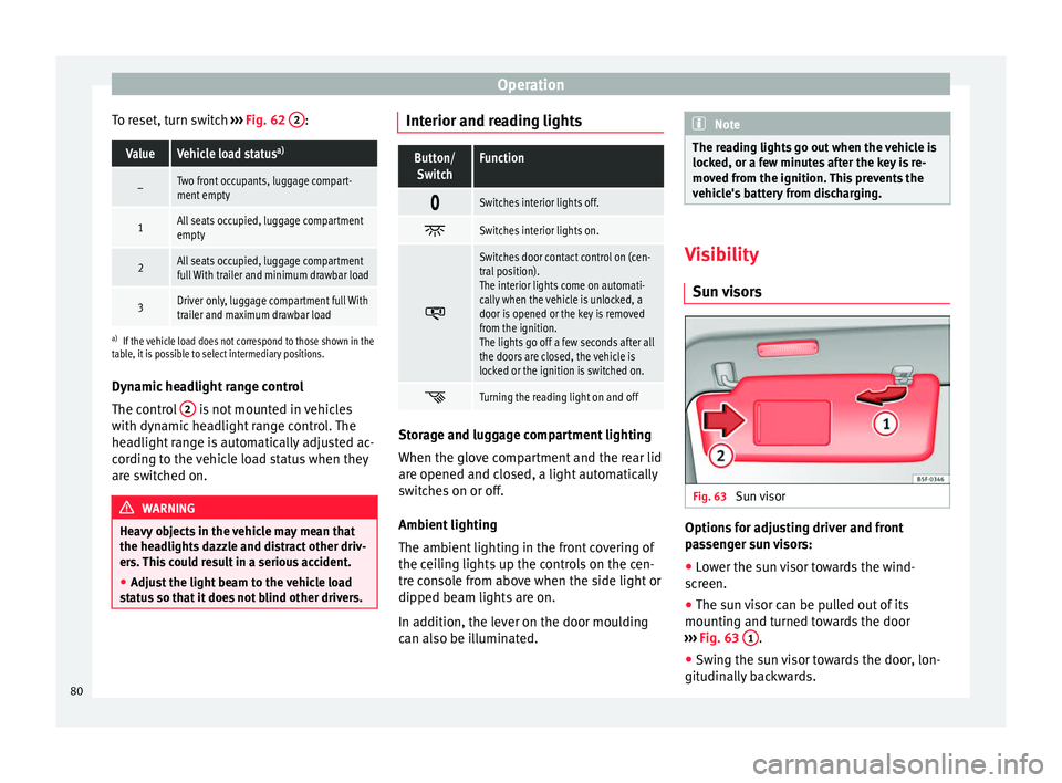
Dynamic headlight range control
The control 2 is not mounted in vehicles
with dynamic headlight range control. The
headlight range is automatically adjusted ac-
cording to the vehicle load status when they
are switched on. WARNING
Heavy objects in the vehicle may mean that
the headlights dazzle and distract other driv-
ers. This could result in a serious accident.
● Adjust the light beam to the vehicle load
status so that it does not blind other drivers. Interior and reading lights
Button/
SwitchFunction
Switches interior lights off.
Switches interior lights on.
Switches door contact control on (cen-
tral position).
The interior lights come on automati-
cally when the vehicle is unlocked, a
door is opened or the key is removed
from the ignition.
The lights go off a few seconds after all
the doors are closed, the vehicle is
locked or the ignition is switched on.
Turning the reading light on and off
Storage and luggage compartment lighting
When the glove compartment and the rear lid
are opened and closed, a light automatically
switches on or off.
Ambient lighting
The ambient lighting in the front covering of
the ceiling lights up the controls on the cen-
tre console from above when the side light or
dipped beam lights are on.
In addition, the lever on the door moulding
can also be illuminated. Note
The reading lights go out when the vehicle is
locked, or a few minutes after the key is re-
moved from the ignition. This prevents the
vehicle's battery from discharging. Visibility
Sun visors Fig. 63
Sun visor Options for adjusting driver and front
passenger sun visors:
● Lower the sun visor towards the wind-
screen.
● The sun visor can be pulled out of its
mounting and turned towards the door
››› Fig. 63 1 .
● Swing the sun visor towards the door, lon-
gitudinally backwards.
80
Page 85 of 305
Lights and visibility
Windscreen wiper functionsWindscreen wiper performance in different sit-
uations
If the vehicle
is at a stand-
stillThe activated position provisionally
changes to the previous position.
During auto-
matic wipe
The air conditioner comes on for ap-
proximately 30 seconds in air recircula-
tion mode to prevent the smell of the
windscreen washer fluid entering the
inside the vehicle.
For the inter-
val wipeIntervals between wipes depend on the
vehicle's speed. The higher the vehicle
speed the shorter the intervals. Heated windscreen washer jets
The heating only thaws the frozen jets, it
does not thaw the water in the washer hoses.
The heated windscreen washer jets automati-
cally adjust the heat depending on the ambi-
ent temperature, when the ignition is switch-
ed on.
Headlight wash/wipe system
The headlight washers/wipers clean the
headlight lenses.
After the ignition is switched on, the first and
every fifth time the windscreen washer is
switched on, the headlights are also washed.
Therefore, the windscreen wiper lever should
be pulled towards the steering wheel when the dipped beam or main beam are on. Any
incrusted dirt (such as insects) should be
cleaned regularly (e.g. when refuelling).
To ensure the headlight washers work cor-
rectly in winter, any snow which has got into
the bumper jet supports should be cleaned
away. If necessary, remove snow with an anti-
icing spray.
Note
The wiper will try to wipe away any obstacles
that are on the windscreen. The wiper will
stop moving if the obstacle blocks its path.
Remove the obstacle and switch the wiper
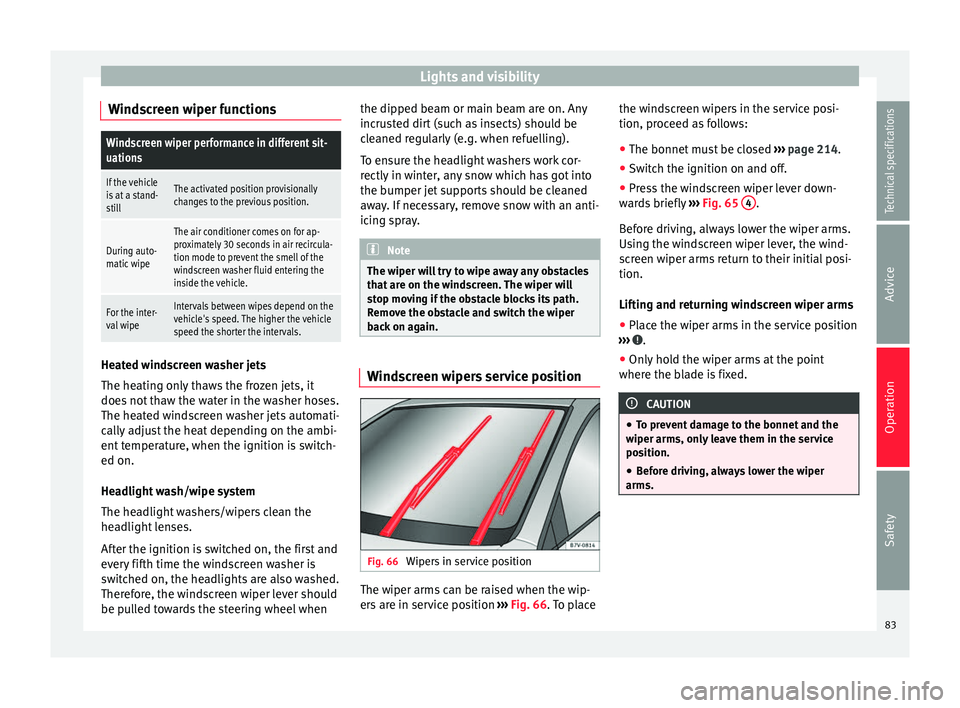
back on again. Windscreen wipers service position
Fig. 66
Wipers in service position The wiper arms can be raised when the wip-
ers are in service position
››› Fig. 66 . To place the w
ind
screen wipers in the service posi-
tion, proceed as follows:
● The bonnet must be closed ››› page 214.
● Switch the ignition on and off.
● Press the windscreen wiper lever down-
wards briefly ››› Fig. 65 4 .
Before driving, always lower the wiper arms.
Using the windscreen wiper lever, the wind-
screen wiper arms return to their initial posi-
tion.
Lifting and returning windscreen wiper arms
● Place the wiper arms in the service position
››› .
● Only hold the wiper arms at the point
where the blade is fixed. CAUTION
● To prevent damage to the bonnet and the
wiper arms, only leave them in the service
position.
● Before driving, always lower the wiper
arms. 83
Technical specifications
Advice
Operation
Safety
Page 133 of 305
Driving
Operating instructions The auxiliary heater exhaust system located
below the vehicle must be kept clear of snow,
mud and other objects. The exhaust gases
must not be obstructed in any way. The ex-
haust gases generated by the auxiliary heater
are removed via an exhaust pipe fitted under-
neath the vehicle.
On heating the vehicle interior, depending on
the outside temperature the warm air is first
directed at the windscreen and then to the
rest of the vehicle interior through the air
vents. If the air vents are turned towards the
windows, for example, the form of air distri-
bution may be affected.
Depending on the outside temperature, the
temperature at which the auxiliary heater
warms the vehicle interior may be somewhat
higher if the heating or air conditioner tem-
perature control is set to maximum before
switching the heating on.
Depending on the engine, vehicles with aux-
iliary heater may be fitted with a second bat-
tery in the luggage compartment that is re-
sponsible for powering the auxiliary heater.
Cases in which the auxiliary heater will not
switch on
● The auxiliary heater requires about as
much power as the dipped beam headlights.
If the battery charge is low, the auxiliary heat- er will switch off automatically or will not
even switch on. This avoids problems when
starting the engine.
●
The heater will switch on just once each
time. The timer will also have to be switched
back on every time it is required. Note
● Noise will be heard while the auxiliary
heater is running.
● When the air humidity is high and the out-
side temperature low, the heating system
may evaporate condensation from the auxili-
ary heater. In this case, steam may be re-
leased from underneath the vehicle. This is
completely normal and there is no need to
suspect a fault!
● If the auxiliary heater runs several times
over a prolonged period, the vehicle battery
may run flat. To re-charge the battery, drive
the vehicle for a long distance. As a general
rule, drive for as much time as the auxiliary
heating was working. Driving
Address Introduction The power steering is not hydraulic but elec-
tromechanical. The advantage of this steer-
ing system is that it disposes of hydraulic
tubes, hydraulic oil, the pump, filter and oth-
er components. The electromechanical sys-
tem saves fuel. While a hydraulic system re-
quires oil pressure to be maintained, electro-
mechanical steering only requires energy
when the steering wheel is turned.
With the power steering system, the assisted
steering function automatically adjusts ac-
cording to the vehicle speed, the steering tor-
que and the wheel turning angle. The power
steering only works when the engine is run-
ning.
WARNING
If the power steering is not working then the
steering wheel is much more difficult to turn
and the vehicle more difficult to control.
● The power steering only works when the
engine is running.
● Never allow the vehicle to move when the
engine is switched off.
● Never remove the key from the ignition if
the vehicle is in motion. The steering may » 131Technical specifications
Advice
Operation
Safety
Page 187 of 305
Towing bracket device
●
With the engine running, the electrical
equipment on the trailer will be supplied with
power. Loading the trailer
Trailer weight / drawbar load
The trailer weight is the load that the vehicle
can pull
››› . The drawbar load is the vertical
weight of the tow hitch on the tow hitch ball
››› page 188.
The figur e
s for trailer weights and drawbar
load weights given on the data plate of the
tow hitch are for values of this model only.
The correct figures for your specific vehicle,
which may be lower than these figures for the
t o
w hitch, are given in the vehicle documen-
tation. The instructions in the official vehicle
documents take precedence.
For the sake of road safety, SEAT recom-
mends using the maximum allowed drawbar
load
. The handling of the combined vehicle
and trailer will be poor if the drawbar load is
too low.
The drawbar load increases the weight on the
rear axle, reducing the vehicle carrying ca-
pacity.
Gross combination weight
This figure refers to the combined weight of
the loaded vehicle and loaded trailer. Loading the trailer
The combined vehicle and trailer must be
balanced. Use the maximum drawbar load
authorised and do not overload the front or
the rear of the trailer:
●
Distribute loads in the trailer so that heavy
objects are as near to the axle as possible or
above it.
● Correctly secure the trailer load.
Tyre pressure
Inflate the trailer tyres according to the man-
ufacturer's instructions.
Inflate the towing vehicles tyres to the maxi-
mum ››› page 231. WARNING
Exceeding the maximum authorised axle
load, drawbar load or the gross combination
weight of the towing vehicle and trailer could
cause a serious accident with severe conse-
quences.
● Never exceed the specifications.
● With the actual load on the front and rear
axles, the maximum axle load should never
be exceeded. The weight on the front and rear
should never exceed the gross vehicle
weight. WARNING
If the load moves, the stability and safety of
the vehicle and trailer combination will be se-
riously affected and this could result in a seri-
ous accident.
● Always correctly load the trailer.
● Always secure loads correctly with suitable
and undamaged attachment rope or straps. Driving with a trailer
Adjusting the headlights
When towing a trailer, the front of the vehicle
may rise and so the dipped beam headlights
may blind other drivers. Use the headlight
range control to lower the cone of light. If you
do not have headlight range control, have
the headlights adjusted by a specialised
workshop. Vehicles with high-intensity dis-
charge lamps adapt automatically and do not
require adjustment.
Details of driving with a trailer
● If the trailer has an overrun brake, apply
the brakes gently at first and then, firmly.
This will prevent the jerking that can be
caused by the trailer wheels locking.
● As of the combined vehicle and trailer
mass, braking distances will be greater.
● Select a low gear before driving down a
steep hill to use the engine braking effect to »
185
Technical specifications
Advice
Operation
Safety