gearbox Seat Alhambra 2017 Owner's Manual
[x] Cancel search | Manufacturer: SEAT, Model Year: 2017, Model line: Alhambra, Model: Seat Alhambra 2017Pages: 320, PDF Size: 6.88 MB
Page 5 of 320
Table of Contents
Table of Contents
The e s
senti
als . . . . . . . . . . . . . . . . . . . . . . . . 5
Exterior view . . . . . . . . . . . . . . . . . . . . . . . . . . . . 5
Exterior view . . . . . . . . . . . . . . . . . . . . . . . . . . . . 6
Interior view (left-hand drive) . . . . . . . . . . . . . . 7
How it works . . . . . . . . . . . . . . . . . . . . . . . . . . . . 8
Unlocking and locking . . . . . . . . . . . . . . . . . . . . 8
Before driving . . . . . . . . . . . . . . . . . . . . . . . . . . . 13
Airbags . . . . . . . . . . . . . . . . . . . . . . . . . . . . . . . . 17
Child seats . . . . . . . . . . . . . . . . . . . . . . . . . . . . . 21
Starting the vehicle . . . . . . . . . . . . . . . . . . . . . . 24
Lights and visibility . . . . . . . . . . . . . . . . . . . . . . 24
SEAT information system . . . . . . . . . . . . . . . . . . 26
Cruise control . . . . . . . . . . . . . . . . . . . . . . . . . . . 32
Warning lamps . . . . . . . . . . . . . . . . . . . . . . . . . . 32
Gearbox lever . . . . . . . . . . . . . . . . . . . . . . . . . . . 34
Air conditioning . . . . . . . . . . . . . . . . . . . . . . . . . 36
Fluid Level control . . . . . . . . . . . . . . . . . . . . . . . 39
Emergencies . . . . . . . . . . . . . . . . . . . . . . . . . . . . 42
Fuses . . . . . . . . . . . . . . . . . . . . . . . . . . . . . . . . . . 42
Bulbs . . . . . . . . . . . . . . . . . . . . . . . . . . . . . . . . . . 43
Action in the event of a puncture . . . . . . . . . . . 44
Changing a wheel . . . . . . . . . . . . . . . . . . . . . . . 45
Snow chains . . . . . . . . . . . . . . . . . . . . . . . . . . . . 49
Emergency towing of the vehicle . . . . . . . . . . . 50
How to jump start . . . . . . . . . . . . . . . . . . . . . . . . 51
Changing windscreen wipers . . . . . . . . . . . . . . 54
Safety . . . . . . . . . . . . . . . . . . . . . . . . . . . . . . . . 56
Safe driving . . . . . . . . . . . . . . . . . . . . . . . . . . . . 56
Safety first! . . . . . . . . . . . . . . . . . . . . . . . . . . . . . 56
Advice about driving . . . . . . . . . . . . . . . . . . . . . 56
Correct position of the vehicle occupants . . . . 57
Pedal area . . . . . . . . . . . . . . . . . . . . . . . . . . . . . . 60 Seat belts
. . . . . . . . . . . . . . . . . . . . . . . . . . . . . . 61
Why wear a seat belt? . . . . . . . . . . . . . . . . . . . . 61
How to properly adjust your seatbelt . . . . . . . . 64
Seat belt tensioners . . . . . . . . . . . . . . . . . . . . . . 67
Airbag system . . . . . . . . . . . . . . . . . . . . . . . . . . 68
Brief introduction . . . . . . . . . . . . . . . . . . . . . . . . 68
Airbag safety instructions . . . . . . . . . . . . . . . . . 71
Deactivating airbags . . . . . . . . . . . . . . . . . . . . . 72
Transporting children safely . . . . . . . . . . . . . . . 74
Safety for children . . . . . . . . . . . . . . . . . . . . . . . 74
Child seats . . . . . . . . . . . . . . . . . . . . . . . . . . . . . 75
Integrated child seat . . . . . . . . . . . . . . . . . . . . . 78
Emergencies . . . . . . . . . . . . . . . . . . . . . . . . . . 82
Self-help . . . . . . . . . . . . . . . . . . . . . . . . . . . . . . . 82
In case of emergency . . . . . . . . . . . . . . . . . . . . . 82
Vehicle tool kit* . . . . . . . . . . . . . . . . . . . . . . . . . 82
Changing a wheel* . . . . . . . . . . . . . . . . . . . . . . . 84
Tyre repair . . . . . . . . . . . . . . . . . . . . . . . . . . . . . . 85
Changing the windscreen wiper blades . . . . . . 87
Tow-starting and towing . . . . . . . . . . . . . . . . . . 87
Emergency locking and unlocking . . . . . . . . . . 89
Fuses and bulbs . . . . . . . . . . . . . . . . . . . . . . . . . 90
Fuses . . . . . . . . . . . . . . . . . . . . . . . . . . . . . . . . . . 90
Changing bulbs . . . . . . . . . . . . . . . . . . . . . . . . . 91
Operation . . . . . . . . . . . . . . . . . . . . . . . . . . . . . 99
General instrument panel . . . . . . . . . . . . . . . . . 99
Instrument panel . . . . . . . . . . . . . . . . . . . . . . . . 98
Instruments . . . . . . . . . . . . . . . . . . . . . . . . . . . . 100
Control lamps . . . . . . . . . . . . . . . . . . . . . . . . . . . 105
Communications and multimedia . . . . . . . . . . . 106
Steering wheel controls* . . . . . . . . . . . . . . . . . . 106
Multimedia . . . . . . . . . . . . . . . . . . . . . . . . . . . . . 108
Three button unit in headliner . . . . . . . . . . . . . . 108
Opening and closing . . . . . . . . . . . . . . . . . . . . . 110
Vehicle key set . . . . . . . . . . . . . . . . . . . . . . . . . . 110
Central locking and locking system . . . . . . . . . 112 Doors . . . . . . . . . . . . . . . . . . . . . . . . . . . . . . . . . . 119
Sliding doors . . . . . . . . . . . . . . . . . . . . . . . . . . . 119
Rear lid . . . . . . . . . . . . . . . . . . . . . . . . . . . . . . . . 122
Electric windows . . . . . . . . . . . . . . . . . . . . . . . . . 125
Panoramic sliding sunroof* . . . . . . . . . . . . . . . . 126
Lights and visibility
. . . . . . . . . . . . . . . . . . . . . . 128
Lights . . . . . . . . . . . . . . . . . . . . . . . . . . . . . . . . . 128
Visibility . . . . . . . . . . . . . . . . . . . . . . . . . . . . . . . 134
Windscreen wiper and window wiper sys-
tems . . . . . . . . . . . . . . . . . . . . . . . . . . . . . . . . . . 135
R
ear vision mirror . . . . . . . . . . . . . . . . . . . . . . . . 137
Seats and head restraints . . . . . . . . . . . . . . . . . 140
Adjusting the seats and head restraints . . . . . . 140
Seat functions . . . . . . . . . . . . . . . . . . . . . . . . . . 144
Transport and practical equipment . . . . . . . . . 150
Transporting objects . . . . . . . . . . . . . . . . . . . . . 150
Luggage compartment . . . . . . . . . . . . . . . . . . . . 152
Roof carrier* . . . . . . . . . . . . . . . . . . . . . . . . . . . . 161
Storage compartments . . . . . . . . . . . . . . . . . . . 163
Drink holders . . . . . . . . . . . . . . . . . . . . . . . . . . . 168
Ashtray and cigarette lighter* . . . . . . . . . . . . . . 170
Power sockets . . . . . . . . . . . . . . . . . . . . . . . . . . . 170
Air conditioning . . . . . . . . . . . . . . . . . . . . . . . . . 173
Air conditioning . . . . . . . . . . . . . . . . . . . . . . . . . 173
Auxiliary heater* (additional heater) . . . . . . . . 177
Driving . . . . . . . . . . . . . . . . . . . . . . . . . . . . . . . . 181
Address . . . . . . . . . . . . . . . . . . . . . . . . . . . . . . . . 181
Stopping and starting the engine . . . . . . . . . . . 182
Braking and parking . . . . . . . . . . . . . . . . . . . . . 187
Gearbox . . . . . . . . . . . . . . . . . . . . . . . . . . . . . . . . 192
Run-in and economical driving . . . . . . . . . . . . . 197
Engine management and exhaust gas purifica-
tion syst
em . . . . . . . . . . . . . . . . . . . . . . . . . . . . . 200
Driving tips . . . . . . . . . . . . . . . . . . . . . . . . . . . . . 202
Driver assistance systems . . . . . . . . . . . . . . . . . 203
Braking and stability systems . . . . . . . . . . . . . . 203
Start assist systems . . . . . . . . . . . . . . . . . . . . . . 205
Parking distance warning system* . . . . . . . . . . 208 3
Page 26 of 320
The essentials
● Pu
sh the he
ad restraint down as far as it
will go. Ensure that it does not interfere with
the seatbelt from the upper attachment.
● Tighten the strap so that the top of the
chil
d seat rests on the seat backrest.
››› in Safety instructions on page 75 Starting the vehicle
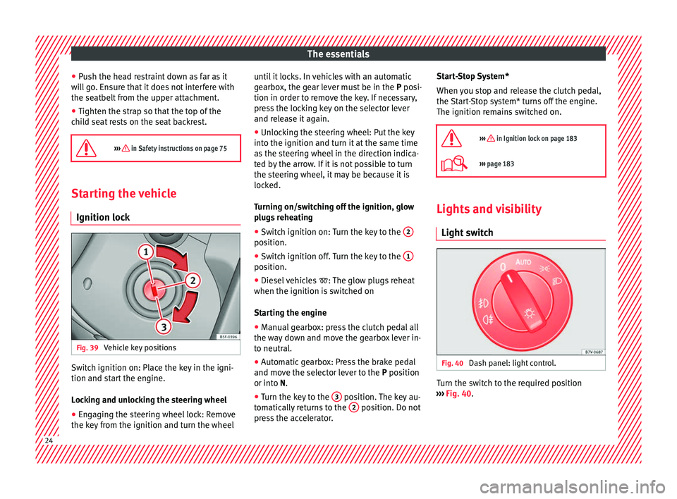
Ignition lock Fig. 39
Vehicle key positions Switch ignition on: Place the key in the igni-
tion and s
t
ar
t the engine.
Locking and unlocking the steering wheel
● Engaging the steering wheel lock: Remove
the key fr
om the ignition and turn the wheel until it locks. In vehicles with an automatic
gearbo
x, the gear lever must be in the P posi-
tion in order to remove the key. If necessary,
press the locking key on the selector lever
and release it again.
● Unlocking the steering wheel: Put the key
into the ignition and turn it
at the same time
as the steering wheel in the direction indica-
ted by the arrow. If it is not possible to turn
the steering wheel, it may be because it is
locked.
Turning on/switching off the ignition, glow
plugs reheating
● Switch ignition on: Turn the key to the 2 position.
●
Switch ignition off. Turn the key to the 1 position.
●
Diesel vehicles : The glo
w p
lugs reheat
when the ignition is switched on
Starting the engine
● Manual gearbox: press the clutch pedal all
the way
down and move the gearbox lever in-
to neutral.
● Automatic gearbox: Press the brake pedal
and move the sel
ector lever to the P position
or into N.
● Turn the key to the 3 position. The key au-
t om
atic
ally returns to the 2 position. Do not
pr e
s
s the accelerator. Start-Stop System*
When you s
top and release the clutch pedal,
the Start-Stop system* turns off the engine.
The ignition remains switched on.
››› in Ignition lock on page 183
››› page 183 Lights and visibility
Light sw
it
ch Fig. 40
Dash panel: light control. Turn the switch to the required position
› ›
›
Fig. 40. 24
Page 36 of 320
The essentials
Use the foot brake!
Change
››› page
192
Brake
››› page
187
Cruise control operating.›››
page
219
Lane Assist is switched on and
active.›››
page
220
Main beam on or flasher on.›››
page
128 Headlight adjustment (Light As-
sist) on.
Electronic immobiliser active.›››
page
182
Service interval display›››
page
103
Mobile telephone is connected
via Bluetooth to the original tel-
ephone device.›››
Book-
let Radio
or
››› Book-
let Navi-
gation
system
Mobile telephone battery charge
meter. Available only for pre-in-
stalled factory-fitted devices.
Freezing warning. The outside
temperature is lower than +4°C
(+39°F).›››
page
102
››› in Control and warning lamps on
page 105
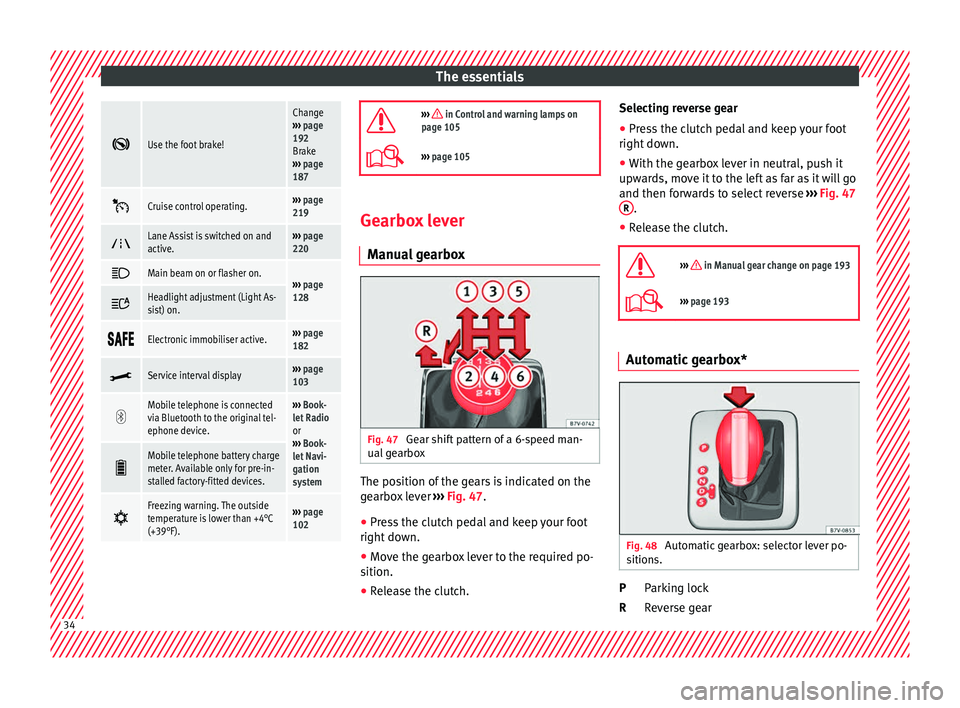
››› page 105 Gearbox lever
M anua
l
gearbox Fig. 47
Gear shift pattern of a 6-speed man-
ual g
e
arbox The position of the gears is indicated on the
g
e
arbo
x lever ››› Fig. 47.
● Press the clutch pedal and keep your foot
right down.
● Mo
ve the gearbox lever to the required po-
sition.
● Rel
ease the clutch. Selecting reverse gear
●
Press the clutch pedal and keep your foot
right down.
● W
ith the gearbox lever in neutral, push it
upwar
ds, move it to the left as far as it will go
and then forwards to select reverse ››› Fig. 47
R .
● Release the clutch.
››› in Manual gear change on page 193
››› page 193 Automatic gearbox*
Fig. 48
Automatic gearbox: selector lever po-
s ition
s. Parking lock
R
ev
er
se gear
P
R 34
Page 37 of 320
The essentials
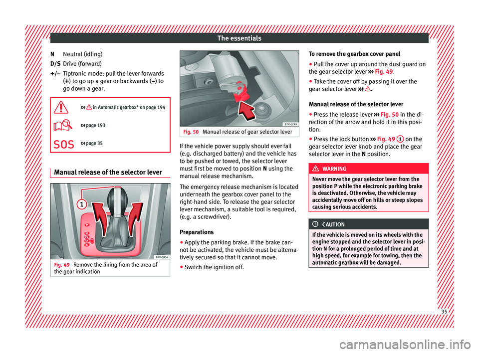
Neutral (idling)
Driv e (f
or
ward)
Tiptronic mode: pull the lever forwards
(+) to go up a gear or backwards ( –) to
go down a gear.
››› in Automatic gearbox* on page 194
››› page 193
››› page 35 Manual release of the selector lever
Fig. 49
Remove the lining from the area of
the g e
ar indic
ation N
D/S
+/–
Fig. 50
Manual release of gear selector lever If the vehicle power supply should ever fail
(e.
g. di
s
charged battery) and the vehicle has
to be pushed or towed, the selector lever
must first be moved to position N using the
manual release mechanism.
The emergency release mechanism is located
underneath the gearbox cover panel to the
right-hand side. To release the gear selector
lever mechanism, a suitable tool is required,
(e.g. a screwdriver).
Preparations
● Apply the parking brake. If the brake can-
not be activat
ed, the vehicle must be alterna-
tively secured so that it cannot move.
● Switch the ignition off. To remove the gearbox cover panel
●
Pull the cover up around the dust guard on
the gear sel
ector lever ››› Fig. 49.
● Take the cover off by passing it over the
gear sel
ector lever ››› .
M anua
l
release of the selector lever
● Press the release lever ›››
Fig. 50 in the di-
rection of the arrow and hold it in this posi-
tion.
● Press the lock button ›››
Fig. 49 1 on the
g e
ar sel
ector lever knob and place the gear
selector lever in the N position. WARNING
Never move the gear selector lever from the
pos ition P whi
le the electronic parking brake
is deactivated. Otherwise, the vehicle may
accidentally move off on hills or steep slopes
causing serious accidents. CAUTION
If the vehicle is moved on its wheels with the
engine s t
opped and the selector lever in posi-
tion N for a prolonged period of time and at
high speed, for example for towing, then the
automatic gearbox will be damaged. 35
Page 46 of 320
The essentials
Action in the event of a punc-
t ur
e
Wh
at to do first ●
Park the vehicle on a horizontal surface
and in a saf e p
lace as far away from traffic as
possible.
● Apply the handbrake.
● Switch on the hazard warning lights.
● Manual gearbox: select the 1s
t gear.
● Automatic gearbox: Move the sel
ector lever
to position P.
● If you are towing a trailer, unhitch it from
your v
ehicle.
● Keep the vehicle tool kit ready*
›››
page 82.
● Observe the applicable legislation for each
countr
y (reflective vest, warning triangles,
etc.).
● All occupants should leave the vehicle and
wait in a s
afe place (for instance behind the
roadside crash barrier). WARNING
● Alw a
ys observe the above steps and pro-
tect yourself and other road users.
● If you change the wheel on a slope, block
the wheel on the oppo
site side of the car with
a stone or similar to prevent the vehicle from
moving. Repairing a tyre with the anti-punc-
t
ur
e k
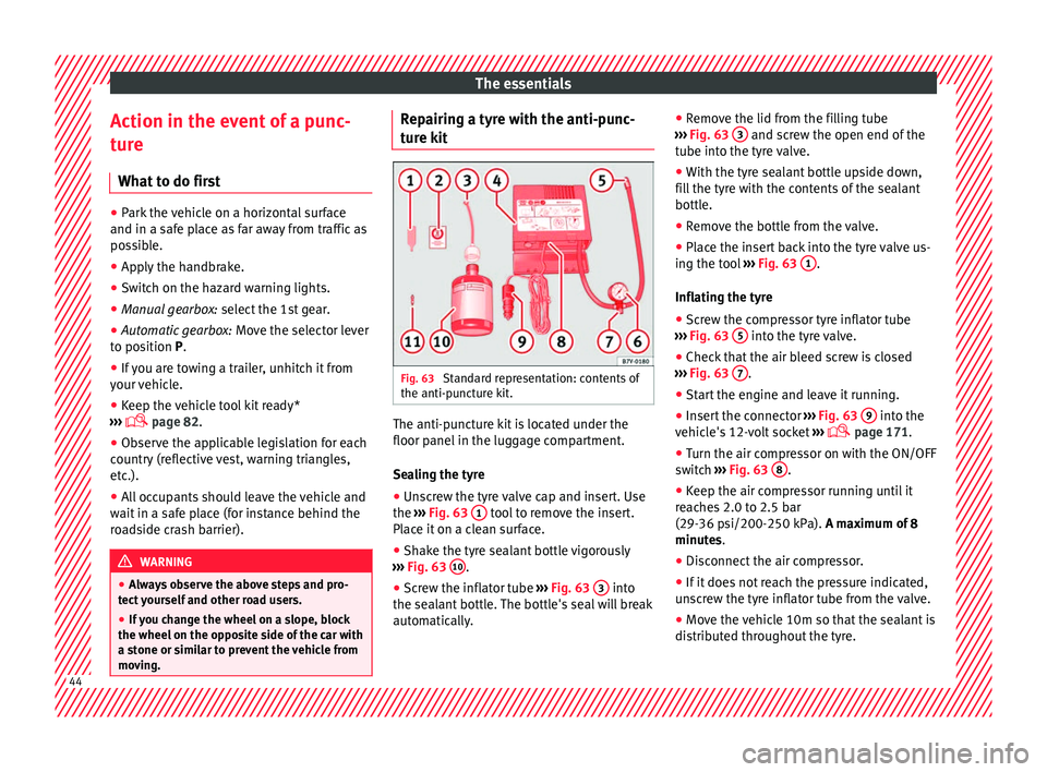
it Fig. 63
Standard representation: contents of
the anti-p u
nct
ure kit. The anti-puncture kit is located under the
floor p
anel
in the lug
gage compartment.
Sealing the tyre
● Unscrew the tyre valve cap and insert. Use
the ›››
Fig. 63 1 tool to remove the insert.
Pl ac
e it
on a clean surface.
● Shake the tyre sealant bottle vigorously
›››
Fig. 63 10 .
● Screw the inflator tube ››
›
Fig. 63 3 into
the se al
ant
bottle. The bottle's seal will break
automatically. ●
Remov
e the lid from the filling tube
››› Fig. 63 3 and screw the open end of the
t ube int
o the ty
re valve.
● With the tyre sealant bottle upside down,
fill
the tyre with the contents of the sealant
bottle.
● Remove the bottle from the valve.
● Place the insert back into the tyre valve us-
ing the too
l ››› Fig. 63 1 .
Infl atin
g the ty
re
● Screw the compressor tyre inflator tube
›››
Fig. 63 5 into the tyre valve.
● Check that the air bleed screw is closed
› ›
›
Fig. 63 7 .
● Start the engine and leave it running.
● Insert the connector ››
›
Fig. 63 9 into the
v ehic
l
e's 12-volt socket ›››
page 171.
● Turn the air compressor on with the ON/OFF
switc
h ››› Fig. 63 8 .
● Keep the air compressor running until it
r e
ac
hes 2.0 to 2.5 bar
(29-36 psi/200-250 kPa). A maximum of 8
minutes.
● Disconnect the air compressor.
● If it does not reach the pressure indicated,
uns
crew the tyre inflator tube from the valve.
● Move the vehicle 10m so that the sealant is
dis trib
uted throughout the tyre.44
Page 50 of 320
The essentials
The jack may be applied only at the jacking
points sho
wn (m
arks on chassis) ››› Fig. 69.
The mark indicates the jacking points below
the vehicle. The jacking points are on the ribs
behind the front edges ››› Fig. 70. Always the
relevant jacking point for the wheel to be
changed ››› .
R ai
se the
vehicle using only the designated
jacking points.
For your own safety and that of other passen-
gers, the following points should be ob-
served in the order given:
Select a suitable flat and firm surface for
raising the vehicle.
Switch off the engine, engage a gear
(manual gearbox) or place the selector
lever in position P ›››
page 192 and
turn on the electronic parking brake
››› page 187.
Block the wheel diagonally opposite the
wheel being changed with folding wheel
chocks* or other suitable objects.
When towing a trailer: unhook the trailer
from the towing vehicle and park it cor-
rectly.
Loosen the wheel bolts on the wheel to
be changed ››› page 46.
Look below the vehicle for the jacking
point ››› Fig. 69 closest to the tyre which
has to be changed.
1.
2.
3.
4.
5.
6. Raise the jack with the handle until it
can be inser
ted below the jacking point.
Ensure that the foot of the jack is firmly
on the ground and that it is placed im-
mediately below the lifting point on the
vehicle ››› Fig. 70.
Straighten the jack and continue raising
it using the handle until the claw holds
the vertical reinforcement beneath the
vehicle ››› Fig. 70.
Raise the vehicle until the wheel is clear
of the ground. WARNING
If the vehicle is not correctly raised, it could
fa l
l off the jack causing serious injury. Please
observe the following rules to minimise the
risk of injury:
● You should only use a jack approved by
SEAT f
or your vehicle. Other jacks, even those
approved for other SEAT models, might slip
out of place.
● The ground should be firm and flat. If the
ground i
s sloped or soft then the vehicle
could slip and fall off the jack. If necessary,
support the jack on a wide solid base.
● If the ground is slippery, such as tiles,
plac
e a non-slip surface (a floor mat, for in-
stance) beneath the jack to avoid slipping.
● Only fit the jack at the prescribed jacking
points. The c
law of the jack should grip the
reinforcement nerve on the underbody
››› Fig. 70. 7.
8.
9.
10.
●
You shou l
d never place a body limb such as
an arm or leg under a raised vehicle that is
solely supported by the jack.
● If you have to work underneath the vehicle,
you mus
t use suitable stands additionally to
support the vehicle, there is a risk of acci-
dent!.
● Never raise the vehicle if it is tilting to one
side or the engine i
s running.
● Never start the engine when the vehicle is
raised.
The vehicle may come loose from the
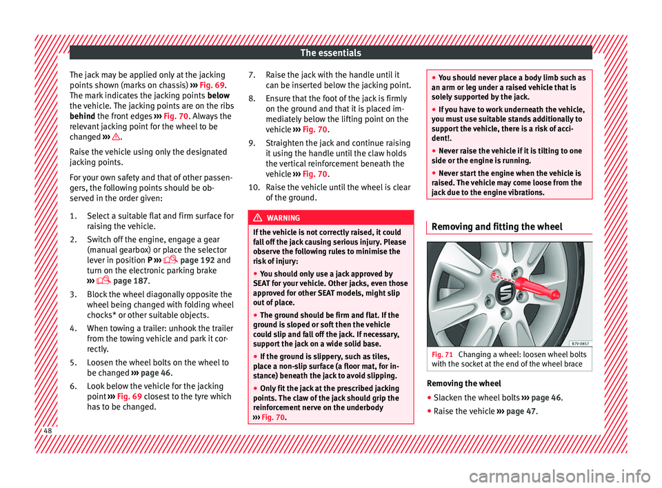
jack due to the engine vibrations. Removing and fitting the wheel
Fig. 71
Changing a wheel: loosen wheel bolts
w ith the soc
k
et at the end of the wheel brace Removing the wheel
● Slacken the wheel bolts ››
›
page 46.
● Raise the vehicle ›››
page 47. 48
Page 53 of 320
The essentials
Only secure the tow rope or tow bar to the
t o
wline anc
horage or specially designed fit-
ting.
Vehicles with a factory fitted towing device ,
can only be used for towing with a tow bar,
specially designed to fit on a tow hitch ball
››› page 234.
Towing vehicles with an automatic gearbox
Note the following for a towed vehicle: ● Make sure the gear selector lever is in the N
position.
● Do not
drive faster than 50 km/h (30 mph).
● Do not tow further than 50 km (30 miles).
● If a breakdown truck is used, the vehicle
must
be towed with the front wheels raised.
Note the following instructions for towing
four all-wheel drive vehicles.
Instructions for towing all-wheel drive vehi-
cles
All-wheel drive vehicles can be towed using a
toolbar or tow rope. If the vehicle is towed
with the front or rear axle raised, the engine
must be turned off to avoid transmission
damage.
For vehicles with a double clutched DSG ®
(di-
rect shift gearbox) the instructions for towing
vehicles with an automatic gearbox apply
››› page 51. Situations in which a vehicle should not be
tow
ed
In the following cases, the vehicle should not
be towed but transported on a trailer or spe-
cial vehicle:
● If the vehicle gearbox does not contain lu-
bricant due t
o a fault.
● If the vehicle battery is flat and, as a result,
the electronic
steering lock and electronic
parking brake cannot be disengaged if ap-
plied.
● If the vehicle to be towed has an automatic
gearbo
x and the distance to be covered is
greater than 50 km (30 miles).
››› in Introduction on page 87
››› page 87 Tow-starting
In general, the vehicle should not be started
b
y
t
owing. Jump-starting is much more pref-
erable ›››
page 51.
For technical reasons, the following vehicles
can not be tow started:
● Vehicles with an automatic gearbox. ●
Vehicl
es with the Keyless Access locking
and ignition system, since the electronic
steering lock may not unlock.
● Vehicles with an electronic parking brake,
given that
it is possible that the brake will
not be disengaged.
● If the vehicle battery is flat, it is possible
that the en
gine control units do not operate
correctly.
However, if your vehicle must absolutely be
tow-started (manual gearbox):
● Put it into second or third gear.
● Keep the clutch pressed down.
● Switch on the ignition and the hazard warn-
ing lights.
● Rel
ease the clutch when both vehicles are
movin
g.
● As soon as the engine starts, press the
clutc
h and move the gear lever into neutral.
This helps to prevent a collision with the tow-
ing vehicle.
How to jump start
Jump lea
ds If the engine fails to start because of a dis-
c
h
ar
ged battery, the battery of another vehi-
cle can be used to start the engine. Before » 51
Page 86 of 320
Emergencies
The chocks should be placed directly in front
and behind the wheel and on
ly
be used on
firm ground. WARNING
If the folding chocks are assembled or used
incorr ectly
, an accident may occur and seri-
ous injury caused.
● Never use damaged chocks.
● Never use chocks to immobilize the vehicle
on a slope. Changing a wheel*
Intr oduction Read the additional information carefully
› ›
›
page 45
All Alhambra models have TMS (Tyre Mobility
System).
If a tyre needs to be changed the tools neces-
sary are available at spare parts dealers:
● Jack,
● box spanner for wheel bolts,
● tool to remove wheel bolt caps
The tyre
s mounted on the vehicle are anti-
puncture. The wheels should only be
changed when switching from summer to
winter tyres or vice-versa. See ›››
page 290 The vehicle only comes with the necessary
tool
s for changing wheels if factory supplied
with winter tyres. If this is not the case, you
need to go to a specialised workshop to get
the wheels changed.
You should only change the wheels yourself if
the vehicle is parked in a safe place, you are
familiar with the procedure and safety stand-
ards and you have all the necessary tools!
Otherwise, you should seek professional as-
sistance. WARNING
Changing a wheel can be dangerous, espe-
ci a
lly on the hard shoulder. Please observe
the following rules to minimise the risk of in-
jury:
● Stop the vehicle safely as soon as possible.
Park at
a safe distance from surrounding traf-
fic to change a wheel.
● When changing a wheel, keep all passen-
gers, and p
articularly children, a safe dis-
tance away from the work area.
● Turn on the hazard warning lights to warn
other roa
d users.
● Ensure the ground on which you park is flat
and solid. If nec
essary, support the jack on a
wide solid base.
● If you are changing a wheel yourself, you
should be f
amiliar with the required proce-
dure. Otherwise, you should seek professio-
nal assistance. ●
Only u
se suitable tools that are not dam-
aged when changing a wheel.
● Always stop the engine, turn on the elec-
tronic p
arking brake and place the gear selec-
tor lever in position P, for an automatic gear-
box, or engage a gear for a manual gearbox to
reduce the risk of the vehicle moving acciden-
tally.
● Have the tightening torque of the wheel
bolts
checked as soon as possible with a reli-
able torque wrench. WARNING
If the wheel trims are not appropriate or not
fitted c orr
ectly, they could cause major acci-
dents or damage.
● Incorrectly mounted wheel trims may come
off whil
e driving and endanger other road
users.
● Damaged trims must never be mounted on
the wheels.
● Alw
ays ensure that the brake ventilation
and coolin
g is not cut off or blocked. This is
also valid if hubcaps are fitted later. If there
is not enough air, you may require signifi-
cantly longer braking distances. CAUTION
Remove and remount wheel trims taking care
to av oid d
amage to the vehicle.84
Page 87 of 320
Self-help
Tyre repair TM S
(T
yre Mobility System)* Read the additional information carefully
›› ›
page 44
The Anti-puncture kit* (Tyre Mobility System)
will reliably seal punctures caused by the
penetration of a foreign body of up to about
4 mm in diameter. Do not remove foreign ob-
jects, e.g. screws or nails, from the tyre.
Once the sealant is in the tyre, make sure to
check the pressure after 10 minutes driving.
If the vehicle has more than one damaged
tyre, seek professional assistance. The tyre
mobility system is designed for filling one
tyre.
Only use the tyre mobility system if the vehi-
cle is properly parked, you know how to do it
and the necessary safety measures, and if
you have the right kit! Otherwise, you should
seek professional assistance.
The tyre sealant should not be used in the
following cases:
● If the wheel is damaged.
● The outside temperature is lower than
-20°C (-4°F).
● If the t
ear or puncture on the tyre is over 4
mm wide. ●
If y
ou have driven with very low pressure or
a flat tyre.
● If the expiry date on the bottle of tyre seal-
ant ha
s passed. WARNING
Using the tyre mobility system can be dan-
ger ou
s, especially when filling the tyre at the
roadside. Please observe the following rules
to minimise the risk of injury:
● Stop the vehicle safely as soon as possible.
Park it
at a safe distance from surrounding
traffic to fill the tyre.
● Ensure the ground is flat and firm.
● All occupants, and especially children,
should a
lways be at a safe distance outside
the work area.
● Turn on the hazard warning lights to warn
other roa
d users.
● Use the tyre mobility system only if you are
famili
ar with the necessary procedures. Oth-
erwise, you should seek professional assis-
tance.
● Only use the tyre mobility system in the
event of
an emergency to get to the nearest
workshop.
● Replace the repaired tyre with the tyre mo-
bility
set as soon as possible.
● The sealant is hazardous for your health
and if it t
ouches your skin, it must be imme-
diately washed off. ●
Keep c hi
ldren away from the tyre mobility
system.
● Never use a jack even if it is approved for
the vehic
le.
● To reduce the risk of the vehicle possibly
movin
g on its own, always turn off the en-
gine, set the electronic parking brake and put
the selector lever in position P or put into
gear if the gearbox is a manual. WARNING
A tyre filled with sealant does not have the
s ame per f
ormance properties as a conven-
tional tyre.
● Never drive faster than 80 km/h (50 mph).
● Avoid heavy acceleration, hard braking and
fas
t cornering.
● Drive for only 10 minutes at a maximum
speed of 80
km/h (50 mph) and then check
the tyre. For the sake of the environment
Once used or expired, dispose of the sealant
acc or
ding to legal provisions. Note
● Sea l
ant bottles can be purchased from
SEAT dealers.
● Observe the usage instructions provided by
the snow c
hain manufacturer. 85
Technical data
Advice
Operation
Emergencies
Safety
Page 101 of 320

General instrument panel
Operation
Gener a
l
instrument panel
Instrument panel Interior door release lever
. . . . . . . . .119
Central lock button . . . . . . . . . . 112
Switch for adjusting the exterior
mirror s . . . . . . . . . . . . . . . . . . . . . . . . . . . 137
– Exterior mirr or a
djustment
– Heated exterior mirrors
– Folding exterior mirrors
Instrument panel controls and light-
ing control . . . . . . . . . . . . . . . . . . . . . 128
Headlamp range adjustment . . . 128
Light switch . . . . . . . . . . . . . . . . . . . 128
– Light off - -
– Aut
omatic dipped beam head-
light control - -
– Side/dipped lights
– Fog lights
Lever for . . . . . . . . . . . . . . . . . . . . . . . . . 128
– Main beam he
adlights
– Headlight flasher
– Turn signals
– Parking lights
Instrument panel:
1 2
3
4
5
6
7
8 –
Ins
truments . . . . . . . . . . . . . . . . . . . . 100
– Digit
al di
splay . . . . . . . . . . . . . . . . . . 100
– Warning and indic
ation lamps . . .105
Steering wheel with horn and – Driver airbag . . . . . . . . . . . . . . . . . . . 17
– On-bo
ard c
omputer controls . . . .26
– Contro
ls for radio, telephone,
navigation and speech dialogue
system ››› Booklet Radio
– Paddle levers for tiptronic gear-
shift (automatic gearbox) . . . . . . .195
Windscreen wiper/ windscreen
wash l
ever . . . . . . . . . . . . . . . . . . . . . . . 135
– Wind s
creen wipers –
– Intermittent wipe
– “Brief wipe” x
– Windscreen wipers
– Automatic windscreen wash/wipe
– Rear window wiper
– Automatic rear window
wash/wipe
– Lever with buttons for controlling
the SEAT information system - ,
/ . . . . . . . . . . . . . . . . . . . . . . . . . 26
Left seat heating controls . . . . . . . 144
Radio or navigation system (fitted
at fact
ory) ››› Booklet Radio or
››› Booklet Navigation system
9
10
11
12 Storage compartment
. . . . . . . . . . . . .163
Hazard warning lights switch . . . 82
Switches for:
– Electr
onic
manual air condition-
ing . . . . . . . . . . . . . . . . . . . . . . . . . . . . . 173
– Climatr
onic . . . . . . . . . . . . . . . . . . . . . 173
Right seat heating controls . . . . . 144
Button for:
– Anti-slip r
egulation (ASR) . .187
– Start
-Stop operation . . . . . . . . . .205
– Park in
g distance warning system
(Park Pilot) . . . . . . . . . . . . . . . . . . 208
– Park As
sist system . . . . . . . . . . . 211
– Tyr
e pressure monitor . . . . .231
– Dyn
amic chassis control (DCC)
– Opening the rear lid . . . . . . . . .122
– Opening and clo
sing of electric
sliding doors . . . . . . . . . . . . . . . . 119
Locking lever to open glove com-
par tment . . . . . . . . . . . . . . . . . . . . . . . . . 163
P
osition of passenger front airbag
on the dash p
anel . . . . . . . . . . . . . . . . 17
Key-operated switch in glove com-
partment
for deactivating front pas-
senger front airbag . . . . . . . . . . . . . . .18
Passenger front airbag off warning
lamp . . . . . . . . . . . . . . . . . . . . . . . . . . . . . 72
L ev
er for: »
13 14
15
16
17
18
19
20
21
22
99
Technical data
Advice
Operation
Emergencies
Safety