jump cable Seat Alhambra 2017 Owner's Manual
[x] Cancel search | Manufacturer: SEAT, Model Year: 2017, Model line: Alhambra, Model: Seat Alhambra 2017Pages: 320, PDF Size: 6.88 MB
Page 54 of 320

The essentials
starting, check the magic eye on the battery
› ›
›
page 280.
For starting assistance, jump lead cables con-
forming to the standard DIN 72553 are re-
quired (see the cable manufacturer instruc-
tions). The jump lead cable must be at least
25 mm 2
in section (0.038 inches 2
) for petrol
engines, and 35 mm 2
(0.054 inches 2
) for die-
sel engines.
For vehicles whose battery is not in the en-
gine compartment, the jump leads should
only be connected to the starting assistance
connection points in the engine compart-
ment. WARNING
Incorrect use of jump leads and incorrectly
jump st ar
ting could cause the battery to ex-
plode resulting in serious injury. Please ob-
serve the following rules to minimise the risk
of a battery explosion:
● The battery providing current must have
the same v
oltage (12V) and approximately
the same capacity (see markings on battery)
as the flat battery.
● Never charge a frozen or recently thawed
batter
y. A flat battery can also freeze at tem-
peratures close to 0°C (+32°F).
● If a battery is frozen and/or has been frozen
then it mus
t be replaced.
● A highly explosive mixture of gases is re-
lea
sed when the battery is being charged. Al- ways keep lit cigarettes, flames, sparks and
fire f
ar fr
om the battery. Never use a mobile
telephone when connecting and removing the
jump leads.
● Charge the battery only in well ventilated
area
s given that when the battery is charged
by outside assistance, it creates a mix of
highly explosive gases.
● Jump leads should never enter into contact
with mov
ing parts in the engine compart-
ment.
● Never switch the positive and negative
pole
s or connect the jump leads incorrectly.
● Note the instruction manual provided by
the manufact
urer of the jump leads. CAUTION
To avoid considerable damage to the vehicle
electric a
l system, note the following careful-
ly:
● If the jump leads are incorrectly connected,
this c
ould result in a short circuit.
● The vehicles must not touch each other,
otherwi
se electricity could flow as soon as
the positive terminals are connected. Positive pole on the jump lead con-
nection point
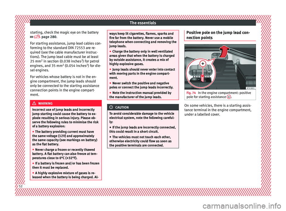
s Fig. 74
In the engine compartment: positive
po l
e f
or starting assistance + .
On some vehicles, there is a starting assis-
t
anc
e t
erminal in the engine compartment,
under a labelled cover. 52
Page 56 of 320

The essentials
on battery). Failure to comply could result in
an exp
lo
sion.
● Never use jump leads when one of the bat-
teries
is frozen. Danger of explosion! Even af-
ter the battery has thawed, battery acid could
leak and cause chemical burns. If a battery
freezes, it should be replaced.
● Keep sparks, flames and lighted cigarettes
awa
y from batteries, danger of explosion.
Failure to comply could result in an explo-
sion.
● Observe the instructions provided by the
manufact
urer of the jump leads.
● Do not connect the negative cable from the
other vehic
le directly to the negative terminal
of the flat battery. The gas emitted from the
battery could be ignited by sparks. Danger of
explosion.
● Do not attach the negative cable from the
other vehic
le to parts of the fuel system or to
the brake line.
● The non-insulated parts of the battery
clamp
s must not be allowed to touch. The
jump lead attached to the positive battery
terminal must not touch metal parts of the ve-
hicle, this can cause a short circuit.
● Position the leads in such a way that they
cannot c
ome into contact with any moving
parts in the engine compartment.
● Do not lean on the batteries. This could re-
sult
in chemical burns. Note
The vehicles must not touch each other, oth-
erw i
se electricity could flow as soon as the
positive terminals are connected. Changing windscreen wipers
Wind s
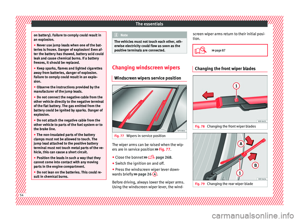
creen wipers service position Fig. 77
Wipers in service position The wiper arms can be raised when the wip-
er
s
ar
e in service position ››› Fig. 77.
● Close the bonnet ›››
page 268.
● Switch the ignition on and off.
● Press the windscreen wiper lever down-
ward
s briefly ››› page 26 4 .
B ef
or
e driving, always lower the wiper arms.
Using the windscreen wiper lever, the wind- screen wiper arms return to their initial posi-
tion.
››› page 87 Changing the front wiper blades
Fig. 78
Changing the front wiper blades Fig. 79
Changing the rear wiper blade54
Page 184 of 320

Operation
It flashes yellow
Steering column de-
viation.Gently turn the steering wheel to
and fro.
Steering wheel not
unlocked or locked.Remove the key from the ignition
and then switch the ignition
back on. Check the messages
displayed on the instrument
panel at the same time.
Do not drive on, if
the steering
column remains locked after the
ignition has been switched on.
Seek specialist assistance. Several warning and control lamps light up
f
or a f
ew sec
onds when the ignition is switch-
ed on, signalling that the function is being
verified. They will switch off after a few sec-
onds. WARNING
Observe the safety warnings ›››
in Control
and warnin g l
amps on page 105. Information on the steering
Steering column electronic lock
V
ehic
l
es with Keyless Access: the steering
column locks when the driver's door is
opened and the ignition is switched off.
Therefore, the vehicle should be at a stand-
still and, where applicable, the selector lever
in position P. If the driver door is opened before the igni-
tion is sw
itched off, the steering column elec-
tronic lock is activated via the ignition key or
the sensor built into the door handle.
Steering column mechanical lock
To prevent theft, we recommend you lock the
steering before leaving the vehicle.
Please engage steer-
ing lockUnlocking the steering
Parking the vehicle
››› page 187.Turn the steering wheel
slightly to release the
steering lock.
Remove the key from the
ignition.Insert the key in the igni-
tion lock.
Turn the steering wheel
slightly until you hear the
steering lock.Hold the steering wheel in
this position and switch
on the ignition. Electromechanical power steering
W
ith the po
w
er steering system, the assisted
steering function automatically adjusts ac-
cording to the vehicle speed, the steering tor-
que and the wheel turning angle. The power
steering only works when the engine is run-
ning.
You should remember that you will need con-
siderably more power than normal to steer
the vehicle if the power steering is not work-
ing correctly or not at all. Counter steering assistance system
The count
er steering assistance system helps
the driver in critical situations. Additional
steering power helps the driver when counter
steering. WARNING
The counter steering assistance system com-
bined w ith E
SC helps the driver to steer the
vehicle in critical driving conditions. At all
times, it is the driver who steers the vehicle.
The counter steering system does not steer
the vehicle. Stopping and starting the en-
gine
Intr oduction Immobiliser display
When an in
v
alid k
ey is used or in the event of
a system fault, or Immobiliser on is
displayed on the instrument panel. The en-
gine cannot be started.
Pushing or towing
For technical reasons, the vehicle must not
be push- or tow-started. Jump starting is pref-
erable.
182