Seat Alhambra 2018 Owner's Guide
Manufacturer: SEAT, Model Year: 2018, Model line: Alhambra, Model: Seat Alhambra 2018Pages: 324, PDF Size: 7.04 MB
Page 21 of 324
The essentials
Airbags Fr ont
Airb
agsFig. 25
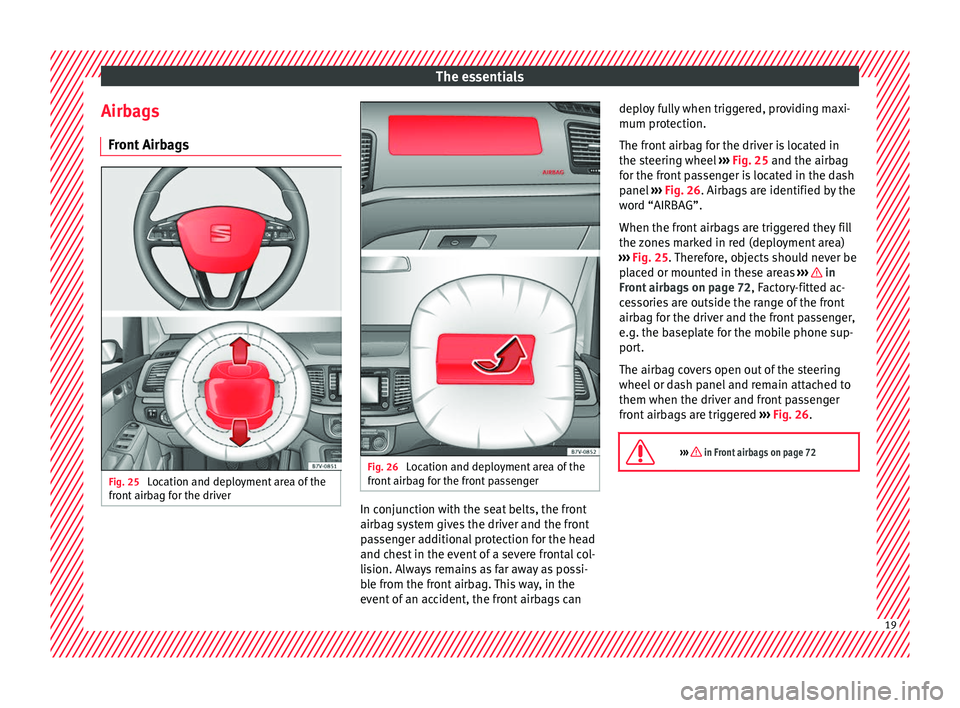
Location and deployment area of the
fr ont
airb
ag for the driver Fig. 26
Location and deployment area of the
fr ont
airb
ag for the front passenger In conjunction with the seat belts, the front
airb
ag sy
s
tem gives the driver and the front
passenger additional protection for the head
and chest in the event of a severe frontal col-
lision. Always remains as far away as possi-
ble from the front airbag. This way, in the
event of an accident, the front airbags can deploy fully when triggered, providing maxi-
mum protection.
The fr
ont airbag for the driver is located in
the steering wheel ››› Fig. 25 and the airbag
for the front passenger is located in the dash
panel ››› Fig. 26. Airbags are identified by the
word “AIRBAG”.
When the front airbags are triggered they fill
the zones marked in red (deployment area)
››› Fig. 25. Therefore, objects should never be
placed or mounted in these areas ››› in
Fr ont
airb
ags on page 72, Factory-fitted ac-
cessories are outside the range of the front
airbag for the driver and the front passenger,
e.g. the baseplate for the mobile phone sup-
port.
The airbag covers open out of the steering
wheel or dash panel and remain attached to
them when the driver and front passenger
front airbags are triggered ››› Fig. 26.
››› in Front airbags on page 72 19
Page 22 of 324
The essentials
Disconnecting the passenger front air-
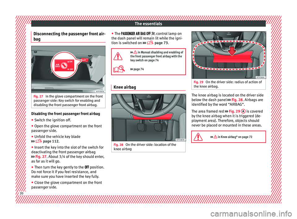
b ag Fig. 27
In the glove compartment on the front
p a
s
senger side: Key switch for enabling and
disabling the front passenger front airbag. Disabling the front passenger front airbag
● Switch the ignition off.
● Open the glove compartment on the front
p a
s
senger side.
● Unfold the vehicle key blade
›››
page 112.
● Insert the key into the slot of the switch for
deactivatin
g the front passenger airbag
››› Fig. 27. About 3/4 of the key should enter,
as far as it will go.
● Then turn the key gently to the position.
Do not
force it if you feel resistance, and
make sure you have inserted the key fully.
● Close the glove compartment on the front
pas
senger side. ●
The
control lamp on
the dash panel will remain lit while the igni-
tion is switched on ›››
page 73.
››› in Manual disabling and enabling of
the front passenger front airbag with the
key switch on page 74
››› page 74 Knee airbag
Fig. 28
On the driver side: location of the
knee airb ag Fig. 29
On the driver side: radius of action of
the knee airbag. The knee airbag is located on the driver side
belo
w the d
a
sh panel ››› Fig. 28. Airbags are
identified by the word “AIRBAG”.
The area framed red ››› Fig. 29 A is covered
b y
the knee airb
ag when it is triggered (de-
ployment area). Therefore, objects should
never be placed or mounted in these areas.
››› in Knee airbag* on page 72 20
Page 23 of 324
The essentials
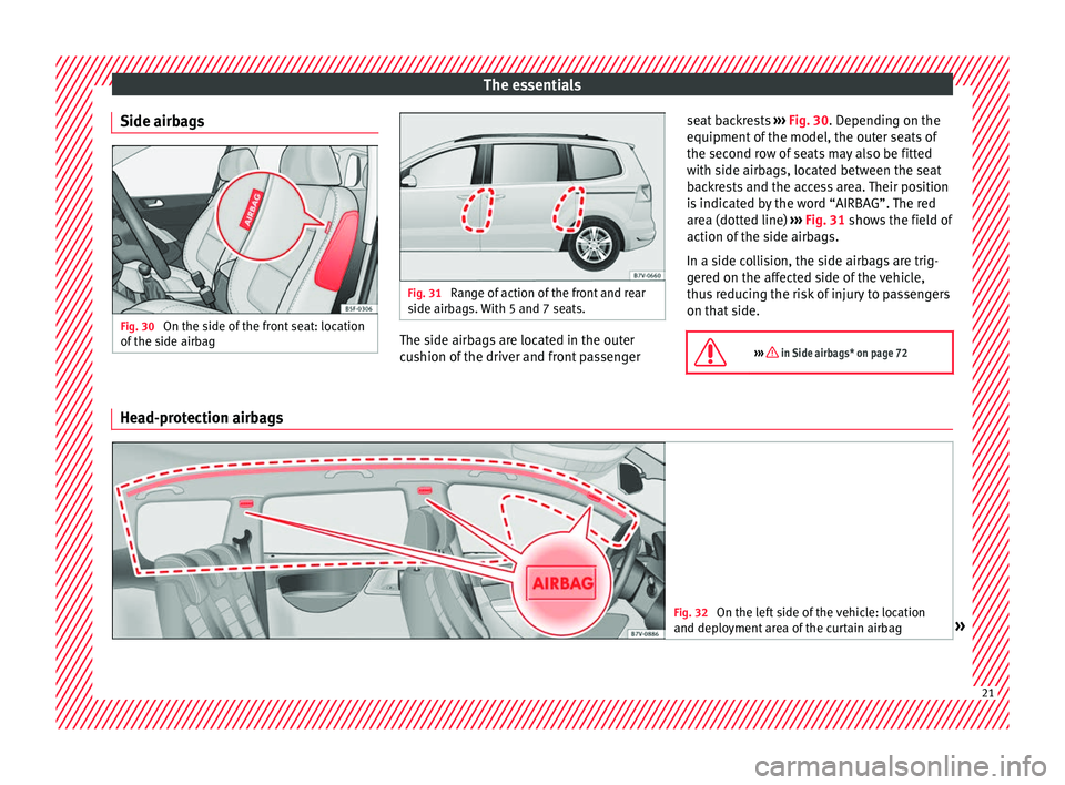
Side airbags Fig. 30
On the side of the front seat: location
of the s
ide airb
ag Fig. 31
Range of action of the front and rear
side airb ag
s. With 5 and 7 seats. The side airbags are located in the outer
c
u
shion of
the driver and front passenger seat backrests
›››
Fig. 30. Depending on the
equipment of the model, the outer seats of
the second row of seats may also be fitted
with side airbags, located between the seat
backrests and the access area. Their position
is indicated by the word “AIRBAG”. The red
area (dotted line) ››› Fig. 31 shows the field of
action of the side airbags.
In a side collision, the side airbags are trig-
gered on the affected side of the vehicle,
thus reducing the risk of injury to passengers
on that side.
››› in Side airbags* on page 72 Head-protection airbags
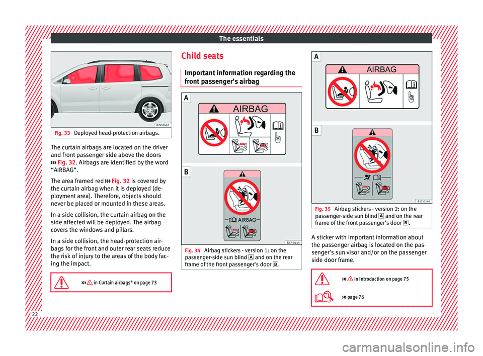
Fig. 32
On the left side of the vehicle: location
and deplo yment
area of the curtain airbag » 21
Page 24 of 324
The essentials
Fig. 33
Deployed head-protection airbags. The curtain airbags are located on the driver
and fr
ont
p
assenger side above the doors
››› Fig. 32. Airbags are identified by the word
“AIRBAG”.
The area framed red ››› Fig. 32 is covered by
the curtain airbag when it is deployed (de-
ployment area). Therefore, objects should
never be placed or mounted in these areas.
In a side collision, the curtain airbag on the
side affected will be deployed. The airbag
covers the windows and pillars.
In a side collision, the head-protection air-
bags for the front and outer rear seats reduce
the risk of injury to the areas of the body fac-
ing the impact.
››› in Curtain airbags* on page 73 Child seats
Impor t
ant
information regarding the
front passenger's airbag Fig. 34
Airbag stickers - version 1: on the
p a
s
senger-side sun blind and on the rear
frame of the front passenger's door . Fig. 35
Airbag stickers - version 2: on the
p a
s
senger-side sun blind and on the rear
frame of the front passenger's door . A sticker with important information about
the p
a
s
senger airbag is located on the pas-
senger's sun visor and/or on the passenger
side door frame.
››› in Introduction on page 75
››› page 76 22
Page 25 of 324
The essentials
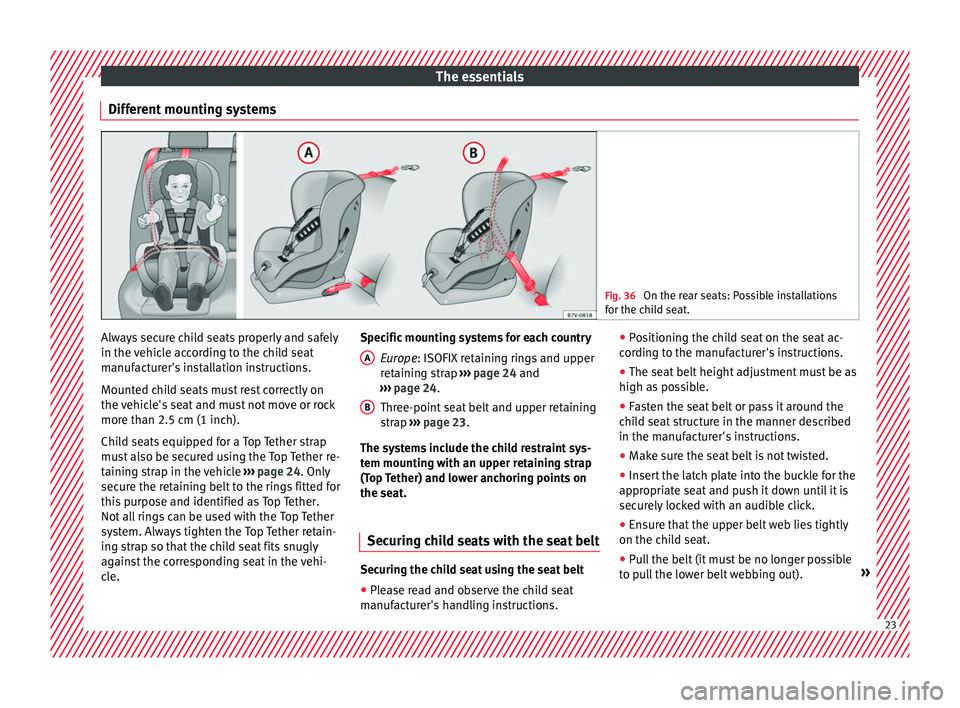
Different mounting systems Fig. 36
On the rear seats: Possible installations
for the c hi
ld seat. Always secure child seats properly and safely
in the
v
ehic
le according to the child seat
manufacturer's installation instructions.
Mounted child seats must rest correctly on
the vehicle's seat and must not move or rock
more than 2.5 cm (1 inch).
Child seats equipped for a Top Tether strap
must also be secured using the Top Tether re-
taining strap in the vehicle ››› page 24. Only
secure the retaining belt to the rings fitted for
this purpose and identified as Top Tether.
Not all rings can be used with the Top Tether
system. Always tighten the Top Tether retain-
ing strap so that the child seat fits snugly
against the corresponding seat in the vehi-
cle. Specific mounting systems for each country
Europe : ISOFIX retaining rings and upper
retaining strap ››› page 24 and
››› page 24.
Three-point seat belt and upper retaining
strap ››› page 23.
The systems include the child restraint sys-
tem mounting with an upper retaining strap
(Top Tether) and lower anchoring points on
the seat.
Securing child seats with the seat belt Securing the child seat using the seat belt
● Please read and observe the child seat
m anuf
act
urer's handling instructions.
A
B ●
Po
s
itioning the child seat on the seat ac-
cording to the manufacturer's instructions.
● The seat belt height adjustment must be as
high as po
ssible.
● Fasten the seat belt or pass it around the
chil
d seat structure in the manner described
in the manufacturer's instructions.
● Make sure the seat belt is not twisted.
● Insert the latch plate into the buckle for the
appropri
ate seat and push it down until it is
securely locked with an audible click.
● Ensure that the upper belt web lies tightly
on the chil
d seat.
● Pull the belt (it must be no longer possible
to pu
ll the lower belt webbing out). » 23
Page 26 of 324
The essentials
Removing the child seat
The se at
belt
must not be unfastened until
the vehicle has come to a standstill.
● Press the red button on the buckle. The
latc
h plate is released from the buckle.
● Guide the belt back by hand so that it rolls
up eas
ily and the trim will not be damaged.
● Remove the child seat from the vehicle.
››› in Safety instructions on page 76 Fix the child seat with the lower an-
c
hor point
s
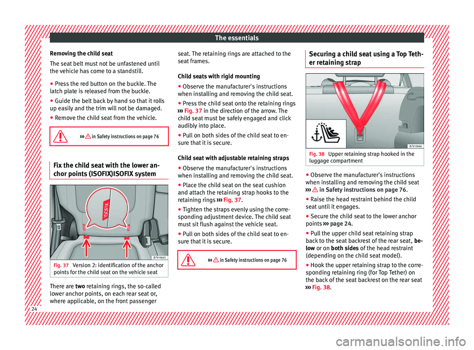
(ISOFIX)ISOFIX systemFig. 37
Version 2: identification of the anchor
points f
or the c
hild seat on the vehicle seat There are tw
o
r
etaining rings, the so-called
lower anchor points, on each rear seat or,
where applicable, on the front passenger seat. The retaining rings are attached to the
seat fr
ames.
Child seats with rigid mounting ● Observe the manufacturer's instructions
when inst
alling and removing the child seat.
● Press the child seat onto the retaining rings
›››
Fig. 37 in the direction of the arrow. The
child seat must be safely engaged and click
audibly into place.
● Pull on both sides of the child seat to en-
sure th
at it is secure.
Child seat with adjustable retaining straps
● Observe the manufacturer's instructions
when inst
alling and removing the child seat.
● Place the child seat on the seat cushion
and attach the r
etaining strap hooks to the
retaining rings ››› Fig. 37.
● Tighten the straps evenly using the corre-
sponding a
djustment device. The child seat
must sit flush against the vehicle seat.
● Pull on both sides of the child seat to en-
sure th
at it is secure.
››› in Safety instructions on page 76 Securing a child seat using a Top Teth-
er r
et
ainin
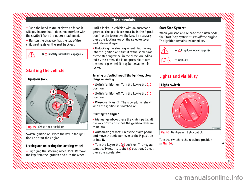
g strap Fig. 38
Upper retaining strap hooked in the
lug g
ag
e compartment ●
Observe the manufacturer's instructions
when in s
t
alling and removing the child seat
››› in Safety instructions on page 76.
● Raise the head restraint behind the child
se at
u
ntil it engages.
● Secure the child seat to the lower anchor
points ››
› page 24.
● Pull the upper child seat retaining strap
back
to the seat backrest of the rear seat, be-
low or on both sides of the head restraint
(depending on the child seat model).
● Hook the upper retaining strap to the corre-
sponding r
etaining ring (for Top Tether) on
the back of the seat backrest on the rear seat
››› Fig. 38.24
Page 27 of 324
The essentials
● Pu
sh the he
ad restraint down as far as it
will go. Ensure that it does not interfere with
the seatbelt from the upper attachment.
● Tighten the strap so that the top of the
chil
d seat rests on the seat backrest.
››› in Safety instructions on page 76 Starting the vehicle
Ignition lock Fig. 39
Vehicle key positions Switch ignition on: Place the key in the igni-
tion and s
t
ar
t the engine.
Locking and unlocking the steering wheel
● Engaging the steering wheel lock: Remove
the key fr
om the ignition and turn the wheel until it locks. In vehicles with an automatic
gearbo
x, the gear lever must be in the P posi-
tion in order to remove the key. If necessary,
press the locking key on the selector lever
and release it again.
● Unlocking the steering wheel: Put the key
into the ignition and turn it
at the same time
as the steering wheel in the direction indica-
ted by the arrow. If it is not possible to turn
the steering wheel, it may be because it is
locked.
Turning on/switching off the ignition, glow
plugs reheating
● Switch ignition on: Turn the key to the 2 position.
●
Switch ignition off. Turn the key to the 1 position.
●
Diesel vehicles : The glo
w p
lugs reheat
when the ignition is switched on.
Starting the engine
● Manual gearbox: press the clutch pedal all
the way
down and move the gearbox lever in-
to neutral.
● Automatic gearbox: Press the brake pedal
and move the sel
ector lever to the P position
or into N.
● Turn the key to the 3 position. The key au-
t om
atic
ally returns to the 2 position. Do not
pr e
s
s the accelerator. Start-Stop System*
When you s
top and release the clutch pedal,
the Start-Stop system* turns off the engine.
The ignition remains switched on.
››› in Ignition lock on page 184
››› page 184 Lights and visibility
Light sw
it
ch Fig. 40
Dash panel: light control. Turn the switch to the required position
› ›
›
Fig. 40. » 25
Page 28 of 324
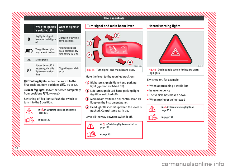
The essentials When the ignition
is switched offWhen the ignition
is on
Fog lights, dipped
beam and side lights
off.Lights off or daytime
driving light on.
The guidance lights
may be switched on.Automatic dipped
beam control or day-
time driving light on.
Side light on.
Dipped beam off; if
necessary, the side
light comes on for a
time.Dipped beam switch-
ed on.
Front
fog lights: mo
ve the switch to the
first position, from positions , or .
Rear fog light: move the switch completely
from positions , or .
Switching off fog lights: Push the switch or
turn it to the position.
››› in Switching lights on and off on
page 131
››› page 130 Turn signal and main beam lever
Fig. 41
Turn signal and main beam lever. More the lever to the required position:
Right t
urn s
ignal: Right-hand parking
light (ignition switched off).
Left turn signal: Left-hand parking light
(ignition switched off).
Main beam switched on: control lamp
lit up on the instrument panel.
Headlight flasher: lit up when the lever is
pushed. Control lamp lit up.
Lever all the way down to switch it off.
››› in Switching lights on and off on
page 131
››› page 131 1
2
3
4 Hazard warning lights
Fig. 42
Dash panel: switch for hazard warn-
in g lights. Switched on, for example:
●
When approaching a traffic jam
● In an emergency
● The vehicle has broken down
● When towing or being towed
››› in Hazard warning lights on
page 135
››› page 134 26
Page 29 of 324
The essentials
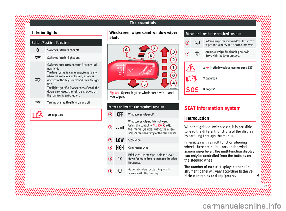
Interior lightsButton/Position: Function
Switches interior lights off.
Switches interior lights on.
Switches door contact control on (central
position).
The interior lights come on automatically
when the vehicle is unlocked, a door is
opened or the key is removed from the igni-
tion.
The lights go off a few seconds after all the
doors are closed, the vehicle is locked or
the ignition is switched on.
Turning the reading light on and off
›››
page 136 Windscreen wipers and window wiper
b
l
a
de Fig. 43
Operating the windscreen wiper and
r e
ar w
iper.
Move the lever to the required position
0 Windscreen wiper off.
1
Windscreen wipers interval wipe.
Using the control
››› Fig. 43 A adjust
the interval (vehicles without rain sen-
sor), or the sensitivity of the rain sensor.
2 Slow wipe.
3
Continuous wipe.
4
Brief wipe - short wipe. Hold the lever
down for more time to increase the wipe
frequency.
5
Automatic wipe for cleaning wind-
screens with the lever up.
Move the lever to the required position
6 Interval wipe for rear window. The wiper
wipes the window at 6-second intervals.
7
Automatic wipe for cleaning rear win-
dows with the lever pressed.
››› in Window wiper lever on page 137
›››
page 137
››› page 55 SEAT information system
Intr oduction With the ignition switched on, it is possible
t
o r
e
ad the different functions of the display
by scrolling through the menus.
In vehicles with a multifunction steering
wheel, there are no buttons on the wind-
screen wiper lever. The multifunction display
can only be controlled from the buttons on
the steering wheel.
The number of menus displayed on the in-
strument panel will vary according to the ve-
hicle electronics and equipment. » 27
Page 30 of 324
The essentials
A specialised workshop will be able to pro-
gr amme or modif
y
additional functions, ac-
cording to the vehicle equipment. SEAT rec-
ommends taking your car in for technical
service.
Some menu options can only be read when
the vehicle is at a standstill.
As long as a priority 1 warning is displayed, it
will not be possible to read the menus. To
display the menus, confirm the warning by
pressing OK .
Summary of the menu structure ■
Mu ltif
unction display (MFD) ››› page 30
■ Travelling time
■ Current fuel consumption
■ Average fuel consumption
■ Operating range
■ Distance covered
■ Average speed
■ Digital display of speed
■ Oil temperature digital display
■ Speed warning
■ Audio ›››
Booklet Radio or ›››
Booklet Navi-
gation system
■ Navigation ›››
Booklet Navigation system
■ Telephone ›››
Booklet Radio or ›››
Booklet
Navigation system
■ Auxiliary heating ›››
page 180 ■
Activ ation
■ Pr
ogramme On / Off
■ Disconnection
■ Timer 1-3
■ Day
■ Time
■ Minute
■ Activate
■ Duration
■ Operating mode
■ Heat
■ Ventilation
■ Day
■ Default setting
■ Vehicle condition ››› page 29
■ Configuration ››› page 31
■ Multifunction display data
■ Travelling time
■ Current fuel consumption
■ Average fuel consumption
■ Distance covered
■ Operating range
■ Average speed
■ Digital display of speed
■ Speed warning
■ Compass
■ Convenience ››› page 32
■ Central locking system (Central locking)
■Automatic lock (Auto. lock) On / Off ■
Automatic unlocking (Auto. unlock.)
On / Off
■ Unlocking doors (Door unlock.: All,
One door, Vehicle side, Individual)
■ Back
■ Electric windows
■ Off
■ All
■ Driver
■ Back
■ Mirror angle (Mirror angle) On / Off
■ Adjusting mirrors (Adjust. mirrors)
■ Individual
■ Synchronised
■ Back
■ Factory settings (Factory settings)
■ Back
■ Lights & visibility ››› page 32
■ Coming Home
■ Leaving Home
■ Footwell light
■ Convenience turn signals On / Off
■ Default setting
■ Tourist light On / Off
■ Time
■ Winter tyres
■ Language
■ Units
■ Second speed display On / Off 28