Seat Altea XL 2015 Owner's Guide
Manufacturer: SEAT, Model Year: 2015, Model line: Altea XL, Model: Seat Altea XL 2015Pages: 236, PDF Size: 4.23 MB
Page 31 of 236
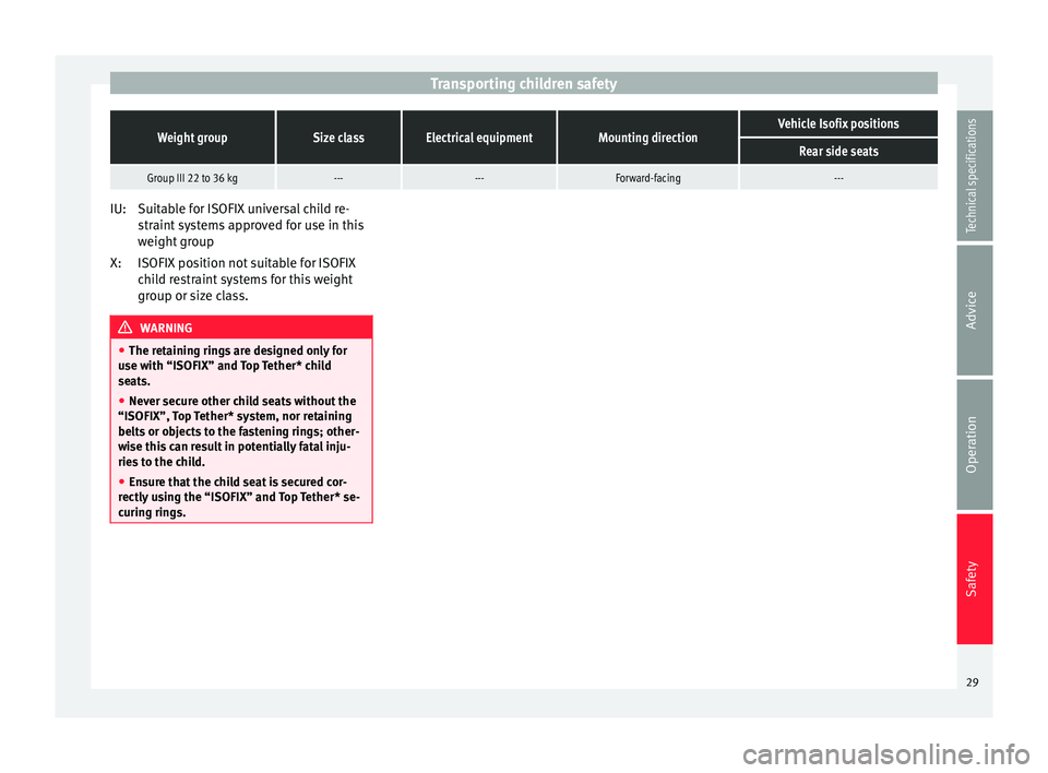
Transporting children safetyWeight groupSize classElectrical equipmentMounting directionVehicle Isofix positions
Rear side seats
Group III 22 to 36 kg------Forward-facing---
Suitable for ISOFIX universal child re-
straint systems approved for use in this
weight group
ISOFIX position not suitable for ISOFIX
child restraint systems for this weight
group or size class.
WARNING
● The retaining rings are designed only for
use with “ISOFIX” and Top Tether* child
seats.
● Never secure other child seats without the
“ISOFIX”, Top Tether* system, nor retaining
belts or objects to the fastening rings; other-
wise this can result in potentially fatal inju-
ries to the child.
● Ensure that the child seat is secured cor-
rectly using the “ISOFIX” and Top Tether* se-
curing rings. IU:
X:
29
Technical specifications
Advice
Operation
Safety
Page 32 of 236
Operation
Fig. 25
Dash panel.30
Page 33 of 236
Dash panel
Operation
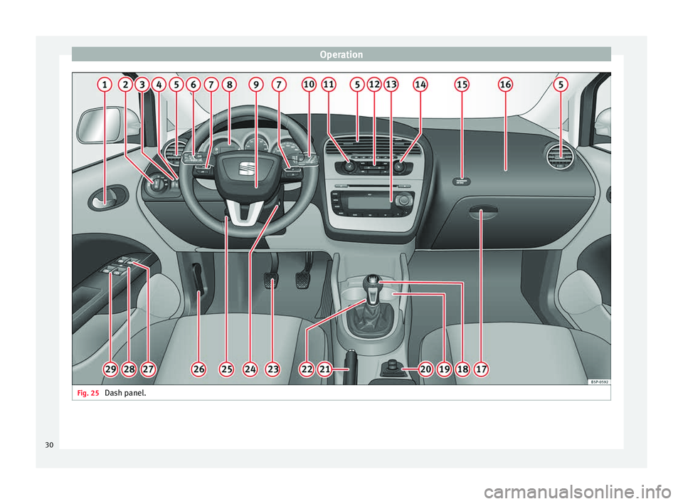
Dash panel Overview Overview of the dash panel Door release lever
Light switch
. . . . . . . . . . . . . . . . . . . . . . 75
Lighting control for instrument and
switch lighting. . . . . . . . . . . . . . . . . . . . 79
Headlight range control . . . . . . . . . . .79
Air vents
Turn signal and main beam lever
and cruise control system* . . . . . . . .77, 142
Controls on the steering wheel . . . .57
Instrument panel:
– Instruments . . . . . . . . . . . . . . . . . . . . 32
– Display . . . . . . . . . . . . . . . . . . . . . . . . . 47
– Control and warning lamps . . . . . .35
1 2
3
4
5
6
7
8 Horn (works only when the ignition
is on)/ Driver front airbag
. . . . . . . . .17
Windscreen wiper lever and opera-
tion of the multi-function display* .84, 52
Left seat heating button . . . . . . . . . .91
Controls for
– Heating* and ventilation . . . . . . . .107
– Climatic* . . . . . . . . . . . . . . . . . . . . . . . 109
– Climatronic* . . . . . . . . . . . . . . . . . . . . 112
Radio/Navigator*
Right seat heating button . . . . . . . . .91
Control lamp for front passenger
airbag deactivated warning lamp . .23
Front passenger front airbag . . . . . .17
Glove compartment lever . . . . . . . . .93
Selector lever . . . . . . . . . . . . . . . . . . . . 127
Cup holder compartment . . . . . . . . .95
Controls in the centre console: – Central locking . . . . . . . . . . . . . . . . . 63
– ESC . . . . . . . . . . . . . . . . . . . . . . . . . . . . 134
9 10
11
12
13
14
15
16
17
18
19
20 –
Tyre pressure control* . . . . . . . . . . .43
– Park Pilot* . . . . . . . . . . . . . . . . . . . . . . 140
– Cigarette lighter/Power socket . .98
– Exterior mirror adjustment . . . . . .87
– Start-Stop* . . . . . . . . . . . . . . . . . . . . . 138
Handbrake . . . . . . . . . . . . . . . . . . . . . . . 123
Hazard warning lights switch . . . . . .81
Pedals
Ignition lock . . . . . . . . . . . . . . . . . . . . . . 120
Steering column control lever* . . . .7
Handle for releasing the bonnet . . .163
Button for opening and closing the
front windows . . . . . . . . . . . . . . . . . . . . 72
Safety switch* for the rear windows . . .72
Control* for opening and closing
the rear windows . . . . . . . . . . . . . . . . . 72 Note
Some of the items of equipment listed here
are fitted only on certain model versions or
are optional extras. 21
22
23
24
25
26
27
28
29
31Technical specifications
Advice
Operation
Safety
Page 34 of 236
Operation
Instruments Instrument overview Fig. 26
Detailed view of the dash panel: Dash
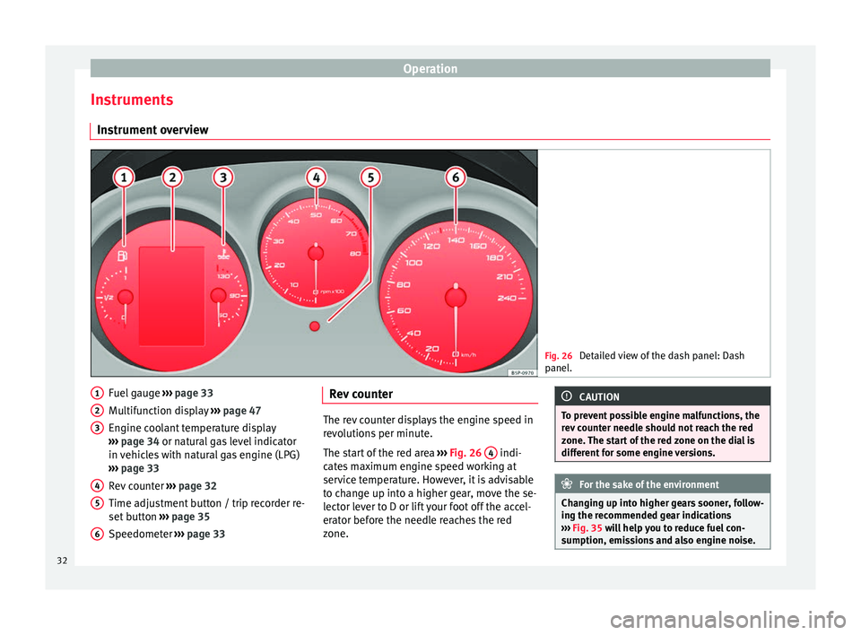
panel. Fuel gauge
››› page 33
Multifunction display ››› page 47
Engine coolant temperature display
››› page 34 or natural gas level indicator
in v
ehicles with natural gas engine (LPG)
››› page 33
Rev counter ››› page 32
Time adjustment button / trip recorder re-
set button ››› page 35
Speedometer ››› page 33
1 2
3
4
5
6 Rev counter
The rev counter displays the engine speed in
revolutions per minute.
The start of the red area
››› Fig. 26 4 indi-
cates maximum engine speed working at
service temperature. However, it is advisable
to change up into a higher gear, move the se-
lector lever to D or lift your foot off the accel-
erator before the needle reaches the red
zone. CAUTION
To prevent possible engine malfunctions, the
rev counter needle should not reach the red
zone. The start of the red zone on the dial is
different for some engine versions. For the sake of the environment
Changing up into higher gears sooner, follow-
ing the recommended gear indications
››› Fig. 35 will help you to reduce fuel con-
s umption, emi
ssions and also engine noise.32
Page 35 of 236
Dash panel
Speedometer The speedometer is equipped with a digital
odometer and a trip odometer, in addition to
a service intervals display.
During the running-in period, the instructions
shown on
››› page 130 should be followed.
F uel
gauge and reserve indicator Fig. 27
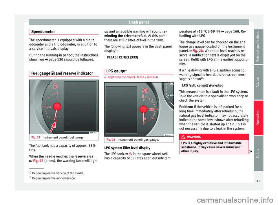
Instrument panel: fuel gauge The fuel tank has a capacity of approx. 55 li-
tres.
When the needle reaches the reserve area
››› Fig. 27 (arrow), the warning lamp will light up and an audib
l
e warning will sound
re-
minding the driver to refuel. At this point
there are still 7 litres of fuel in the tank.
The following text appears in the dash panel
display 1)
:
PLEASE REFUEL [XXX]
LPG gauge* 3 Applies to the model: ALTEA / ALTEA XL
Fig. 28
Instrument panel: gas gauge. LPG system filler level display
The LPG tank
››› in the spare wheel well
has a capacity of 39 litres at an outside tem- perature of +15 °C (+59 °F)
››› page 160, Re-
fuelling with LPG .
The c h
arge level can be checked on the ana-
logue gas gauge located on the instrument
panel ››› Fig. 28. When the level reaches re-
serv
e, a notification text is displayed on the
screen. Refill with LPG at the earliest opportu-
nity.
If while driving with LPG a sudden acoustic
warning signal is heard, the on-screen mes-
sage is shown 2)
:
LPG fault, consult Workshop
This means there is a fault in the LPG system.
Take the vehicle to a specialised workshop to
check the system.
Problem: If the vehicle is left parked for a
long time immedi
ately after refuelling, the
natural gas level indicator may not accurately
indicate the same level shown after refuelling
when the vehicle is started up again. This is
not necessarily due to a leak in the system. WARNING
LPG is a highly explosive and inflammable
substance. It may cause severe burns and
other injury. »1)
Depending on the version of the model.
2) Depending on the model version
33
Technical specifications
Advice
Operation
Safety
Page 36 of 236
Operation
●
Due care must be taken to avoid any risk of
fire or explosion.
● When parking the vehicle in a closed area
(e.g. in a garage), make sure that there is ad-
equate ventilation, either natural or mechani-
cal, to neutralise the LPG in the event of a
leak. Note
● The values shown in the average fuel con-
sumption and distance to empty indications
on the multifunction display (MFI) 1)
on the in-
strument panel display 2)
are approximate val-
ues only.
● Two different consumption values are given
on the MFI, depending on whether the vehi-
cle is running in gas or petrol mode.
● Please check the fuel level on the fuel level
gauge on the instrument panel ››› page 33.
● If frequent short journeys are made, espe-
cially when the outside temperature is low,
the vehicle will tend to run on petrol more of-
ten than on LPG. Therefore, the petrol tank
may empty before the LPG tank. Engine coolant temperature gauge
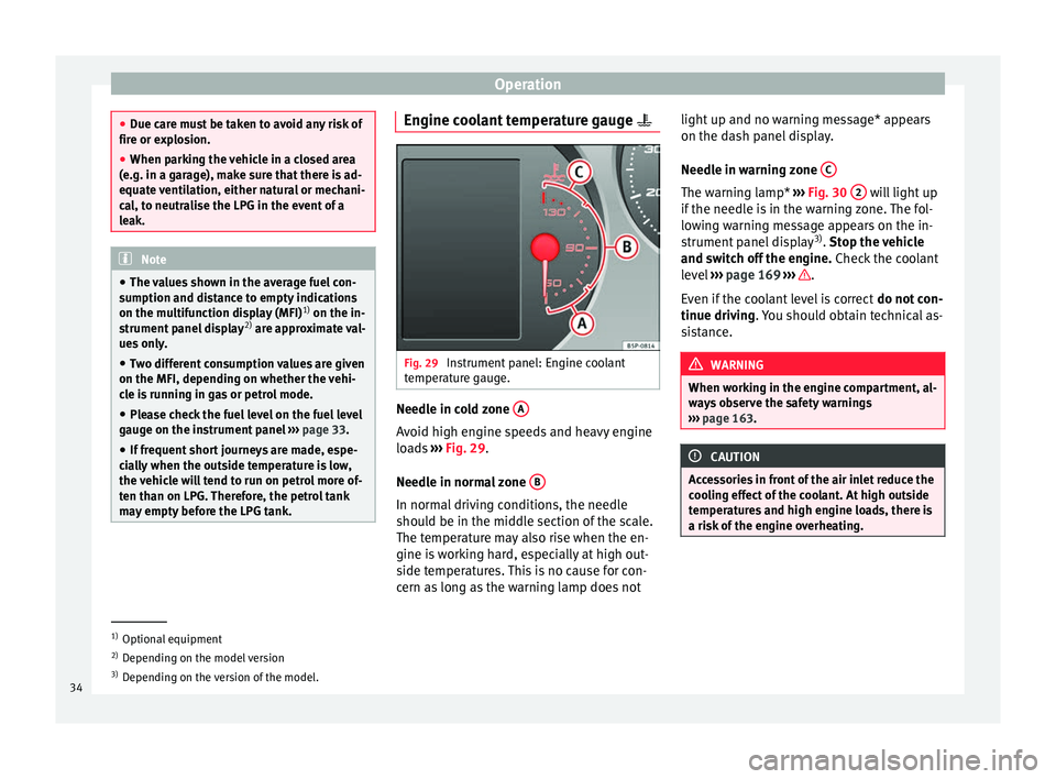
Fig. 29
Instrument panel: Engine coolant
temperature gauge. Needle in cold zone
A Avoid high engine speeds and heavy engine
loads
››› Fig. 29 .
Needl e in norm
al zone B In normal driving conditions, the needle
should be in the middle section of the scale.
The temperature may also rise when the en-
gine is working hard, especially at high out-
side temperatures. This is no cause for con-
cern as long as the warning lamp does notlight up and no warning message* appears
on the dash panel display.
Needle in warning zone
C The warning lamp*
››› Fig. 30 2 will light up
if the needle is in the warning zone. The fol-
lowing warning message appears on the in-
strument panel display 3)
. Stop the vehicle
and sw it
ch off the engine. Check the coolant
level ››› page 169 ››› .
Even if the coolant level is correct do not con-
tinue driving . You should obtain technical as-
s i
stance. WARNING
When working in the engine compartment, al-
ways observe the safety warnings
››› page 163. CAUTION
Accessories in front of the air inlet reduce the
cooling effect of the coolant. At high outside
temperatures and high engine loads, there is
a risk of the engine overheating. 1)
Optional equipment
2) Depending on the model version
3) Depending on the version of the model.
34
Page 37 of 236
Dash panel
Setting the digital clock* The digital clock is located in the instrument
panel display.
–
Turn the setting knob ››› Fig. 26
5 clock-
wise until the first “click” to set the hour.
The hour will flash. To change the hour,
press the button. –
Turn the setting knob clockwise to the sec-
ond “click” to set the minutes. The minutes
will flash. To change the minutes, press the
button.
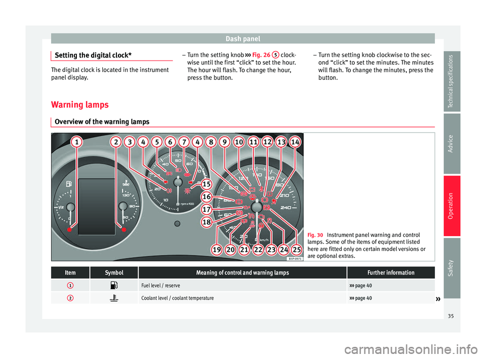
Warning lamps Overview of the warning lamps Fig. 30
Instrument panel warning and control
lamps. Some of the items of equipment listed
here are fitted only on certain model versions or
are optional extras.ItemSymbolMeaning of control and warning lampsFurther information
1 Fuel level / reserve›››
page 40
2 Coolant level / coolant temperature›››
page 40» 35
Technical specifications
Advice
Operation
Safety
Page 38 of 236
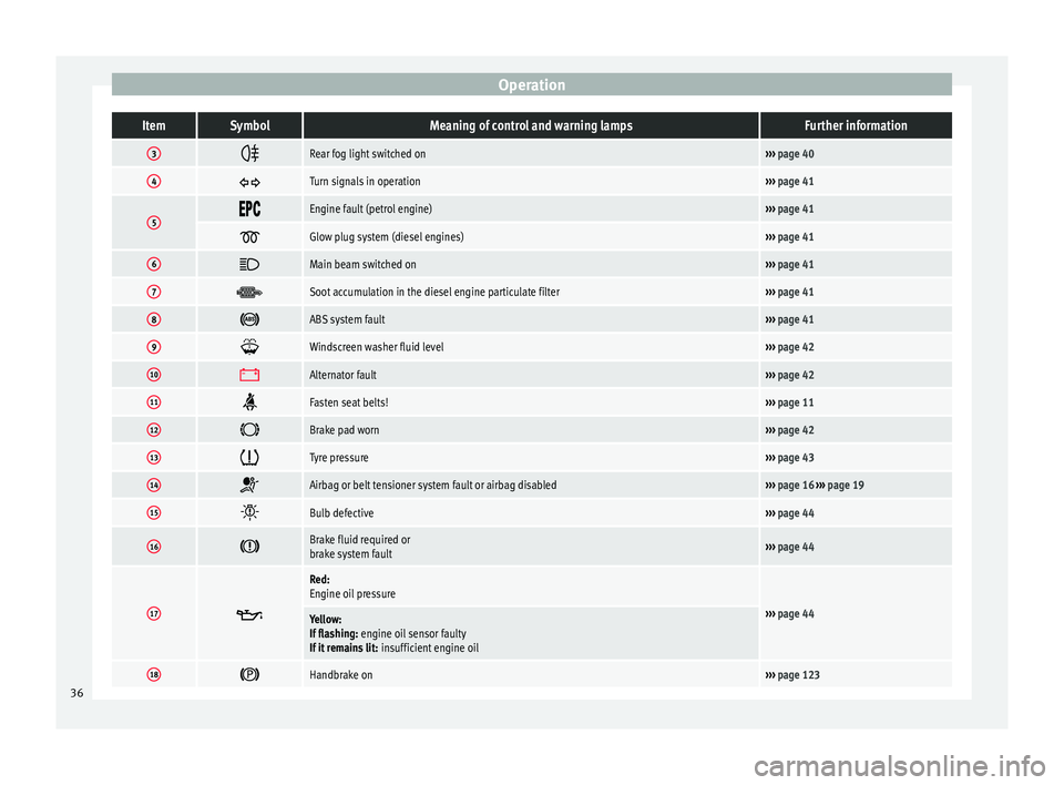
OperationItemSymbolMeaning of control and warning lampsFurther information
3
Rear fog light switched on›››
page 40
4 Turn signals in operation›››
page 41
5 Engine fault (petrol engine)›››
page 41
Glow plug system (diesel engines)›››
page 41
6 Main beam switched on›››
page 41
7 Soot accumulation in the diesel engine particulate filter›››
page 41
8 ABS system fault›››
page 41
9 Windscreen washer fluid level›››
page 42
10 Alternator fault›››
page 42
11 Fasten seat belts!›››
page 11
12 Brake pad worn›››
page 42
13 Tyre pressure›››
page 43
14 Airbag or belt tensioner system fault or airbag disabled›››
page 16 ››› page 19
15 Bulb defective›››
page 44
16 Brake fluid required or
brake system fault›››
page 44
17
Red:
Engine oil pressure
›››
page 44Yellow:
If flashing: engine oil sensor faulty
If it remains lit: insufficient engine oil
18 Handbrake on›››
page 123 36
Page 39 of 236
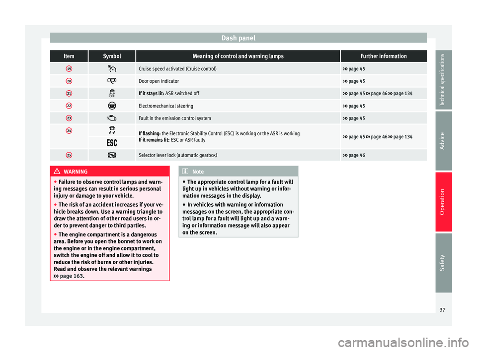
Dash panelItemSymbolMeaning of control and warning lampsFurther information
19
Cruise speed activated (Cruise control)›››
page 45
20 Door open indicator›››
page 45
21 If it stays lit:
ASR switched off››› page 45 ››› page 46 ››› page 134
22 Electromechanical steering›››
page 45
23 Fault in the emission control system›››
page 45
24 If flashing:
the Electronic Stability Control (ESC) is working or the ASR is working
If it remains lit: ESC or ASR faulty››› page 45 ››› page 46 ››› page 134
25
Selector lever lock (automatic gearbox)›››
page 46 WARNING
● Failure to observe control lamps and warn-
ing messages can result in serious personal
injury or damage to your vehicle.
● The risk of an accident increases if your ve-
hicle breaks down. Use a warning triangle to
draw the attention of other road users in or-
der to prevent danger to third parties.
● The engine compartment is a dangerous
area. Before you open the bonnet to work on
the engine or in the engine compartment,
switch the engine off and allow it to cool to
reduce the risk of burns or other injuries.
Read and observe the relevant warnings
››› page 163. Note
● The appropriate control lamp for a fault will
light up in vehicles without warning or infor-
mation messages in the display.
● In vehicles with warning or information
messages on the screen, the appropriate con-
trol lamp for a fault will light up and a warn-
ing or information message will also appear
on the screen. 37
Technical specifications
Advice
Operation
Safety
Page 40 of 236
Operation
Overview of control and warning
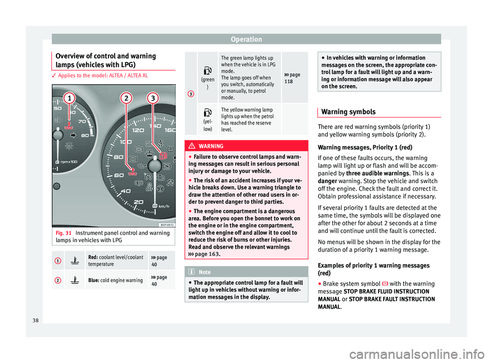
lamps (vehicles with LPG) 3 Applies to the model: ALTEA / ALTEA XL
Fig. 31
Instrument panel control and warning
lamps in vehicles with LPG1 Red: coolant level/coolant
temperature›››
page
40
2 Blue: cold engine warning›››
page
40
3
(green
)
The green lamp lights up
when the vehicle is in LPG
mode.
The lamp goes off when
you switch, automatically
or manually, to petrol
mode.
››› page
118
(yel-
low)
The yellow warning lamp
lights up when the petrol
has reached the reserve
level.
WARNING
● Failure to observe control lamps and warn-
ing messages can result in serious personal
injury or damage to your vehicle.
● The risk of an accident increases if your ve-
hicle breaks down. Use a warning triangle to
draw the attention of other road users in or-
der to prevent danger to third parties.
● The engine compartment is a dangerous
area. Before you open the bonnet to work on
the engine or in the engine compartment,
switch the engine off and allow it to cool to
reduce the risk of burns or other injuries.
Read and observe the relevant warnings
››› page 163. Note
● The appropriate control lamp for a fault will
light up in vehicles without warning or infor-
mation messages in the display. ●
In vehicles with warning or information
messages on the screen, the appropriate con-
trol lamp for a fault will light up and a warn-
ing or information message will also appear
on the screen. Warning symbols
There are red warning symbols (priority 1)
and yellow warning symbols (priority 2).
Warning messages, Priority 1 (red)
If one of these faults occurs, the warning
lamp will light up or flash and will be accom-
panied by
three audible warnings. This is a
danger warning. Stop the vehicle and switch
off the en
gine. Check the fault and correct it.
Obtain professional assistance if necessary.
If several priority 1 faults are detected at the
same time, the symbols will be displayed one
after the other for about 2 seconds at a time
and will continue until the fault is corrected.
No menus will be shown in the display for the
duration of a priority 1 warning message.
Examples of priority 1 warning messages
(red)
● Brake system symbol with the warning
message STOP BRAKE FLUID INSTRUCTION
MANUAL or STOP BRAKE FAULT INSTRUCTION MANUAL.
38