Seat Arona 2017 Owner's Guide
Manufacturer: SEAT, Model Year: 2017, Model line: Arona, Model: Seat Arona 2017Pages: 308, PDF Size: 6.66 MB
Page 21 of 308
The essentials
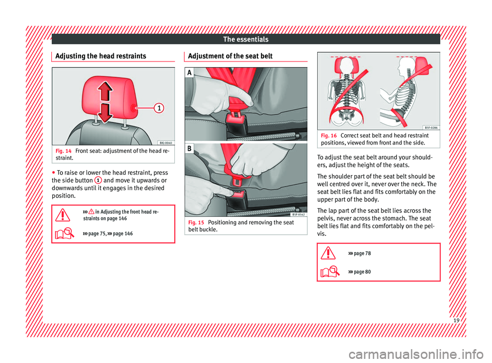
Adjusting the head restraints Fig. 14
Front seat: adjustment of the head re-
s tr
aint
. ●
To raise or lower the head restraint, press
the s ide b
utt
on 1 and move it upwards or
do wn
w
ards until it engages in the desired
position.
››› in Adjusting the front head re-
straints on page 146
››› page 75, ››› page 146 Adjustment of the seat belt
Fig. 15
Positioning and removing the seat
belt b
uc
kle. Fig. 16
Correct seat belt and head restraint
pos ition
s, viewed from front and the side. To adjust the seat belt around your should-
er
s, a
dju
st the height of the seats.
The shoulder part of the seat belt should be
well centred over it, never over the neck. The
seat belt lies flat and fits comfortably on the
upper part of the body.
The lap part of the seat belt lies across the
pelvis, never across the stomach. The seat
belt lies flat and fits comfortably on the pel-
vis.
››› page 78
››› page 80 19
Page 22 of 308
The essentials
Seat belt tensioners During a collision, the seat belts on the front
seats
ar
e retracted automatically.
The tensioner can be triggered only once.
››› in Service and disposal of belt ten-
sioners on page 82
››› page 81 Adjusting the exterior mirrors
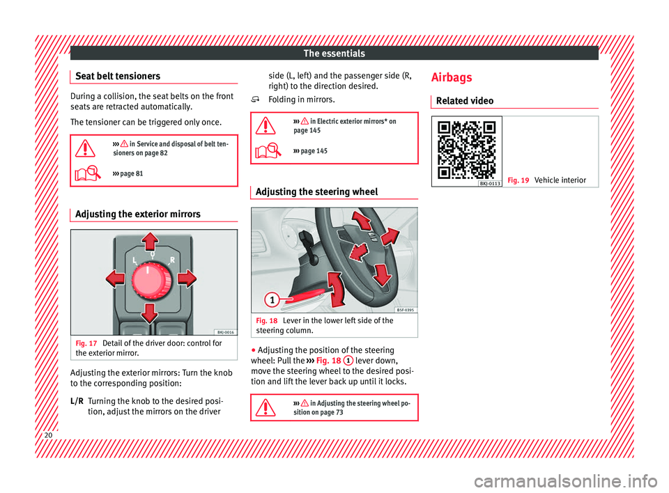
Fig. 17
Detail of the driver door: control for
the e xt
erior mirr
or. Adjusting the exterior mirrors: Turn the knob
t
o the c
orr
esponding position:
Turning the knob to the desired posi-
tion, adjust the mirrors on the driver
L/R side (L, left) and the passenger side (R,
right) to the direction de
sired.
Folding in mirrors.
››› in Electric exterior mirrors* on
page 145
››› page 145 Adjusting the steering wheel
Fig. 18
Lever in the lower left side of the
s t
eerin
g column. ●
Adjusting the position of the steering
wheel: P ul
l the ››› Fig. 18 1 lever down,
mo v
e the s
teering wheel to the desired posi-
tion and lift the lever back up until it locks.
››› in Adjusting the steering wheel po-
sition on page 73
Airbags
R el
at
ed video Fig. 19
Vehicle interior20
Page 23 of 308
The essentials
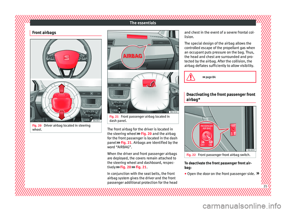
Front airbags Fig. 20
Driver airbag located in steering
wheel . Fig. 21
Front passenger airbag located in
d ash p
anel. The front airbag for the driver is located in
the s
t
eerin
g wheel ››› Fig. 20 and the airbag
for the front passenger is located in the dash
panel ››› Fig. 21. Airbags are identified by the
word “AIRBAG”.
When the driver and front passenger airbags
are deployed, the covers remain attached to
the steering wheel and dashboard, respec-
tively ››› Fig. 20 ››› Fig. 21.
In conjunction with the seat belts, the front
airbag system gives the driver and the front
passenger additional protection for the head and chest in the event of a severe frontal col-
lision.
The s
pecial design of the airbag allows the
controlled escape of the propellant gas when
an occupant puts pressure on the bag. Thus,
the head and chest are surrounded and pro-
tected by the airbag. After the collision, the
airbag deflates sufficiently to allow visibility.
››› page 84 Deactivating the front passenger front
airb
ag* Fig. 22
Front passenger front airbag switch. To deactivate the front passenger front air-
b
ag:
● Open the door on the fr ont
passenger side.» 21
Page 24 of 308
The essentials
● Inser
t
the key blade into the slot provided
in the deactivation switch.
● Approximately ¾ of the length of the key
bla
de remains inserted (the maximum).
● Turn the key blade, changing its position to
. Do not for
ce it. If you have difficulty, en-
sure that you have inserted the key as far as
it will go.
● Finally, check the control lamp on the in-
strument p
anel where it shows
the following should appear .
››› in Deactivation of front passenger
front airbag* on page 87
››› page 86 Side airbags*
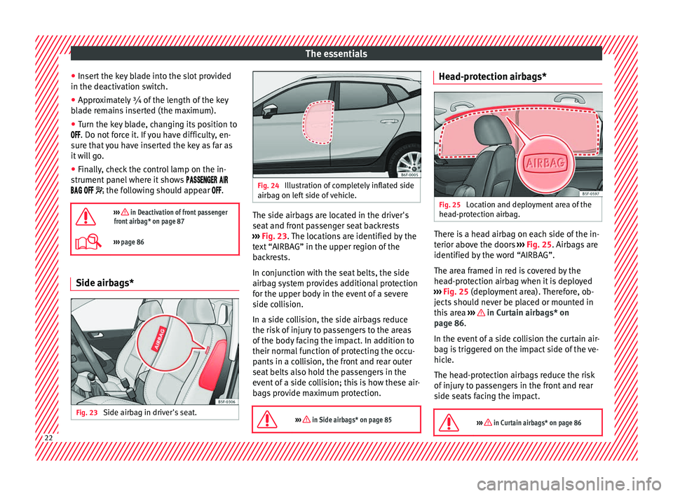
Fig. 23
Side airbag in driver's seat. Fig. 24
Illustration of completely inflated side
airbag on l ef
t side of vehicle. The side airbags are located in the driver's
se
at
and fr
ont passenger seat backrests
››› Fig. 23. The locations are identified by the
text “AIRBAG” in the upper region of the
backrests.
In conjunction with the seat belts, the side
airbag system provides additional protection
for the upper body in the event of a severe
side collision.
In a side collision, the side airbags reduce
the risk of injury to passengers to the areas
of the body facing the impact. In addition to
their normal function of protecting the occu-
pants in a collision, the front and rear outer
seat belts also hold the passengers in the
event of a side collision; this is how these air-
bags provide maximum protection.
››› in Side airbags* on page 85 Head-protection airbags*
Fig. 25
Location and deployment area of the
he a
d-pr
otection airbag. There is a head airbag on each side of the in-
t
erior abo
v
e the doors ››› Fig. 25. Airbags are
identified by the word “AIRBAG”.
The area framed in red is covered by the
head-protection airbag when it is deployed
››› Fig. 25 (deployment area). Therefore, ob-
jects should never be placed or mounted in
this area ››› in Curtain airbags* on
p ag
e 86
.
In the event of a side collision the curtain air-
bag is triggered on the impact side of the ve-
hicle.
The head-protection airbags reduce the risk
of injury to passengers in the front and rear
side seats facing the impact.
››› in Curtain airbags* on page 86 22
Page 25 of 308
The essentials
Child seats R el
at
ed video Fig. 26
Vehicle interior Important information regarding the
fr
ont
p
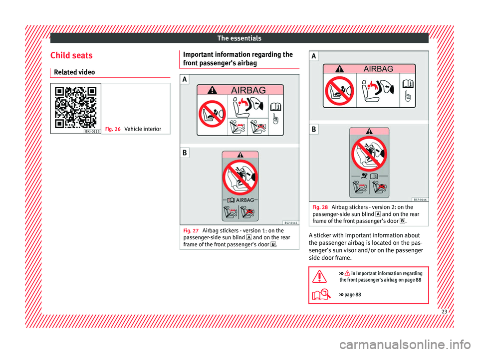
assenger's airbag Fig. 27
Airbag stickers - version 1: on the
p a
s
senger-side sun blind and on the rear
frame of the front passenger's door . Fig. 28
Airbag stickers - version 2: on the
p a
s
senger-side sun blind and on the rear
frame of the front passenger's door . A sticker with important information about
the p
a
s
senger airbag is located on the pas-
senger's sun visor and/or on the passenger
side door frame.
››› in Important information regarding
the front passenger's airbag on page 88
››› page 88 23
Page 26 of 308
The essentials
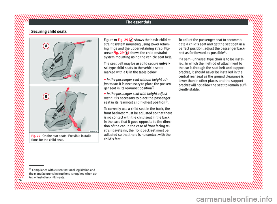
Securing child seats Fig. 29
On the rear seats: Possible installa-
tions f
or the child seat. Figure
››› Fig. 29 A shows the basic child re-
str aint
system mounting using lower retain-
ing rings and the upper retaining strap. Fig-
ure ››› Fig. 29 B shows the child restraint
sys t
em mounting using the vehicle seat belt.
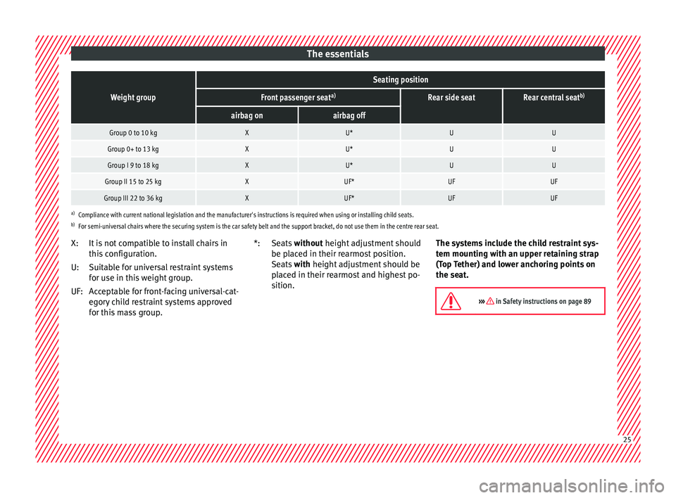
The seat belt may be used to secure univer-
sal type child seats to the vehicle seats
marked with a U in the table below.
● In the passenger seat without height ad-
justment
: It is necessary to place the passen-
ger seat in its rearmost position 1)
.
● In the passenger seat with height adjust-
ment: It
is necessary to place the passenger
seat in its rearmost and highest position 1)
.
To correctly use a child seat in the back, the
front backrest must be adjusted so that there
is no contact with the child seat in the back
in the case that it goes opposite to the direc-
tion of the car. In the case of front facing re-
straint systems, the front backrest must be
adjusted so that there is no contact with the
child's feet. To adjust the passenger seat to accommo-
date a c
hild's seat and get the seat belt in a
perfect position, adjust the passenger back-
rest as far forward as possible 1)
.
If a semi-universal type chair is to be instal-
led, in which the method of attachment to
the car is through the seat belt and support
bracket, it should never be installed in the
central rear seat as the ground clearance is
lower than in other places and the support
bracket will not allow the seat to remain suffi-
ciently stable. 1)
Compliance with current national legislation and
the manuf act
urer's instructions is required when us-
ing or installing child seats. 24
Page 27 of 308
The essentialsWeight group
Seating position
Front passenger seat
a)Rear side seatRear central seatb)
airbag onairbag off
Group 0 to 10 kgXU*UU
Group 0+ to 13 kgXU*UU
Group I 9 to 18 kgXU*UU
Group II 15 to 25 kgXUF*UFUF
Group III 22 to 36 kgXUF*UFUF
a)
Compliance with current national legislation and the manufacturer's instructions is required when using or installing child seats.
b) For semi-universal chairs where the securing system is the car safety belt and the support bracket, do not use them in the centre rear seat.
It is not compatible to install chairs in
this configuration.
Suitable for universal restraint systems
for use in this weight group.
Acceptable for front-facing universal-cat-
egory child restraint systems approved
for this mass group.
X:
U:
UF:
Seats
without height adjustment should
be pl aced in their rearmost position.
Seats with height adjustment should be
placed in their rearmost and highest po-
sition.
*:
The systems include the child restraint sys-
tem mountin
g with an upper retaining strap
(Top Tether) and lower anchoring points on
the seat.
››› in Safety instructions on page 89 25
Page 28 of 308
The essentials
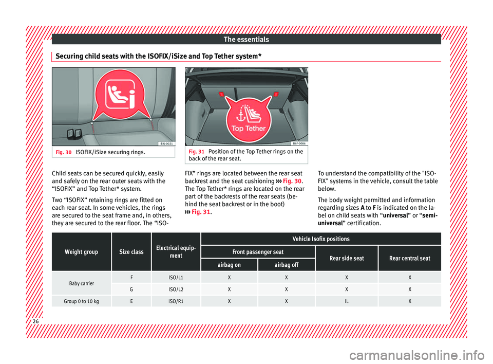
Securing child seats with the ISOFIX/iSize and Top Tether system* Fig. 30
ISOFIX/iSize securing rings. Fig. 31
Position of the Top Tether rings on the
bac k
of the rear seat. Child seats can be secured quickly, easily
and s
af
ely
on the rear outer seats with the
“ISOFIX” and Top Tether* system.
Two “ISOFIX” retaining rings are fitted on
each rear seat. In some vehicles, the rings are secured to the seat frame and, in others,
they are secured to the rear floor. The “ISO- FIX” rings are located between the rear seat
back
rest and the seat cushioning ››› Fig. 30.
The Top Tether* rings are located on the rear
part of the backrests of the rear seats (be-
hind the seat backrest or in the boot)
››› Fig. 31. To understand the compatibility of the "ISO-
FIX" syst
ems in the vehicle, consult the table
below.
The body weight permitted and information
regarding sizes A to F is indicated on the la-
bel on child seats with “ universal” or “semi-
universal” certification.
Weight groupSize classElectrical equip- ment
Vehicle Isofix positions
Front passenger seatRear side seatRear central seatairbag onairbag off
Baby carrierFISO/L1XXXX
GISO/L2XXXX
Group 0 to 10 kgEISO/R1XXILX26
Page 29 of 308
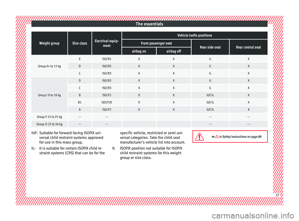
The essentialsWeight groupSize classElectrical equip-
ment
Vehicle Isofix positions
Front passenger seatRear side seatRear central seatairbag onairbag off
Group 0+ to 13 kg
EISO/R1XXILX
DISO/R2XXILX
CISO/R3XXILX
Group I 9 to 18 kg
DISO/R2XXILX
CISO/R3XXILX
BISO/F2XXIUF/ILX
B1ISO/F2XXXIUF/ILX
AISO/F3XXIUF/ILX
Group II 15 to 25 kg------ ------
Group III 22 to 36 kg------ ------ Suitable for forward-facing ISOFIX uni-
v
er s
al child restraint systems approved
for use in this mass group.
It is suitable for certain ISOFIX child re-
straint systems (CRS) that can be for the
IUF:
IL:
specific vehicle, restricted or semi-uni-
vers
al categories. Take the child seat
manufacturer's vehicle list into account.
ISOFIX position not suitable for ISOFIX
child restraint systems for this weight
group or size class.
X: ››› in Safety instructions on page 89
27
Page 30 of 308
The essentials
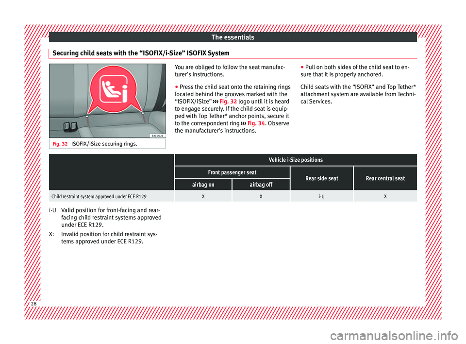
Securing child seats with the “ISOFIX/i-Size” ISOFIX System Fig. 32
ISOFIX/iSize securing rings. You are obliged to follow the seat manufac-
tur
er's
instructions.
● Press the child seat onto the retaining rings
located behind the gr
ooves marked with the
“ISOFIX/iSize” ››› Fig. 32 logo until it is heard
to engage securely. If the child seat is equip-
ped with Top Tether* anchor points, secure it
to the correspondent ring ››› Fig. 34. Observe
the manufacturer's instructions. ●
Pul
l on both sides of the child seat to en-
sure that it is properly anchored.
Child seats with the “ISOFIX” and Top Tether*
attachment system are available from Techni-
cal Services.
Vehicle i-Size positions
Front passenger seatRear side seatRear central seatairbag onairbag off
Child restraint system approved under ECE R129XXi-UX Valid position for front-facing and rear-
f
ac
in
g child restraint systems approved
under ECE R129.
Invalid position for child restraint sys-
tems approved under ECE R129.
i-U
X:
28