technical data Seat Arona 2017 Owner's Guide
[x] Cancel search | Manufacturer: SEAT, Model Year: 2017, Model line: Arona, Model: Seat Arona 2017Pages: 308, PDF Size: 6.66 MB
Page 109 of 308

Fuses and bulbs
Side turn signals Fig. 119
Turn signal integrated in the rear
v iew mirr
or The side turn signals are LEDS and are inte-
gr
at
ed in the r
ear view mirrors.
In case of failure, go to an authorised work-
shop to have it replaced.
Additional brake light Given the difficulty involved in the replace-
ment
of
thi
s light it should be done by Tech-
nical Services. Changing the interior bulbs
Interior light and fr
ont reading lights Fig. 120
Front reading light. To remove the glass
– Insert a fine screwdriver between the cas-
ing and the gl
a
ss ››› Fig. 120.
– Carefully remove the glass, levering it to
avoid pos
sible damage.
To replace the bulbs
– Pull the bulbs outwards.
– To remove the central bulb, hold and press
to one side.
As
sembly
– Proceed in the reverse order, pressing gen-
tly on the outer edg
e of the side light. –
First
fit the glass with the fastening tabs
over the frame of the switch. Next press the
front part until the two long tabs click on
the support. Note
In LED courtesy lights it is not possible to re-
pl ac
e the light sources. If the light does not
work, take the vehicle to an official Service. 107
Technical data
Advice
Operation
Emergencies
Safety
Page 113 of 308
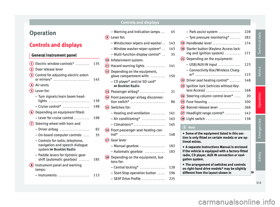
Controls and displays
Operation
C ontr
o
ls and displays
General instrument panel Electric window controls*
. . . . . . . . .135
Door release lever
Contr o
l for adjusting electric exteri-
or mirrors* . . . . . . . . . . . . . . . . . . . . . . . 145
Air vents
Lev er f
or:
– Turn signals/main beam head-
lights . . . . . . . . . . . . . . . . . . . . . . . . . . 139
– Crui se c
ontrol* . . . . . . . . . . . . . . . . . 198
Depending on equipment fitted:
– Lev er f
or cruise control . . . . . . . . . .198
Steering wheel with horn and – Driver airbag . . . . . . . . . . . . . . . . . . . 82
– On-boar d c
omputer controls . . . .35
– Contro
ls for radio, telephone,
navigation and speech dialogue
system ›››
Booklet Radio
– Paddle levers for tiptronic gear-
shift (automatic gearbox) . . . . . . .185
Instrument panel and warning
lamp s:
– In
struments . . . . . . . . . . . . . . . . . . . . 113
1 2
3
4
5
6
7
8 –
Warnin
g and indic
ation lamps . . .45
Lever for:
– Winds
creen wipers and washer . .143
– Window w
asher-wiper system* . .143
– Multi-f
unction display control* . .35
Infotainment system:
Hazard w
arning lights . . . . . . . . . . . . 141
Depending on the equipment,
glove c
ompartment with: . . . . . . . . .150
– CD pla
yer* and/or SD card*
››› Booklet Radio
Passenger airbag* . . . . . . . . . . . . . . . . 21
Front passenger airbag disconnec-
tion switc
h* . . . . . . . . . . . . . . . . . . . . . . 86
Switches for:
– Heating and
ventilation . . . . . . . . . 161
– Air conditionin g* . . . . . . . . . . . . . . . 163
– C
limatr
onic* . . . . . . . . . . . . . . . . . . . . 165
Front passenger seat heating con-
tro l* . . . . . . . . . . . . . . . . . . . . . . . . . . . . . 148
Ge
ar lever
– Manual g
earbox . . . . . . . . . . . . . . . . 183
– Autom atic
gearbox . . . . . . . . . . . . . 183
Depending on the equipment, but-
ton s
for:
– Central locking* . . . . . . . . . . . . . . . . 128
– Star t
-Stop operation button . . . . .196
– SEAT Driv
e Profile . . . . . . . . . . . . . . . 225
9
10
11
12
13
14
15
16
17
18 –
Park
a
ssist system . . . . . . . . . . . . . . 228
– Tyr
e pressure monitoring* . . . . . . .282
Handbrake lever . . . . . . . . . . . . . . . . . . 174
Starter button (Keyless Access lock-
ing and ignition sys
tem) . . . . . . . . . . 171
Depending on the equipment:
– USB/AUX-IN inp
ut . . . . . . . . . . . . . . 123
– Connectivity
Box/Wireless Charg-
er* . . . . . . . . . . . . . . . . . . . . . . . . . . . . . 123
Driver seat heating control* . . . . . . .148
Ignition lock (vehicles without Key-
les
s Access) . . . . . . . . . . . . . . . . . . . . . . 168
Steering column control lever* . . . .20
Fuse housing . . . . . . . . . . . . . . . . . . . . . 100
Bonnet release lever . . . . . . . . . . . . . .268
Headlight range control* . . . . . . . . . .142
Light switch . . . . . . . . . . . . . . . . . . . . . . 138 Note
● Some of the equipment li
sted in this sec-
tion is only fitted on certain models or are op-
tional extras.
● A separate Instructions Manual is enclosed
if the v
ehicle is equipped with a factory-fitted
radio, CD player, AUX IN connection or navi-
gation system.
● The arrangement of switches and controls
on right-hand driv
e models* may be slightly
different from the layout shown in » 19
20
21
22
23
24
25
26
27
28
111
Technical data
Advice
Operation
Emergencies
Safety
Page 115 of 308
Instruments and warning/control lamps
Instruments and warning/control lamps
In s
trument
s
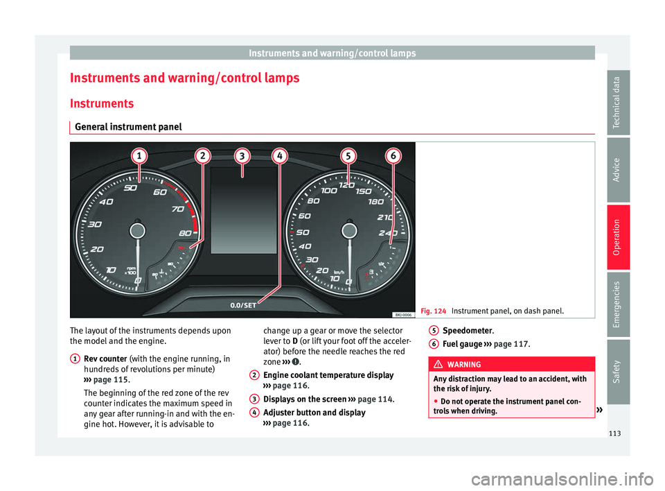
General instrument panel Fig. 124
Instrument panel, on dash panel. The layout of the instruments depends upon
the model
and the en
gine.
R
ev counter (with the engine running, in
hundreds of revolutions per minute)
››› page 115.
The beginning of the red zone of the rev
counter indicates the maximum speed in
any gear after running-in and with the en-
gine hot. However, it is advisable to
1 change up a gear or move the selector
l
ev
er t
o D (or lift your foot off the acceler-
ator) before the needle reaches the red
zone ››› .
En gine c
oo
lant temperature display
››› page 116.
Displays on the screen ››› page 114.
Adjuster button and display
››› page 116.
2 3
4 Speedometer.
F
uel
g
auge ››› page 117. WARNING
Any distraction may lead to an accident, with
the risk of
injury.
● Do not operate the instrument panel con-
trol
s when driving. » 5
6
113
Technical data
Advice
Operation
Emergencies
Safety
Page 117 of 308
Instruments and warning/control lamps
Speed warning
When the s peed settin
g i
s exceeded, this will
be indicated on the instrument panel display.
This is very useful, for example when using
winter tyres that are not designed for driving
at the maximum speed of the vehicle
››› page 40.
The speed warning settings can be adjusted
in the Easy Connect system via the button
and the S
ET
TINGS function button
› ›
›
page 118.
Start-Stop operating display
Updated information relating to the status is
displayed on the instrument panel
››› page 196.
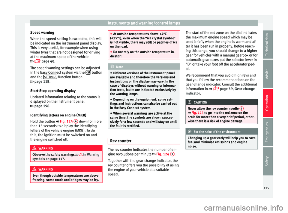
Identifying letters on engine (MKB)
Hold the button ››› Fig. 124 4 down for more
th an 15 sec
ond
s to display the identifying
letters of the vehicle engine (MKB). To do
this, the ignition must be switched on and
the engine switched off. WARNING
Observe the safety warnings ›››
in Warning
symbol s on p
age 117. WARNING
Even though outside temperatures are above
freez in
g, some roads and bridges may be icy. ●
At out s
ide temperatures above +4°C
(+39°F), even when the “ice crystal symbol”
is not visible, there may still be patches of ice
on the road.
● Do not rely on the outside temperature in-
dicator! Note
● Diff erent
versions of the instrument panel
are available and therefore the versions and
instructions on the display may vary. In the
case of displays without warning or informa-
tion texts, faults are indicated exclusively by
the warning lamps.
● Depending on the equipment, some set-
tings
and instructions can also be carried out
in the Easy Connect system.
● When several warnings are active at the
same time, the symbol
s are shown succes-
sively for a few seconds and will stay on until
the fault is rectified. Rev counter
The rev counter indicates the number of en-
gine r
ev
o
lutions per minute ››› Fig. 124 1 .
T og
ether w
ith the gear-change indicator, the
rev counter offers you the possibility of using
the engine of your vehicle at a suitable
speed. The start of the red zone on the dial indicates
the maximum en
gine speed which may be
used briefly when the engine is warm and af-
ter it has been run in properly. Before reach-
ing this range, you should change to a higher
gear for vehicles with a manual gearbox or for
automatic gearboxes put the selector lever in
“D” or take your foot off the accelerator ped-
al.
We recommend that you avoid high revs and
that you follow the recommendations on the
gear-change indicator. Consult the additional
information in ›››
page 39, Gear-change
indicator. CAUTION
Never allow the rev counter needle 1 ›››
Fig. 124 to g o int
o the red zone on the
scale for more than a very brief period, other-
wise there is a risk of engine damage. For the sake of the environment
Changing up a gear early will help you to save
fuel and minimi
se emissions and engine
noise. 115
Technical data
Advice
Operation
Emergencies
Safety
Page 119 of 308
Instruments and warning/control lamps
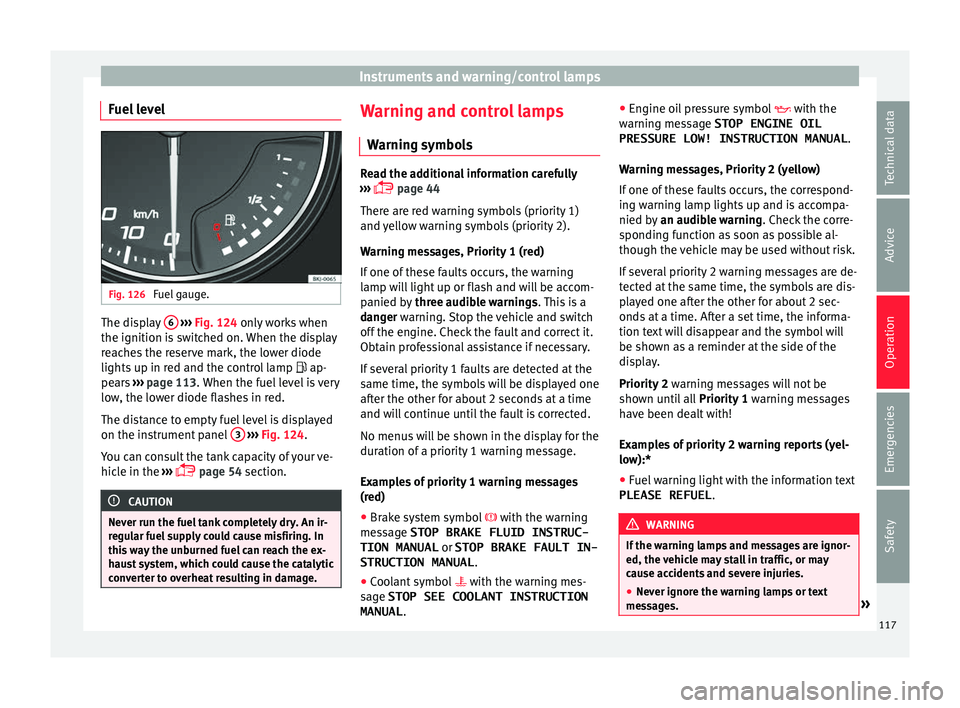
Fuel level Fig. 126
Fuel gauge. The display
6
› ›
› Fig. 124 only works when
the ignition is switched on. When the display
reaches the reserve mark, the lower diode
lights up in red and the control lamp ap-
pears ››› page 113. When the fuel level is very
low, the lower diode flashes in red.
The distance to empty fuel level is displayed
on the instrument panel 3
› ›
› Fig. 124
.
You can consult the tank capacity of your ve-
hicle in the ›››
page 54 section. CAUTION
Never run the fuel tank completely dry. An ir-
re gu
lar fuel supply could cause misfiring. In
this way the unburned fuel can reach the ex-
haust system, which could cause the catalytic
converter to overheat resulting in damage. Warning and control lamps
W arnin
g symbo
ls Read the additional information carefully
›› ›
page 44
There are red warning symbols (priority 1)
and yellow warning symbols (priority 2).
Warning messages, Priority 1 (red)
If one of these faults occurs, the warning
lamp will light up or flash and will be accom-
panied by three audible warnings. This is a
danger warning. Stop the vehicle and switch
off the engine. Check the fault and correct it.
Obtain professional assistance if necessary.
If several priority 1 faults are detected at the
same time, the symbols will be displayed one
after the other for about 2 seconds at a time
and will continue until the fault is corrected.
No menus will be shown in the display for the
duration of a priority 1 warning message.
Examples of priority 1 warning messages
(red)
● Brake system symbol with the warnin
g
message STOP BRAKE FLUID INSTRUC-
TION MANUAL or STOP BRAKE FAULT IN-
STRUCTION MANUAL .
● Coolant symbol with the warnin
g mes-
sage STOP SEE COOLANT INSTRUCTION
MANUAL . ●
Engine oil
pressure symbol with the
warning message STOP ENGINE OIL PRESSURE LOW! INSTRUCTION MANUAL .
Warning messages, Priority 2 (yellow)
If one of these faults occurs, the correspond-
ing warning lamp lights up and is accompa-
nied by an audible warning. Check the corre-
sponding function as soon as possible al-
though the vehicle may be used without risk.
If several priority 2 warning messages are de-
tected at the same time, the symbols are dis-
played one after the other for about 2 sec-
onds at a time. After a set time, the informa-
tion text will disappear and the symbol will
be shown as a reminder at the side of the
display.
Priority 2 warning messages will not be
shown until all Priority 1 warning messages
have been dealt with!
Examples of priority 2 warning reports (yel-
low):*
● Fuel warning light with the information text
PLEASE REFUEL . WARNING
If the warning lamps and messages are ignor-
ed, the v ehic
le may stall in traffic, or may
cause accidents and severe injuries.
● Never ignore the warning lamps or text
mess
ages. » 117
Technical data
Advice
Operation
Emergencies
Safety
Page 121 of 308
Communications and multimedia
Communications and multi-
medi a
St eerin
g wheel controls*
General information The steering wheel includes a multifunction
modul
e fr
om where it is possible to control
the audio, telephone and radio/navigation
functions without needing to distract the
driver.
There are two versions of the multifunction
module:
● Audio system + telephone without voice
contr o
l version (MID) : for controlling the au-
dio functions available (radio, audio CD,
MP3, iPod ®1)
, USB 1)
, SD 1)
) and Bluetooth sys-
tem from the steering wheel.
● Audio system + telephone with voice con-
trol
version (HIGH) : for controlling the audio
functions available (radio, audio CD, MP3,
iPod ®1)
, USB 1)
, SD 1)
) and Bluetooth system
from the steering wheel. 1)
Depending on the vehicle equipment.
119
Technical data
Advice
Operation
Emergencies
Safety
Page 123 of 308
Communications and multimediaButtonRadioMedia (except AUX)AUXTelephoneNavigation*
HTurn: Next/previous preset
b)
Press: Acts on the MFDTurn: Next/previous song b)
Press: Acts on the MFDTurn: No function
Press: Acts on the MFD
Turn: Access to call list / selec- tion of action on incoming call or active call (answer/hang-
up/ignore/hold/mute/switch to private mode).
Press: Confirm the selected ac- tion by turning.
Turn: Changes menu or memo-ry on instrument panel
Press: Operates on instrument panel
a)According to the vehicle's equipment package.
b) Only if the dash panel is in audio menu.
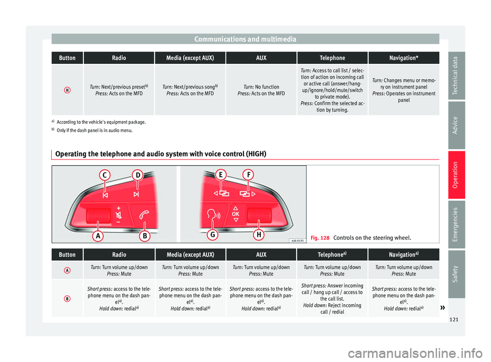
Operating the telephone and audio system with voice control (HIGH) Fig. 128
Controls on the steering wheel.
ButtonRadioMedia (except AUX)AUXTelephone a)Navigation a)
ATurn: Turn volume up/down
Press: MuteTurn: Turn volume up/downPress: MuteTurn: Turn volume up/downPress: MuteTurn: Turn volume up/downPress: MuteTurn: Turn volume up/downPress: Mute
B
Short press: access to the tele-
phone menu on the dash pan- ela)
.
Hold down: redial a)Short press:
access to the tele-
phone menu on the dash pan- ela)
.
Hold down: redial a)Short press:
access to the tele-
phone menu on the dash pan- ela)
.
Hold down: redial a)Short press:
Answer incoming
call / hang up call / access to the call list.
Hold down: Reject incoming call / redialShort press: access to the tele-
phone menu on the dash pan- ela)
.
Hold down: redial a)
» 121
Technical data
Advice
Operation
Emergencies
Safety
Page 125 of 308
Communications and multimedia
Multimedia USB/A UX
-INP
ortFig. 129
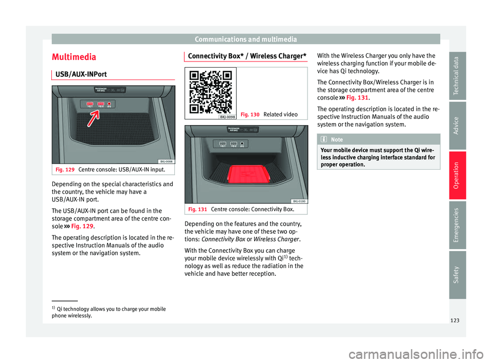
Centre console: USB/AUX-IN input. Depending on the special characteristics and
the c
ou
ntr
y, the vehicle may have a
USB/AUX-IN port.
The USB/AUX-IN port can be found in the
storage compartment area of the centre con-
sole ››› Fig. 129.
The operating description is located in the re-
spective Instruction Manuals of the audio
system or the navigation system. Connectivity Box* / Wireless Charger* Fig. 130
Related video Fig. 131
Centre console: Connectivity Box. Depending on the features and the country,
the
v
ehic
le may have one of these two op-
tions: Connectivity Box or Wireless Charger.
With the Connectivity Box you can charge
your mobile device wirelessly with Qi 1)
tech-
nology as well as reduce the radiation in the
vehicle and have better reception. With the Wireless Charger you only have the
wirel
ess charging function if your mobile de-
vice has Qi technology.
The Connectivity Box/Wireless Charger is in
the storage compartment area of the centre
console ››› Fig. 131.
The operating description is located in the re-
spective Instruction Manuals of the audio
system or the navigation system. Note
Your mobile device must support the Qi wire-
le s
s inductive charging interface standard for
proper operation. 1)
Qi technology allows you to charge your mobile
phone wir el
essly. 123
Technical data
Advice
Operation
Emergencies
Safety
Page 127 of 308
Opening and closing
Locking the vehicle ››
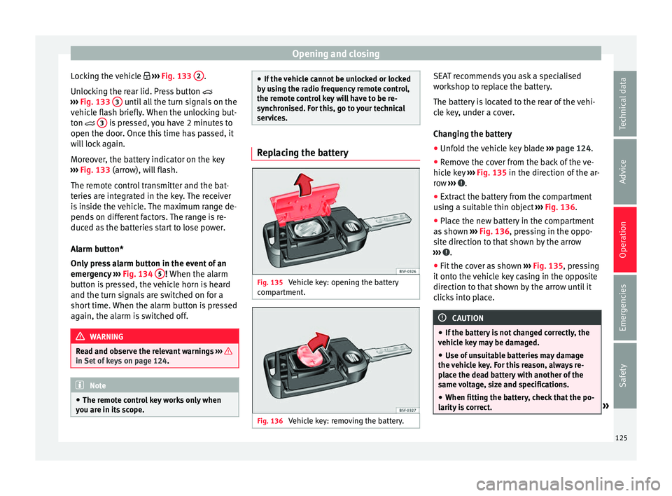
› Fig. 133 2 .
Un loc
k
ing the rear lid. Press button
››› Fig. 133 3 until all the turn signals on the
v ehic
l
e flash briefly. When the unlocking but-
ton 3 is pressed, you have 2 minutes to
open the door . Onc
e thi
s time has passed, it
will lock again.
Moreover, the battery indicator on the key
››› Fig. 133 (arrow), will flash.
The remote control transmitter and the bat-
teries are integrated in the key. The receiver
is inside the vehicle. The maximum range de-
pends on different factors. The range is re-
duced as the batteries start to lose power.
Alarm button*
Only press alarm button in the event of an
emergency ››› Fig. 134 5 ! When the al
arm
b utt
on is pressed, the vehicle horn is heard
and the turn signals are switched on for a
short time. When the alarm button is pressed
again, the alarm is switched off. WARNING
Read and observe the relevant warnings ›››
in Set of keys on page 124.
Note
● The remot e c
ontrol key works only when
you are in its scope. ●
If the v
ehicle cannot be unlocked or locked
by using the radio frequency remote control,
the remote control key will have to be re-
synchronised. For this, go to your technical
services. Replacing the battery
Fig. 135
Vehicle key: opening the battery
c omp
ar
tment. Fig. 136
Vehicle key: removing the battery. SEAT recommends you ask a specialised
w
ork
shop t
o replace the battery.
The battery is located to the rear of the vehi-
cle key, under a cover.
Changing the battery ● Unfold the vehicle key blade ›››
page 124.
● Remove the cover from the back of the ve-
hicle k
ey ››› Fig. 135 in the direction of the ar-
row ››› .
● Extract the battery from the compartment
u s
in
g a suitable thin object ››› Fig. 136.
● Place the new battery in the compartment
as sho
wn ››› Fig. 136, pressing in the oppo-
site direction to that shown by the arrow
››› .
● Fit the cover as shown ››
›
Fig. 135 , pressing
it onto the vehicle key casing in the opposite
direction to that shown by the arrow until it
clicks into place. CAUTION
● If the b att
ery is not changed correctly, the
vehicle key may be damaged.
● Use of unsuitable batteries may damage
the vehic
le key. For this reason, always re-
place the dead battery with another of the
same voltage, size and specifications.
● When fitting the battery, check that the po-
larity i
s correct. » 125
Technical data
Advice
Operation
Emergencies
Safety
Page 129 of 308
Opening and closing
Note
For anti-theft security, only the driver door is
fitted w ith a loc
k cylinder.“Safe” security system*
This is an anti-theft device which consists of
a doubl
e loc
k for the door locks and a deacti-
vation function for the boot in order to pre-
vent forced entry.
Activation
The “safe” system is activated when the vehi-
cle is locked using the key or the remote con-
trol.
To activate it with the key, rotate once it is in-
serted in the door lock cylinder in the locking
direction.
To activate the system using the remote con-
trol, press the lock button once on the re-
mote.
Once this system is activated, opening doors
from the outside and the inside is not possi-
ble. The rear lid can not be opened. The cen-
tral lock button does not work.
When the ignition is switched off, the instru-
ment panel display indicates that the “Safe”
system is on. Deactivation
Rot
at
e the key inserted in the lock cylinder
twice towards the locking direction.
To activate the system using the remote con-
trol, press the lock button on the remote
twice in less than five seconds.
On deactivating the “Safe” system, the alarm
volumetric sensor is also deactivated.
With the “Safe” switched off, doors can be
opened from the interior but not from the ex-
terior.
See “Selective unlocking system*”
“Safe” status
On the driver door, there is warning lamp visi-
ble from outside the vehicle through the win-
dow which shows the “Safe” system status.
We will know that “Safe” system is activated
by the flashing warning lamp. The indicator
will flash on all vehicles, fitted and nor fitted
with an alarm, until they unlock.
Remember:
Safe activated with or without an alarm:
warning lamp flashes continuously.
Safe deactivated without an alarm: the warn-
ing lamp stays off.
Safe deactivated with an alarm: the warning
lamp stays off. WARNING
No one should remain inside the vehicle if the
“Safe” sy s
tem is activated because opening
the doors will not be possible in the event of
an emergency neither from the inside nor the
outside and help from the outside is made
difficult. Danger of death. Passengers could
become trapped inside in case of emergency. Selective unlocking system*
This system allows to unlock either just the
driv
er door or al
l
the vehicle.
Driver door unlock button
Unlock once. Use either the key or the remote
control.
Once the key is inserted in the lock cylinder,
rotate once in the unlock direction. The driver
door will remain without “Safe” and un-
locked. In vehicles fitted with an alarm, see
the Anti-theft Alarm section ›››
page 132.
Using the remote control, press the unlock
button on the remote once. The “Safe” sys-
tem for all the vehicle is deactivated, only the
driver door is unlocked and both the alarm
and the warning lamp are also turned off. »
127
Technical data
Advice
Operation
Emergencies
Safety