driver seat adjustment Seat Arona 2018 Owner's Manual
[x] Cancel search | Manufacturer: SEAT, Model Year: 2018, Model line: Arona, Model: Seat Arona 2018Pages: 316, PDF Size: 6.77 MB
Page 20 of 316

The essentials
● To lif
t
the bonnet, press towards the left on
the lever located under the bonnet, in the
centre ››› Fig. 10 2 . The arrester hooks are
r el
e
ased.
● Release the bonnet stay and secure it in
the fixtur
e designed for this in the bonnet.
››› in Safety notes for work in the en-
gine compartment on page 273
››› page 273 Controls for the windows
Fig. 11
Detail of the driver door: controls for
the w indo
w
s. ●
Opening the window: Press the butt
on.
● C
losing the window: Pull the button.B
uttons on the driver door
Window on the fr
ont left door
Window on the front right door
Window on the rear left door
Window on the rear right door
Safety switch for deactivating the electric
window buttons in the rear doors.
››› in Opening and closing of the elec-
tric windows on page 141
››› page 141 Before driving
R el
at
ed video Fig. 12
Vehicle interior 1
2
3
4
5 Manually adjusting the front seats
Fig. 13
Front seats: manual seat adjustment. Forward/back: pull the lever and move
the se
at
f
orwards or backwards.
Raising/lowering: pull/push the lever.
Tilting the backrest: turn the hand wheel.
››› in Adjusting the front seats on
page 152 1
2
3
18
Page 45 of 316

The essentials
● Vehicle
s
with Easy Connect : Press the button and the function button SETTINGS >
Driver assistance > ACC > Dis-
tance .
The w arnin
g limit
can be set from 30 to
210 km/h (18 to 150 mph) ›››
page 207.
The adjustment is made at 10 km/h (6 mph)
intervals. Note
● Ple a
se bear in mind that, even with the
speed warning function, it is still important
to keep an eye on the vehicle speed with the
speedometer and to observe the legal speed
limits.
● The speed limit warning function in the ver-
sion for some c
ountries warns you at a speed
of 120 km/h (75 mph). This is a factory-set
speed limit. Service intervals
Fig. 50
Instrument panel The service interval indication appears on the
in
s
trument
panel display ››› Fig. 50 1 .
S EA
T di
stinguishes between services with en-
gine oil change (e.g. Oil change service) and
services without engine oil change (e.g. In-
spection).
In vehicles with Services established by time
or mileage, the service intervals are already
pre-defined.
In vehicles with LongLife Service , the inter-
vals are determined individually. Thanks to
technological progress, maintenance work
has been greatly reduced. Because of the
technology used by SEAT, with this service
you only need to change the oil when the ve- hicle so requires. To calculate this change
(max. 2 y
ears), the vehicle's conditions of
use and individual driving styles are consid-
ered. The advance warning first appears 20
days before the date established for the cor-
responding service. The kilometres (miles)
remaining until the next service are always
rounded up to the nearest 100 km (miles)
and the time is given in complete days. The
current service message cannot be viewed
until 500 km after the last service. Prior to
this, only lines are visible on the display.
Inspection reminder
When the Service date is approaching, when
the ignition is switched on a Service remind-
er is displayed.
Vehicles without text messages : a span-
ner will be displayed on the instrument
panel plus an indication in km.
The kilometres indicated are the maximum
number of kilometres that can be travelled
until the next service. After a few seconds,
the display mode changes. A clock symbol
appears and the number of days until the
next service is due.
Vehicles with text messages : Service in
--- km or --- days will be shown on the
instrument panel display. » 43
Page 54 of 316

The essentials1TemperatureThe left and right sides can be adjusted separately: turn the control to adjust the temperature.
2FanThe power of the fan is automatically adjusted. Press the buttons to manually adjust the fan.
3Air distributionThe airflow adjusts automatically for comfort. You can also switch it on manually using the buttons
3.
4Indications on the display screen of the fan speed and the temperature selected for the right and left sides.
Defrost functionThe air drawn in from outside the vehicle is directed at the windscreen and air recirculation is automatically switched off. To defrost the wind-
screen more quickly, the air is dehumidified at temperatures over approximately +3°C (+38°F) and the fan runs at maximum output.
The air is directed at the chest of driver and passengers by the dash panel air vents.
Air distribution towards the footwell.
Upward air distribution.
Heated rear window: this only works when the engine is running and switches off automatically after a maximum of 10 minutes.
Air recirculation
Seat heating buttons
Press the button to switch on or off the cooling system.
Press the button to apply the driver-side settings to the passenger side. Use the temperature regulator for the passenger side in order to set
a different temperature.
Automatic adjustment of temperature, fan, and air distribution.
Switching offPress the button or manually set the fan to .
52
Page 78 of 316

:
● three-point seat belts,
● Belt tension limiter for the front and rear
side seats
● belt
te")
Safety
risk of injury. The following points cover part
of the s
af
ety equipment in your SEAT 1)
:
● three-point seat belts,
● Belt tension limiter for the front and rear
side seats
● belt
tensioners for the front and rear seats,
● front airbags,
● side airbags in the front seat backrests,
● “ISOFIX” anchor points for “ISOFIX” rear
chil
d seat system
● height-adjustable front head restraints,
● Rear-centre head restraints with in-use po-
sition and non-use po
sition
● adjustable steering column.
The safety
equipment mentioned above
works together to provide you and your pas-
sengers with the best possible protection in
the event of an accident. However, these
safety systems can only be effective if you
and your passengers are sitting in a correct
position and use this equipment properly.
Safety is everyone's business! Correct position of the vehicle
occup
ants
Correct sitting position for the driver Fig. 92
The proper distance between driver
and s t
eerin
g wheel. Fig. 93
Correct head restraint position for the
driv er
. For your own safety and to reduce the risk of
injur
y
in the ev
ent of an accident, we recom-
mend the following adjustments for the driv-
er:
– Adjust the steering wheel so that there is a
dist
ance of at least 25 cm between the
steering wheel and the centre of your chest
››› Fig. 92.
– Move the driver's seat forwards or back-
ward
s so that you are able to press the ac-
celerator, brake and clutch pedals to the
floor with your knees still slightly angled
››› .
– Ensure that you can reach the highest point
of the s
t
eering wheel.
– Adjust the head restraint so that its upper
edge is
at the same level as the top of your
head, or as close as possible to the same
level as the top of your head ››› Fig. 93.
– Move the seat backrest to an upright posi-
tion so that
your back rests completely
against it.
– Fasten your seat belt securely ›››
page 81.
– Keep both feet in the footwell so that you
have the
vehicle under control at all times.
Adjustment of the driver's seat ››› page 152. 1)
Depending on the version/market.
76
Page 79 of 316

Safe driving
WARNING
● An incorr ect
sitting position of the driver
can lead to severe injuries.
● Adjust the driver's seat so that there is at
lea
st 25 cm distance between the centre of
the chest and the centre of the steering
wheel ››› Fig. 92. If distance is less than 25
cm, the airbag system may not protect you
properly.
● If your physical constitution prevents you
from maint
aining the minimum distance of 25
cm, contact a specialised workshop. The
workshop will help you decide if special spe-
cific modifications are necessary.
● When driving, always hold the steering
wheel with both h
ands on the outside of the
ring at the 9 o'clock and 3 o'clock positions.
This reduces the risk of injury when the driver
airbag is triggered.
● Never hold the steering wheel at the 12
o'clock
position, or in any other manner (e.g.
in the centre of the steering wheel). In such
cases, if the airbag is triggered, you may sus-
tain injuries to the arms, hands and head.
● To reduce the risk of injury to the driver
during sud
den braking manoeuvres or an ac-
cident, never drive with the backrest tilted far
back! The airbag system and seat belts can
only provide optimal protection when the
backrest is in an upright position and the
driver is wearing his or her seat belt correct-
ly.
● Adjust the head restraint properly to ach-
ieve optima
l protection. Adjusting the steering wheel position
Read the additional information carefully
›› ›
page 20 WARNING
● Never a dju
st the position of the steering
wheel when the vehicle is moving, as this
could cause an accident.
● Move the lever up firmly so the steering
wheel pos
ition does not accidentally change
during driving. risk of accident!
● Make sure you are capable of reaching and
firmly ho
lding the upper part of the steering
wheel: risk of accident!
● If you adjust the steering wheel so that it
points t
owards your face, the driver airbag
will not protect you properly in the event of
an accident. Make sure that the steering
wheel points towards your chest. Correct position for the front passen-
g
er For your own safety and to reduce the risk of
injur
y
in the ev
ent of an accident, we recom-
mend the following adjustments for the front
passenger:
– Move the front passenger seat back as far
as po
ssible ››› .–
Mo v
e the se
at backrest to an upright posi-
tion so that your back rests completely
against it.
– Adjust the head restraint so that its upper
edge is
at the same level as the top of your
head, or as close as possible to the same
level as the top of your head ››› page 79.
– Always keep both feet in the footwell in
front of
the front passenger seat.
– Fasten your seat belt securely ›››
page 81.
It is possible to deactivate the front passen-
ger airbag in exceptional circumstances
››› page 90.
Adjusting the front passenger seat
››› page 18. WARNING
● An incorr ect
sitting position of the front
passenger can lead to severe injuries.
● Adjust the front passenger seat so that
there is
at least 25 cm between your chest
and the dash panel. If distance is less than
25 cm, the airbag system may not protect you
properly.
● If your physical constitution prevents you
from maint
aining the minimum distance of 25
cm, contact a specialised workshop. The
workshop will help you decide if special spe-
cific modifications are necessary. » 77
Technical data
Advice
Operation
Emergencies
Safety
Page 82 of 316

››› Fig. 95. In this position, the head re-
stra")
Safety
Rear head restraints – The rear head restraints have 2 positions:
use
and
non-use.
– One position for use (he
ad restraint raised)
››› Fig. 95. In this position, the head re-
straints are used normally, protecting pas-
sengers along with the rear seat belts.
– And one position for non-use (he
ad re-
straint lowered).
– To fit the head restraints in position for use,
pul
l on the edges with both hands in the
direction of the arrow. WARNING
● Under no cir c
umstances should the rear
passengers travel while the head restraints
are in the non-use position. See the warning
label located on the rear side fixed window
››› Fig. 96.
● Do not swap the centre rear head restraint
with either of the out
er seat rear head re-
straints. Risk of injury in case of an accident! CAUTION
Note the instructions on the adjustment of
the hea d r
estraints ››› page 152. Pedal area
P ed
a
ls –
Ensure that you can always press the accel-
erat or
, brake and clutch pedals unimpaired
to the floor.
– Ensure that the pedals can return unim-
paired t
o their initial positions.
– Ensure that the floor mats are securely fas-
tened during the trip and do not
obstruct
the pedals ››› .
On ly
u
se floor mats which leave the pedals
clear and which are secured to prevent them
from slipping. You can obtain suitable floor
mats from a specialised dealership.
If a brake circuit fails, the brake pedal must
be pressed down thoroughly in order to stop
the vehicle.
Wear suitable footwear
Always wear shoes which support your feet
properly and give you a good feeling for the
pedals. WARNING
● If the ped a
ls are obstructed, an accident
may occur. Risk of serious injuries.
● Never lay or fit floor mats or other floor cov-
erings
over the original floor mats. This would reduce the pedal area and could ob-
struct
the ped
als. Risk of accident.
● Never place objects in the driver footwell.
An obj
ect could move into the pedal area and
impair pedal operation. In the event of a sud-
den driving or braking manoeuvre, you will
not be able to operate the brake, clutch or ac-
celerator pedal. Risk of accident! 80
Page 154 of 316

Operation
Note
● If the el ectric
al adjustment ever fails to op-
erate, the mirrors can be adjusted by hand by
lightly pressing the edge of the mirror glass.
● In vehicles with electric exterior mirrors,
the fol
lowing points should be observed: if,
due to an external force (e.g. being knocked
while manoeuvring), the adjustment of the
mirror housing is altered, the mirror will have
to be fully folded electrically. Do not readjust
the rear vision mirror housing by hand, as
this will interfere with the mirror adjuster
function.
● The fold-in function on the exterior mirrors
wil
l not activate at speeds over 40 km/h
(25 mph). Seats and head restraints
Adju
s
tin
g the seat and head re-
straints
Adjusting the front seats Read the additional information carefully
›› ›
page 18 WARNING
The safe driving chapter contains important
inform ation, tip
s, suggestions and warnings
that you should read and observe for your
own safety and the safety of your passengers
››› page 75. WARNING
● Never a dju
st the driver or front passenger
seat while the vehicle is in motion. While ad-
justing your seat, you will assume an incor-
rect sitting position. Risk of accidents. Adjust
the driver or front passenger seat only when
the vehicle is stationary.
● To reduce the risk of injury to the driver and
front p
assenger in case of a sudden braking
or an accident, never drive with the backrest
tilted towards the rear. The maximum protec-
tion of the seat belt can be achieved only
when the backrests are in an upright position
and the driver and front passenger have prop-
erly adjusted their seat belts. The further the backrests are tilted to the rear, the greater
the risk
of
injury due to improper positioning
of the belt web!
● Exercise caution when securing the seat
height into f
orwards/backwards position. In-
juries can be caused if the seat height is ad-
justed without due care and attention.
● To move the seat forwards and backwards,
pul
l upwards and not sideways on the lever,
as the force exerted on it in that direction
could damage it. Adjusting the front head restraints
Read the additional information carefully
› ›
›
page 19
Adjust the head restraint ›››
page 19 so
that as far as possible the top of the head re-
straint is level with the top of your head.
When this is not possible, try to get as close
as possible to this position. WARNING
● Never driv e if
the head restraints have been
removed. Risk of injury.
● After refitting the head restraint, you must
alwa
ys adjust it properly for height to achieve
optimal protection.
● Please observe the safety warnings ›››
in
Corr ect
adjustment of front head restraints on
page 79. 152
Page 155 of 316

Seats and head restraints
Note
● When fitting the he a
d restraints again, in-
sert the tubes as far as possible into the
guides without pressing the button. Adjustment of the rear head restraints
Fig. 153
Rear centre head restraint: release
point . When transporting people in the back seat,
p
l
ac
e the head restraints of the occupied
seats at a minimum of the next socket up
››› .
Adju s
tin
g the head restraints
– To set the head restraint higher, grasp the
sides
with both hands and move it up-
wards, until you see it engage. –
To set the he
ad restraint lower down, press
the 1
› ››
Fig. 153
b utton and move it
downwards.
Removing the head restraint
To remove the head restraint, the correspond-
ing backrest must be partially folded forward. – Unlock the backrest ›››
page 155.
– Move the head restraint upwards until it ar-
rives
to the top.
– Press button 1 , while simultaneously
pr e
s
sing on the security hole 2 with a flat
s c
r
ewdriver a maximum of 5 mm wide, and
remove the head restraint.
– Move the backrest until it engages properly
›››
.
Fittin g the he
a
d restraint
To mount the external head restraints, the
corresponding backrest must be partially fol-
ded forward.
– Unlock the backrest ›››
page 155.
– Insert the head restraint bars into the
guides u
ntil they perceptibly engage. It
should not be possible to remove the head
restraint from the backrest.
– Move the backrest until it engages properly
›››
. WARNING
● Ple a
se observe the general notes
››› page 79.
● Remove the rear head restraints only when
it is
necessary for the placement of a child
seat ››› page 92. After removing a child seat,
remount the head restraint immediately.
Travelling with the head restraints removed
or improperly adjusted increases the risk of
severe injuries. Seat functions
Intr oduction WARNING
Inappropriate use of the seat functions can
cau se sev
ere injuries.
● Assume the proper sitting position before
your trip and rem
ain in it throughout. This al-
so applies to the other occupants.
● Always keep hands, fingers, feet and other
part
s of the body away from the operating ra-
dius and the adjustment of seats. 153
Technical data
Advice
Operation
Emergencies
Safety
Page 220 of 316

Operation
programmed speed and ACC status will be
di s
p
layed ››› Fig. 194.
What ACC settings are possible?
● Setting your speed ›››
page 218.
● Setting your distance ›››
page 218.
● Connecting and activating the ACC
›››
page 218.
● Disconnecting and deactivating the ACC
›››
page 218.
● Adjusting the default distance level at the
star
t of your journey ››› page 218.
● Adjusting the driving profile ›››
page 219.
● Conditions in which the ACC does not react
›››
page 219.
Setting speed
To set your speed, move the third lever loca-
ted in position 1 upwards or downwards un-
ti l
the de
sired speed is shown on the instru-
ment panel display. The speed adjustment is
made at 10 km/h (6 mph) intervals.
Once you are driving , if you wish to set the
current speed as the vehicle’s cruise speed
and activate the ACC, press the button
››› Fig. 197. If you wish to increase or reduce
speed by intervals of 1 km/h (0.6 mph),
move the lever to position 2
›
››
Fig. 196 or
press the button, respectively.
The set speed can be changed when the ve-
hicle is stopped or during driving, as you like. Any modification to the programmed speed
wil
l be shown on the bottom left part of the
instrument panel display ››› Fig. 194.
Setting your distance level
To increase/reduce the distance level, press
the rocker switch towards the left/right
››› Fig. 197 A .
The in s
trument
panel display shows the mod-
ification of the distance level. There are 5 dis-
tance levels to choose from. SEAT recom-
mends level 3. The set distance can be
changed when the vehicle is stopped or dur-
ing driving, as you like ››› .
C onnectin
g and activ
ating the ACC
To connect and activate the ACC, the position
of the gearbox selector lever, the vehicle
speed and the position of the third level of
the ACC must all be taken into account.
● With a manual gearbox, the gearbox selec-
tor lev
er must be in any gear except first, and
speed must be greater than approximately 30
km/h. With an automatic gearbox, the gear-
box selector lever must be in position D or S.
● To activate the ACC, with the third lever in
position 1 press the
butt
on or mo
ve the
third lever of the ACC to position 2 ›››
Fig. 196. At thi s
point, the image of the
ACC on the instrument panel display will
switch to Active mode ››› Fig. 194. When the ACC function is active, the vehicle
trav
el
s at a set speed and distance from the
vehicle ahead. Both speed and distance can
be changed at any time.
Disconnecting and deactivating the ACC
To disconnect the ACC move the lever to the 0 position
›››
Fig. 196
(en
gaged). An ACC
deactivated message appears and the
function is totally deactivated.
If you do not wish to disconnect the ACC, just
to switch it temporarily to inactive mode
(Standby), move the third lever to position 3 ›››
Fig. 196 or pre s
s the brake pedal.
It will also switch to inactive mode (Standby)
if the vehicle is stopped and the driver door
is opened.
Adjusting the default distance level at the
start of your journey.
In wet road conditions, you should always set
a larger distance with regard to the vehicle in
front than when driving in dry conditions.
The following distances can be preselected:
● Very short
● Short
● Media
● Long
● Very long
218
Page 249 of 316
Driver assistance systems
Note
● It i s
important to take great care and pay
special attention if you are not yet familiar
with the system.
● Rear assist will not be available if the vehi-
cle's
rear lid is open. Instructions for use
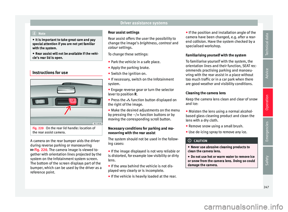
Fig. 220
On the rear lid handle: location of
the r e
ar a
ssist camera. A camera on the rear bumper aids the driver
durin
g r
ev
erse parking or manoeuvring
››› Fig. 220. The camera image is viewed to-
gether with orientation lines projected by the
system on the Infotainment system screen.
The bottom of the screen displays part of the
bumper, which can be used by the driver as a
reference point. Rear assist settings
Rear a
ssist offers the user the possibility to
change the image's brightness, contrast and
colour settings.
To change these settings:
● Park the vehicle in a safe place.
● Apply the parking brake.
● Switch the ignition on.
● If necessary, switch on the Infotainment
syst
em.
● Engage reverse gear or turn the selector
lever t
o position R.
● Press the function b
utton displayed on
the right of the image.
● Make the desired adjustments on the menu
by pr
essing the –/+ function buttons or by
moving the corresponding scroll button.
Necessary conditions for parking and ma-
noeuvring with the rear assist
The system should not be used in the follow-
ing cases:
● If the image displayed is not very reliable or
is di
storted, for example low visibility or dirty
lens.
● If the area behind the vehicle is not dis-
pla
yed very clearly or is incomplete.
● If the vehicle is heavily loaded at the rear. ●
If the pos
ition and installation angle of the
camera have been changed, e.g. after a rear-
end collision. Have the system checked by a
specialised workshop.
Familiarising yourself with the system
To familiarise yourself with the system, the
orientation lines and their function, SEAT rec-
ommends practising parking and manoeu-
vring with the rear assist in a place without
too much traffic or in a car park when there
are good weather and visibility conditions.
Cleaning the camera lens
Keep the camera lens clean and clear of snow
and ice:
● Moisten the lens using a normal alcohol-
based gl
ass cleaning product and clean the
lens with a dry cloth.
● Remove snow using a small brush.
● Use de-icing spray to remove any ice. CAUTION
● Never u se abr
asive cleaning products to
clean the camera lens.
● Do not use hot or warm water to remove ice
or snow fr
om the camera lens. Doing so could
damage the camera. 247
Technical data
Advice
Operation
Emergencies
Safety