technical data Seat Ateca 2016 Owners Manual
[x] Cancel search | Manufacturer: SEAT, Model Year: 2016, Model line: Ateca, Model: Seat Ateca 2016Pages: 328, PDF Size: 6.32 MB
Page 241 of 328
Driver assistance systems
Automatic braking intervention by
P ark
Assist Park Assist helps the driver by automatically
br
ak
ing in certain situations.
The driver is always responsible for braking
in time ››› .
Aut om
atic braking intervention to avoid ex-
ceeding the speed limit
To avoid exceeding the speed limit of approx-
imately 7 km/h (4 mph) when entering or
leaving a parking space, the brakes may acti-
vate automatically. After automatically acti-
vating the brakes, the manoeuvres to enter or
exit a parking space may continue.
The brakes are only automatically activated
once for each attempt to enter or exit a park-
ing space. If the speed of approximately
7 km/h (4 mph) is exceeded again, the corre-
sponding operation is halted.
Automatic braking to reduce damages
Depending on certain conditions, the Park
Assist system can automatically brake the ve-
hicle when faced with an obstacle, briefly ac-
tioning and holding down the brake ped-
al ››› . Following this the driver must press
the br ak
e pedal.
Automatic braking intervention to reduce
damage leads to the parking manoeuvre fin-
ishing. WARNING
The automatic braking intervention by Park
As s
ist should never tempt you to take any
risk that may compromise safety. The system
is not a replacement for driver awareness.
● The Park Assist system is subject to certain
limitation
s inherent to the system. In certain
situations, the automatic braking interven-
tion may only work in a limited way or not
work at all.
● Always be ready to use the brakes yourself!
● The automatic braking intervention will end
aft
er approximately 1.5 seconds. Following
this, brake the vehicle yourself. Parking System Plus (ParkPi-
lot)*
D e
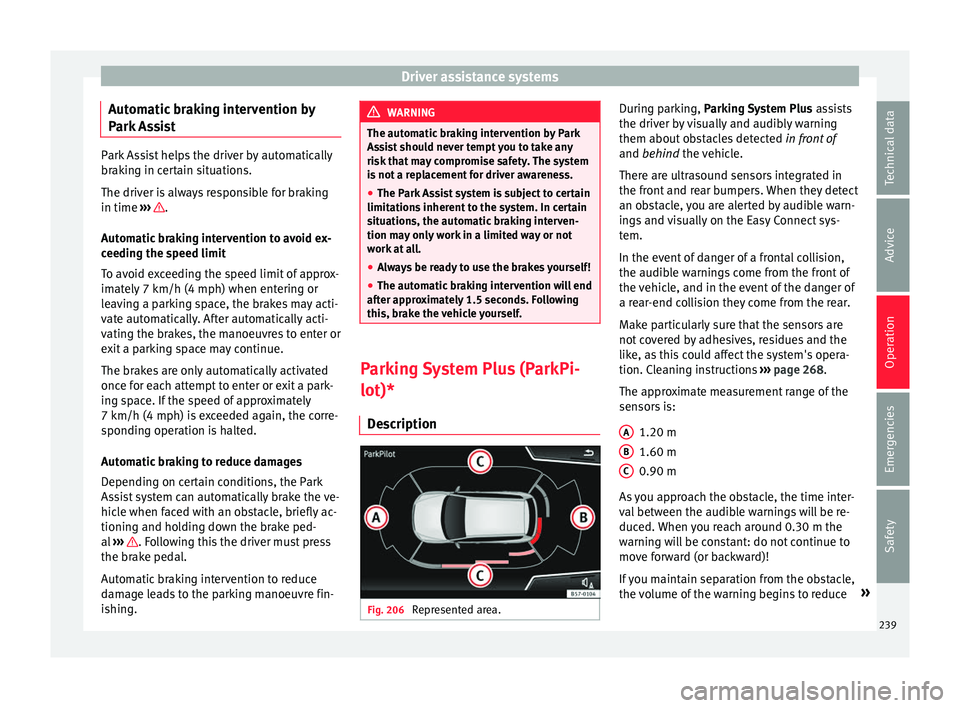
scription Fig. 206
Represented area. During parking, P
ark
ing System Plus assists
the driver by visually and audibly warning
them about obstacles detected in front of
and behind the vehicle.
There are ultrasound sensors integrated in
the front and rear bumpers. When they detect
an obstacle, you are alerted by audible warn-
ings and visually on the Easy Connect sys-
tem.
In the event of danger of a frontal collision,
the audible warnings come from the front of
the vehicle, and in the event of the danger of
a rear-end collision they come from the rear.
Make particularly sure that the sensors are
not covered by adhesives, residues and the
like, as this could affect the system's opera-
tion. Cleaning instructions ››› page 268.
The approximate measurement range of the
sensors is:
1.20 m
1.60 m
0.90 m
As you approach the obstacle, the time inter-
val between the audible warnings will be re-
duced. When you reach around 0.30 m the
warning will be constant: do not continue to
move forward (or backward)!
If you maintain separation from the obstacle,
the volume of the warning begins to reduce »
A B
C
239
Technical data
Advice
Operation
Emergencies
Safety
Page 243 of 328
Driver assistance systems
–
if the number p
late is not perfectly se-
cured to the bumper surface,
– or in locations such as the brow of a hill.
● In order to guarantee good system opera-
tion, keep the u
ltrasound sensors clean, free
of snow or ice, and do not cover them with
adhesives or other objects.
● If you use high-pressure or vapour equip-
ment t
o clean the ultrasound sensors, apply
it directly only very briefly and always from a
distance of more than 10 cm.
● Retrofitting of accessories to the vehicle,
suc
h as a bicycle rack, may interfere with the
operation of the Parking Aid.
● Fitting certain accessories to the front of
the v
ehicle, such as a plate holder with ad-
vertising, may interfere with the operation of
the Park Assist.
● In order to familiarise yourself with the sys-
tem, it
is advised that you practice parking in
an area or car park that is free from traffic.
There must be good weather and light condi-
tions.
● The volume and tone of the warnings can
be modified, in ad
dition to the indications
››› page 246.
● In vehicles without
an infotainment system,
these parameters can be modified in a SEAT
Official Service or in a specialised workshop.
● Please observe information on towing a
trai
ler ››› page 247.
● The display on the Easy Connect screen
show
s a slight time delay. Parking Aid operation
Fig. 207
Centre console: Park Assist button
(dependin g on the
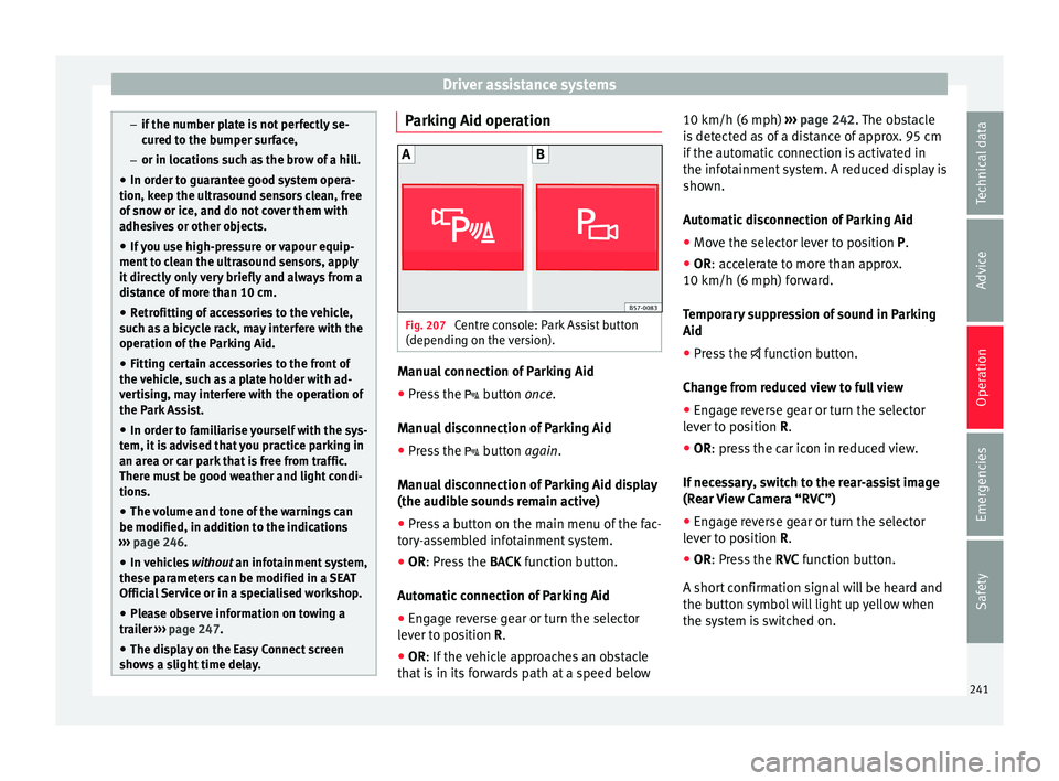
version). Manual connection of Parking Aid
● Press the butt
on once.
Manual disconnection of Parking Aid
● Press the butt
on again.
Manual disconnection of Parking Aid display
(the audible sounds remain active)
● Press a button on the main menu of the fac-
tor
y-assembled infotainment system.
● OR: Press the BACK f
unction button.
Automatic connection of Parking Aid ● Engage reverse gear or turn the selector
lev
er to position R.
● OR: If the vehicle approaches an obstacle
th
at is in its forwards path at a speed below 10 km/h (6 mph)
››
› page 242. The obstacle
is detected as of a distance of approx. 95 cm
if the automatic connection is activated in
the infotainment system. A reduced display is
shown.
Automatic disconnection of Parking Aid
● Move the selector lever to position P.
● OR: accelerate to more than approx.
10 km/h (6 mph) f
orward.
Temporary suppression of sound in Parking
Aid
● Press the fu
nction button.
Change from reduced view to full view
● Engage reverse gear or turn the selector
lev
er to position R.
● OR: press the car icon in reduced view.
If
necessary, switch to the rear-assist image
(Rear View Camera “RVC”)
● Engage reverse gear or turn the selector
lev
er to position R.
● OR: Press the RVC f
unction button.
A short confirmation signal will be heard and
the button symbol will light up yellow when
the system is switched on.
241
Technical data
Advice
Operation
Emergencies
Safety
Page 245 of 328
Driver assistance systems
Moreover, with the SEAT Media System
Plu s/Nav
i System radios, a yellow trail indi-
cates the vehicle's expected trajectory based
on the steering wheel angle.
Whenever the obstacle is located in the vehi-
cle’s direction of travel, the corresponding
audible warning will sound.
As the vehicle approaches an obstacle, the
segments are displayed closer to the vehicle.
When the penultimate segment is displayed,
this means that the vehicle has reached the
collision zone. In the collision zone, the ob-
stacles are represented in red, including
those out of the path. Do not continue to
move forward (or backward) ››› in Descrip-
tion on p ag
e 240, ››› in Description on
p ag
e 240 !
In the event the car is equipped with the Area
View system, visual indication of Park Assist
will appear depending on the selected view
in the Area View system.
Adjusting the display and audible
warnin
gs The settings for the display and audible
w
arnin
gs are controlled via the Easy Con-
nect*. Automatic activation
on – activat
es the Automatic activa-
tion option ››› page 242.
off – deactivates the Automatic ac-
tivation option ››› page 242.
Front volume*
Volume in the front and rear area.
Front sound settings/sharpness*
Frequency (tone) of the sound in the front
area.
Rear volume*
Volume in the rear area.
Rear sound settings/sharpness*
Frequency (tone) of the sound in the rear
area.
Adjust volume
With the parking aid switched on, the active
audio/video source volume will be reduced
to the intensity of the selected setting.
Error messages When the Parking Aid is activated or when it
i
s
switched on, if a message reporting a Park- ing aid error is displayed on the instrument
panel, ther
e is a fault in the system.
If the fault doesn't disappear before discon-
necting the ignition, next time that parking
aid is engaged in reverse, it will not be indi-
cated.
If there is a fault in the parking aid system a
message will appear on the instrument panel
indicating the error. In addition the key
LED will blink.
If there is a fault in a sensor, the symbol is
displayed on the Easy Connect display in
front of/behind the vehicle. If a rear sensor is
faulty, only the obstacles in the areas A and
B are displayed
››
› Fig. 206. If a front sensor
is faulty, only the obstacles in the areas C and
D are displayed.
Hav e the f
ault corrected by a specialised
workshop without delay.
243
Technical data
Advice
Operation
Emergencies
Safety
Page 247 of 328
Driver assistance systems
●
The u ltr
asound sensors have blind spots in
which obstacles and people are not regis-
tered. Pay special attention to children and
animals.
● Always keep visual control of the vehicle
surr
oundings: use the mirrors for additional
help. CAUTION
Parking Aid functions may be negatively af-
f ect
ed by different factors that may lead to
damage to the vehicle or its immediate sur-
rounds:
● Under certain circumstances, the system
does
not detect or display certain objects:
– Objects such as chains, trailer draw bars,
fences, posts and thin trees.
– Objects that are located above the sen-
sors, such as protrusions in a wall.
– Objects with certain surfaces or struc-
tures, such as wire mesh fences or pow-
der snow.
● Certain surfaces of objects and garments
do not r
eflect the ultrasound sensors' sig-
nals. The system cannot detect these objects
or people wearing such clothes correctly.
● Ultrasound sensor signals may be affected
by
external sound sources. In certain circum-
stances this may prevent them from detect-
ing people or objects.
● Please note that low obstacles detected by
the sys
tem may no longer be registered by the sensors as the car moves closer, so the
sy
s
tem will not give any further warning. In
certain circumstances, objects such as high
kerbs that could damage the bottom of the
vehicle are not detected either.
● If the first warning from the ParkPilot is ig-
nored, the
vehicle could suffer considerable
damage.
● The knocks or damage on the radiator
gril
le, bumper, wheel arch and vehicle under-
body can adjust the orientation of the sen-
sors. This can affect the parking aid function.
In this case, have the function checked by a
specialised workshop. Note
● In c er
tain situations, the system can give a
warning even though there is no obstacle in
the detected area, e.g:
–with rough or cobbled floors or ground
with long grass;
– with external ultrasound sources, such as
cleaning vehicles or other vehicles equip-
ped with ultrasound systems;
– in downpours, intense snow, hail or
dense exhaust gases,
– if the number plate is not perfectly se-
cured to the bumper surface,
– or in locations such as the brow of a hill.
● In order to guarantee good system opera-
tion, keep the u
ltrasound sensors clean, free of snow or ice, and do not cover them with
a
dhe
sives or other objects.
● If you use high-pressure or vapour equip-
ment t
o clean the ultrasound sensors, apply
it directly only very briefly and always from a
distance of more than 10 cm.
● Retrofitting of accessories to the vehicle,
suc
h as a bicycle rack, may interfere with the
operation of the Parking Aid.
● In order to familiarise yourself with the sys-
tem, it
is advised that you practice parking in
an area or car park that is free from traffic.
There must be good weather and light condi-
tions.
● The volume and tone of the warnings can
be modified, in ad
dition to the indications
››› page 246.
● In vehicles without
an infotainment system,
these parameters can be modified in a SEAT
Official Service or in a specialised workshop.
● Please observe information on towing a
trai
ler ››› page 247.
● The display on the Easy Connect screen
show
s a slight time delay. Parking Aid operation
Manual disconnection of Parking Aid display
(the audib
l
e sounds remain active)
● Press a button on the main menu of the fac-
t or
y-assembled infotainment system.
● OR: Pr ess the BACK f
unction button. »
245
Technical data
Advice
Operation
Emergencies
Safety
Page 249 of 328
Driver assistance systems
Rear sound settings/sharpness*
Fr equency
(tone) of the sound in the rear
area.
Adjust volume
With the parking aid switched on, the active
audio/video source volume will be reduced
to the intensity of the selected setting.
Error messages When the Parking Aid is activated or when it
i
s
switched on, if a message reporting a Park-
ing aid error is displayed on the instrument
panel, there is a fault in the system.
If the fault disappears before disconnecting
the ignition, next time that parking aid is en-
gaged in reverse it will not be indicated.
If there is a fault in a sensor, the symbol is
displayed on the Easy Connect display.
Have the fault corrected by a specialised
workshop without delay.
Towing bracket In vehicles equipped with a towing bracket
dev
ic
e from the factory, when the trailer is
connected electrically, the Parking Aid rear
sensors will not be activated when reverse
gear is engaged (manual gears) nor when the selector lever is turned to position
R (auto-
m
atic gears).
Area View* Introduction
› ›
›
table on page 2
Using 4 cameras, the system generates a rep-
resentation that is shown on the infotain-
ment system display. The cameras are loca-
ted on the radiator grille, the exterior mirrors
and the rear lid.
The functions and representations of the
Area View system may vary depending on
whether or not the vehicle has ParkPilot. WARNING
The image from the cameras does not make it
po s
sible to calculate the distance to the ob-
stacles (people, vehicles, etc.) precisely, so
using them could cause serious accidents
and injury.
● The camera lenses augment and distort the
vi
sual field and the objects on the screen are
seen differently and imprecisely.
● Certain objects may not be shown or may
not be sho
wn very clearly, for example, posts
or thin rails, due to the screen resolution or if
light conditions are insufficient. ●
The c amer
as have blind spots in which ob-
stacles and people are not registered.
● The camera lens must be kept free, without
sno
w or ice, and should not be covered. WARNING
The smart technology incorporated into the
Ar e
a View system cannot overcome the limits
imposed by the laws of physics and it only
works within the limits of the system. The
greater convenience provided by the Area
View system should never tempt you to take
any risk that may compromise safety. If used
negligently or involuntarily, it may cause se-
rious accidents and injuries. The system is
not a replacement for driver awareness.
● Adapt your speed and driving style to suit
vi
sibility, weather, road and traffic condi-
tions.
● Do not be distracted from the traffic by
lookin
g at the screen.
● Monitor the area around the vehicle at all
times, s
ince the cameras do not capture small
children, animals and certain objects in all
situations.
● The use of a number plate may interfere in
the v
iews shown on the screen, since the
cameras' field of vision may be reduced.
● The system will probably be unable to rep-
re
sent all areas clearly. » 247
Technical data
Advice
Operation
Emergencies
Safety
Page 251 of 328
Driver assistance systems
system should be checked by a specialised
w ork
shop.
Camera image view
● Aerial view (bird's eye view) : to o
btain a
panoramic view of the vehicle , three-di-
mensional views, from different camera posi-
tions.
● Front Camera (front view) : to o
bserve traffic
ahead of the vehicle (vehicles crossing) ,
for front parallel parking , when approach-
ing an obstacle and in off-road driving .
● Side cameras (side view) : to
view the area
close to the sides of the vehicle, both on the
left and on the right , or a combination of
both sides .
● Rear camera (rear view) : T
o observe traffic
behind the vehicle (vehicles crossing) , for
reverse perpendicular parking , for reverse
parallel parking and for hitching a trailer
to the vehicle .
The selected view is displayed on the right
side of the screen. The reduced aerial view
shown on the right side displays the view
framed in yellow. In addition, the right mar-
gin of the screen displays the menu options
possible and the views (the so-called
“modes”) of the camera in question. The ac-
tive view (mode) at the time is highlighted.
The reduced aerial view can be hidden by
pressing the symbol to thus display the se-
lected view full-screen. Instructions for use
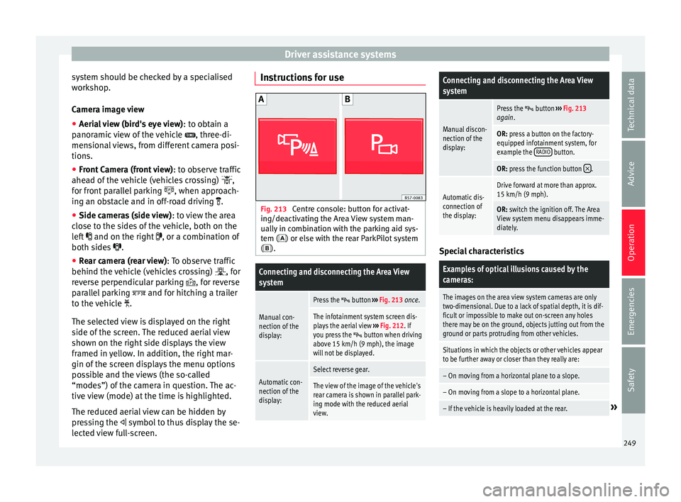
Fig. 213
Centre console: button for activat-
in g/de
activating the Area View system man-
ually in combination with the parking aid sys-
tem () or else with the rear ParkPilot system ().
Connecting and disconnecting the Area View
system
Manual con-
nection of the
display:
Press the button ››› Fig. 213 once.
The infotainment system screen dis-
plays the aerial view ››› Fig. 212. If
you press the
button when driving
above 15 km/h (9 mph), the image
will not be displayed.
Automatic con-
nection of the
display:
Select reverse gear.
The view of the image of the vehicle's
rear camera is shown in parallel park-
ing mode with the reduced aerial
view.
Connecting and disconnecting the Area View
system
Manual discon-
nection of the
display:
Press the button ››› Fig. 213
again.
OR: press a button on the factory-
equipped infotainment system, for
example the RADIO
button.
OR: press the function button .
Automatic dis-
connection of
the display:Drive forward at more than approx.
15 km/h (9 mph).
OR: switch the ignition off. The Area
View system menu disappears imme-
diately. Special characteristics
Examples of optical illusions caused by the
cameras:
The images on the area view system cameras are only
two-dimensional. Due to a lack of spatial depth, it is dif-
ficult or impossible to make out on-screen any holes
there may be on the ground, objects jutting out from the
ground or parts protruding from other vehicles.
Situations in which the objects or other vehicles appear
to be further away or closer than they really are:
– On moving from a horizontal plane to a slope.
– On moving from a slope to a horizontal plane.
– If the vehicle is heavily loaded at the rear.»
249
Technical data
Advice
Operation
Emergencies
Safety
Page 253 of 328
Driver assistance systemsViewOn-screen display of all cameras
Three-di-
mensional views
The vehicle and its vicinity seen
from above are shown.
The vehicle and its vicinity seen
from above are shown oblique-
ly.
The vehicle and its vicinity seen
obliquely are shown.
Swipe the infotainment system display with
y
our fin
ger in the direction of the arrows to
change the angle of vision in the three-di-
mensional views of the vehicle and its vicini-
ty.
Front camera views (front view)
ViewOn-screen display of the front
camera
Cross traffic at the front
Left area of the screen: street to the left.
Central area of the screen: area directly
in front of the vehicle.
Right area of the screen: street to the
right.
Parallel park- ing
The area in front of the vehicle is
shown. Orientation lines are shown to
give guidance.
ViewOn-screen display of the front
camera
Off-road
The area directly in front of the vehicle
seen from above is shown. For example,
on a slope, in order to see the area di-
rectly in front of the vehicle. The red line
is shown at a distance of approx. 0.4 m
from the vehicle. Side camera views (side view)
ViewOn-screen display of the side
cameras
Right and left
sides
The areas located directly to the side of
the vehicle seen from above are repre-
sented in order to navigate possible ob-
stacles more precisely. The orange aux-
iliary lines are shown at a distance of
approx. 0.4 m from the vehicle.
Left side
The area directly next to the vehicle, on
the driver's or front passenger's side, is
displayed, and the blind spots all along
the vehicle can be seen. The orange
auxiliary line is shown at a distance of
approx. 0.4 m from the vehicle.
Right side
Rear camera views (rear view)
ViewOn-screen display of the rear
camera
Parallel park-
ing
The area behind the vehicle is shown.
Auxiliary lines are shown to give guid-
ance.
Parallel park-ing
The vehicle's initial position on initiat-
ing this function will be a decisive fac-
tor in determining the place where the
manoeuvre executed by the assistant
will end.
Off-road orhitching a
trailer func- tion
The vehicle's rear is presented. The red
auxiliary line establishes the safety dis-
tance.
Green and red semicircular auxiliary
lines are displayed in vehicles with a
factory-fitted towing bracket. The auxili-
ary lines indicate the distance from the
towing bracket. The distance between
the auxiliary lines (green and red) is ap-
prox. 0.3 m. The orange auxiliary line in-
dicates, depending on the turn of the
steering wheel, the pre-calculated di-
rection of the towing bracket.
In vehicles with a factory-fitted towing
bracket, the distance from the red auxil-
iary line to the vehicle is approx. 0.4 m.
No other auxiliary line is displayed.
» 251
Technical data
Advice
Operation
Emergencies
Safety
Page 255 of 328
Driver assistance systems
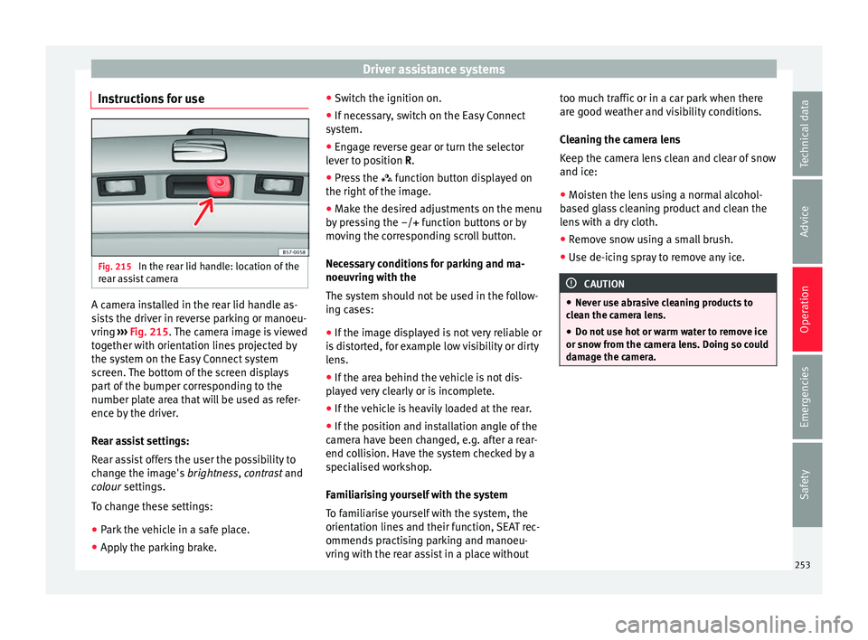
Instructions for use Fig. 215
In the rear lid handle: location of the
r e
ar assist camera A camera installed in the rear lid handle as-
s
i
sts the driver in reverse parking or manoeu-
vring ››› Fig. 215. The camera image is viewed
together with orientation lines projected by
the system on the Easy Connect system
screen. The bottom of the screen displays
part of the bumper corresponding to the
number plate area that will be used as refer-
ence by the driver.
Rear assist settings:
Rear assist offers the user the possibility to
change the image's brightness, contrast and
colour settings.
To change these settings:
● Park the vehicle in a safe place.
● Apply the parking brake. ●
Swit
ch the ignition on.
● If necessary, switch on the Easy Connect
sys
tem.
● Engage reverse gear or turn the selector
lev
er to position R.
● Press the fu
nction button displayed on
the right of the image.
● Make the desired adjustments on the menu
by
pressing the –/+ function buttons or by
moving the corresponding scroll button.
Necessary conditions for parking and ma-
noeuvring with the
The system should not be used in the follow-
ing cases:
● If the image displayed is not very reliable or
is
distorted, for example low visibility or dirty
lens.
● If the area behind the vehicle is not dis-
pl
ayed very clearly or is incomplete.
● If the vehicle is heavily loaded at the rear.
● If the position and installation angle of the
camer
a have been changed, e.g. after a rear-
end collision. Have the system checked by a
specialised workshop.
Familiarising yourself with the system
To familiarise yourself with the system, the
orientation lines and their function, SEAT rec-
ommends practising parking and manoeu-
vring with the rear assist in a place without too much traffic or in a car park when there
are g
ood weather and visibility conditions.
Cleaning the camera lens
Keep the camera lens clean and clear of snow
and ice:
● Moisten the lens using a normal alcohol-
ba
sed glass cleaning product and clean the
lens with a dry cloth.
● Remove snow using a small brush.
● Use de-icing spray to remove any ice. CAUTION
● Nev er u
se abrasive cleaning products to
clean the camera lens.
● Do not use hot or warm water to remove ice
or sno
w from the camera lens. Doing so could
damage the camera. 253
Technical data
Advice
Operation
Emergencies
Safety
Page 257 of 328
Towing bracket device*
Towing bracket device* T r
ailer mode
Introduction Take into account country-specific regula-
tion
s
about driving with a trailer and the use
of a towing bracket.
The vehicle has been developed primarily for
carrying people, although it can also be used
to tow a trailer if fitted with the correspond-
ing technical equipment. This additional load
has an effect on the useful life, fuel con-
sumption and vehicle performance and in
some cases can reduce the service intervals.
Driving with a trailer requires more force from
the vehicle, and thus more concentration
from the driver.
In winter, winter tyres should be fitted on
both the vehicle and the trailer.
Maximum vertical load technically permissi-
ble on the coupling
The maximum vertical load technically per-
mitted from the trailer draw bar on the towing
bracket's tow hitch is 85 kg.
Vehicles with the Start-Stop system
If the vehicle has a factory-fitted towing
bracket or one that is retrofitted by SEAT, the Start-Stop system operates as normal. No
s
pec
ial characteristics need to be taken into
account.
If the system does not recognise the trailer or
the trailer bracket has not been retrofitted by
SEAT, the Start-Stop system must be discon-
nected by pressing the corresponding button
in the lower part of the centre console before
driving with the trailer, and it should remain
off for the rest of the journey ››› .
V ehic
les with driving profile selection
If you are going to be towing a trailer, the use
of the Eco driving profile is not recommen-
ded. You are advised to select another of the
available driving profiles before beginning to
drive with a trailer. WARNING
Never use the trailer to transport people,
s inc
e it would put their life in danger and is
also prohibited. WARNING
Undue use of the towing bracket may cause
injur y
and accidents.
● Only use the towing bracket if it is in a per-
fect
state of repair and is properly secured.
● Never modify or repair the towing bracket
in any
way.
● In order to reduce the danger of injury in
the event
of rear-end collisions and to avoid injury to pedestrians and cyclists when park-
in
g the
vehicle, cover or remove the tow hitch
when you are not using a trailer.
● Never fit a towing bracket “with weight dis-
tribution” or “lo
ad compensation”. The vehi-
cle has not been designed for this type of
towing bracket. The towing bracket could fail
and the trailer could be released from the ve-
hicle. WARNING
Driving with a trailer and transporting heavy
or l ar
ge objects can affect driving properties
and even cause an accident.
● Always secure the load properly using belts
or str
aps that are suitable and in good condi-
tion.
● Adapt your speed and driving style at all
times
to suit visibility, weather, road and traf-
fic conditions.
● Trailers with a high centre of gravity are
more lik
ely to overturn than those with a low
one.
● Avoid sudden braking and manoeuvres.
● Take great care when overtaking.
● Reduce speed immediately if you notice
that
the trailer is swaying, however slightly.
● Never drive at more than 80 km/h (50 mph)
when to
wing a trailer (or at more than
100 km/h (60 mph) in exceptional circum-
stances). This also applies in countries where
driving at higher speeds is permitted. Take » 255
Technical data
Advice
Operation
Emergencies
Safety
Page 259 of 328
Towing bracket device*
Trailer brakes
If the tr
ailer has its own brake system, please
take the relevant legal requirements into ac-
count. Never connect the trailer's brake sys-
tem to the vehicle's brake system.
Tow rope
Always use a cable between the vehicle and
the trailer ››› page 259.
Trailer rear lights
The trailer's rear lights should comply with
the statutory safety regulations ››› page 259.
Never connect the trailer's rear lights directly
to the vehicle's electric system. If you are not
sure that the trailer's electrical connection is
correct, have it checked by a specialised
workshop. SEAT recommends visiting a SEAT
dealership for this.
Exterior mirrors
If you cannot see the area behind the trailer
with the exterior mirrors of the towing vehi-
cle, additional mirrors will have to be instal-
led in accordance with the regulations of the
country in question. The exterior mirrors
should be adjusted before you start driving
and must provide a sufficient field of vision
at the rear. Trailer maximum electricity consumption
ConsumersEurope, Asia,
Africa, South America and
Central AmericaAustralia
Brake lights (total)84 Watts108 Watts
Turn signal (on each
side)42 Watts54 Watts
Side lights (on each
side)50 Watts100 Watts
Reverse lights (on
each side)42 Watts54 Watts
Rear fog light42 Watts54 Watts
Never exceed the values indicated! WARNING
If the towing bracket is wrongly fitted or is
not the right
one, the trailer could become
detached from the vehicle and cause serious
injury. CAUTION
● If the r
ear lights of the trailer are not cor-
rectly connected, the vehicle's electronic sys-
tem may be damaged.
● If the trailer absorbs excessive electric cur-
rent, the
vehicle's electronic system may be
damaged. ●
Nev er c
onnect the trailer's electric system
directly to the electrical connections of the
tail lights or any other power sources. Only
use the connections intended for providing
electric current to the trailer. Electrical unlocking tow hitch
Fig. 217
On the right side of the luggage
c omp
artment: button for unlocking the tow
hitch.
› ›
›
table on page 2
The tow hitch is located in the bumper. The
electrical unlocking tow hitch cannot be dis-
assembled.
There should be no person, animal or object
in the path of the tow hitch ››› .
»
257
Technical data
Advice
Operation
Emergencies
Safety