technical data Seat Ateca 2016 Repair Manual
[x] Cancel search | Manufacturer: SEAT, Model Year: 2016, Model line: Ateca, Model: Seat Ateca 2016Pages: 328, PDF Size: 6.32 MB
Page 181 of 328
Driving
Note
● If the sel
ector lever lock does not engage,
there is a fault. The transmission is interrup-
ted to prevent the vehicle from accidentally
moving. Follow the procedure below in order
for the selector lever lock to engage again:
–With a 6-speed gearbox: press the brake
pedal and release it again.
– With a 7-speed gearbox: press the brake
pedal. Move the selector lever to posi-
tion P or N and subsequently engage a
gear.
● Despite a gear being engaged, the vehicle
does
not move forwards or back. Proceed to
the next mode:
– When the vehicle does not move in the
required direction, the system may not
have the gear range correctly engaged.
Press the brake pedal and engage the
gear range again.
– If the vehicle still does not move in the
required direction, there is a system mal-
function. Seek specialist assistance and
have the system checked. Changing gears in tiptronic mode*
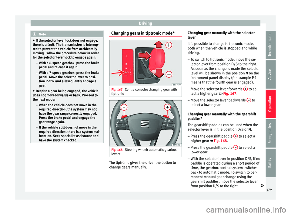
Fig. 167
Centre console: changing gear with
tiptr onic Fig. 168
Steering wheel: automatic gearbox
l ev
ers The tiptronic gives the driver the option to
c
h
ange gears manually. Changing gear manually with the selector
lev
er
It is possible to change to tiptronic mode,
both when the vehicle is stopped and while
driving.
– To switch to tiptronic mode, move the se-
lect
or lever from position D/S to the right.
As soon as the change is made the selector
level will be shown in the position M on the
instrument panel display (for example M4
means that the fourth gear is engaged).
– Move the selector lever forwards + to se-
l ect
a higher gear ››› Fig. 167.
– Move the selector lever backwards – to
sel ect
a lower gear.
Changing gear manually with the gearshift
paddles*
The gearshift paddles can be used when the
selector lever is in the position D/S or M.
– Press the gearshift paddle + to select a
higher g e
ar ››› Fig. 168.
– Press the gearshift paddle – to select a
lo w
er gear.
– With the selector lever in position D/S, if no
pa
ddle is operated during a short period of
time, the gearbox control system switches
back to automatic mode. To switch to per-
manent manual gear change using the
gearshift paddles, move the selector lever
from position D/S to the right. »
179
Technical data
Advice
Operation
Emergencies
Safety
Page 183 of 328
Driving
damage the automatic gearbox. Apply the
h
andbr
ake firmly or press the brake pedal in
order to prevent the vehicle from rolling back.
● If you allow the car to roll with the selector
lev
er in position N with the engine switched
off, the automatic gearbox will be damaged
as it will not be lubricated.
● In certain driving situations or traffic condi-
tions, s
uch as frequently starting, prolonged
“creeping” of the vehicle or traffic jams with
continuous stoppages, the gearbox could
overheat causing damage! If the warning
lamp lights up, stop the vehicle as soon as
possible and wait for the gearbox to cool
››› page 183. Kick-down feature
The kick-down feature allows maximum ac-
c
el
eration to be reached.
When the accelerator pedal is pressed right
down past the point of resistance at full throt-
tle, the gearbox will shift down to a lower
gear, depending on road speed and engine
speed. The upshift to the next higher gear is
delayed until the engine reaches maximum
rpm. WARNING
Please note that if the road surface is slip-
per y
or wet, the kick-down feature could
cause the driving wheels to spin, which could
result in skidding. Launch control programme
3
Valid for vehicles: with Launch-Control/6-Speed
D
SG with diesel engines superior to 125 kW and pet-
rol engines superior to 140 kW.
The Launch control programme enables maxi-
mum acceleration.
Important: the engine must have reached op-
erating temperature and the steering wheel
must not be turned.
The engine speed for launch-control is differ-
ent on petrol and diesel engines. To use the
launch-control you must disconnect the anti-
slip regulation (ASR) through the Easy Con-
nect system menu ›››
page 108. The warning
lamp will stay switched on or will flash
slowly depending on whether or not the vehi-
cle has a driver information system*.
On vehicles with the driver information sys-
tem, the ESC lamp lights up permanently and
the corresponding text message Stabilitycontrol deactivated
(tempor
ary) ap-
pears on the instrument panel to indicate the
deactivation status.
– When the engine is running, switch off the
traction c
ontrol (ASR) 1)
.
– Turn the selector lever to the position “S”
or tiptronic, or el
se select the sport driv-
ing mode from the SEAT Drive Profile*
››› page 225.
– Press the brake pedal firmly with your left
foot
and hold it down for at least one sec-
ond.
– With your right foot, press the accelerator
down t
o the full throttle or kick-down posi-
tion. The engine speed will stabilise at
about 3,200 rpm (petrol engine) or about
2,000 rpm (diesel engine).
– Take your left foot off the brake pedal. WARNING
● Alw
ays adapt your driving style to the traf-
fic conditions.
● Only use the launch control programme
when ro
ad and traffic conditions permit, and
make sure your manner of driving and accel-
erating the vehicle does not inconvenience or
endanger other road users. »1)
Vehicles without driver information system: the
w arnin
g lamp flashes slowly/Vehicles with driver in-
formation system: the warning lamp stays on. 181
Technical data
Advice
Operation
Emergencies
Safety
Page 185 of 328
Driving
WARNING
● If the iner
tia mode has been switched on,
take into account, when approaching an ob-
stacle and releasing the accelerator pedal,
that the vehicle will not decelerate in the usu-
al manner: risk of accident!
● When using inertia mode while travelling
down hi
lls, the vehicle can increase speed:
risk of accident!
● If other users drive your vehicle, warn them
about iner
tia mode. Note
● Iner ti
a mode is only available in eco (SEAT
Drive Profile*) driving mode.
● The driver message Inertia is
only dis-
played with the current consumption. In iner-
tia mode the gear will no longer be displayed
(for example “E” will appear instead of “E7”).
● On downhill sections with gradients above
15 %, the inerti
a mode will automatically be
switched off temporarily. Backup programme
A backup programme is in place if a fault
shou
l
d occur in the control system.
If all the positions of the selector lever are
shown over a light background on the instru-
ment panel display, there is a system fault
and the automatic gearbox will operate in with the backup programme. When the back-
up progr
amme is activated, it is possible to
drive the vehicle, however, at low speeds and
within a selected range of gears. In some ca-
ses driving in reverse gear may not be possi-
ble. CAUTION
If the gearbox operates with the backup pro-
gr amme, t
ake the vehicle to a specialised
workshop and have the fault repaired without
delay. Clutch
Clutch overheating! Please
stop!
The c
lutch has overheated and could be dam-
aged. Stop the vehicle and wait for the gear-
box to cool with the engine at idling speed
and the selector lever in position P. When the
warning lamp and the driver message switch
off, have the fault corrected by a specialised
workshop without delay. If the warning lamp
and the driver message do not switch off, do
not continue driving. Seek specialist assis-
tance. Gearbox malfunctions Gearbox: Fault! Stop the ve-
hicle and place the lever in the
position P.
Ther e i
s a fault in the gearbox. Stop the vehi-
cle in a safe place and do not continue driv-
ing. Seek specialist assistance.
Gearbox: System fault! You
may continue driving.
Have the fault corrected by a specialised
workshop without delay. Gearbox: System fault! You
can continue driving with re-
strictions. Reverse gear disa‐
bled
Take the vehicle to a specialised workshop
and have the fault repaired without delay. Gearbox: System fault! You
can continue driving in D until
switching off the engine
Stop the vehicle in a safe place well away
from moving traffic. Seek specialist assis-
tance. Gearbox: too hot. Adapt your
driving accordingly
Continue driving at moderate speeds. When
the warning lamp switches off, you can con-
tinue driving in a normal manner. »
183
Technical data
Advice
Operation
Emergencies
Safety
Page 187 of 328
Driving
Economical and environmentally-
friendly driv
ingFuel consumption, environmental pollution
and w
e
ar to the engine, brakes and tyres de-
pends largely on driving style. Fuel consump-
tion can be reduced by 10-15% with an eco-
nomical driving style and proper anticipation
of traffic conditions. The following section
gives you some tips on lessening the impact
on the environment and reducing your oper-
ating costs at the same time.
Active cylinder management (ACT ®
)*display
Depending on vehicle equipment, the active
cylinder management (ACT ®
) may automati-
cally deactivate some of the engine cylinders
if the driving situation does not require too
much power. When it is switched off, no fuel
is injected into these cylinders, hence total
fuel consumption may be reduced. The num-
ber of active cylinders can be seen on the in-
strument panel display ›››
page 30.
Foresight when driving
Acceleration causes the vehicle to consume
more fuel. If you think ahead when driving,
you will need to brake less and thus acceler-
ate less. Wherever possible, let the car roll
slowly to a stop, with a gear engaged (for in-
stance when you can see that the next traffic
lights are red). This takes advantage of the
engine braking effect, reducing wear on the brakes and tyres. Emissions and fuel con-
s
umption w
ill drop to zero due to the overrun
fuel cut-off.
Changing gear to save energy
An effective way of saving is to change in ad-
vance to a higher gear. Running the engine at
high rpm in the lower gears uses an unneces-
sary amount of fuel.
Manual gearbox : shift up from first to second
gear as soon as possible. In any case, we rec-
ommend that you change to a higher gear
upon reaching 2,000 rpm. Choosing the right
gear enables fuel savings. Select the highest
possible gear appropriate for the driving sit-
uation (the engine should continue function-
ing with cyclical regularity).
Automatic gearbox : accelerate gradually and
without reaching the “kick-down” position.
Avoid driving at high speed
Avoid travelling at top speed, whenever pos-
sible. Fuel consumption, emission of harmful
gases and noise pollution multiply dispropor-
tionately as speed is increased. Driving at
moderate speeds will help to save fuel.
Reduce idling time
In vehicles with the Start-Stop system idling
is automatically reduced. In vehicles without
the Start-Stop system it is worth switching off
the engine, for example, at level crossings and at traffic lights that remain red for long
periods
of time. When an engine has reached
operating temperature, and depending on
the cylinder capacity, keeping it switched off
for a minimum of about 5 seconds already
saves more than the amount of fuel necessa-
ry for restarting.
The engine takes a long time to warm up
when it is idling. Mechanical wear and pollu-
tant emissions are also especially high dur-
ing this initial warm-up phase. It is therefore
best to drive off immediately after starting
the engine. Avoid running the engine at high
speed.
Regular maintenance
Regular servicing helps in saving fuel even
before the engine is started. A well-serviced
engine gives you the benefit of improved fuel
efficiency as well as maximum reliability and
an enhanced resale value. A badly serviced
engine can consume up to 10% more fuel
than necessary.
Avoid short journeys
The engine and catalytic converter need to
reach their optimal operating temperature in
order to minimise fuel consumption and
emissions.
A cold engine consumes a disproportionate
amount of fuel. The engine reaches its work-
ing temperature after about four kilometres »
185
Technical data
Advice
Operation
Emergencies
Safety
Page 189 of 328
Driving
(automatic gearbox: gear S). Maintain the en-
gine s peed at
approximately 2,000 rpm. The
rise in temperature causes the soot on the fil-
ter to burn. On completion of the cleaning
the warning lamp will switch off. If the warn-
ing lamp does not switch off, go immediately
to a specialised workshop to rectify the prob-
lem.
Engine management* This warning lamp monitors the engine man-
ag
ement
system for petrol engines.
The warning lamp (Electronic Power Con-
trol) lights up when the ignition is switched
on while system operation is being verified. It
should go out once the engine is started.
If there is a fault in the electronic engine
management system while you are driving,
this warning lamp will light up. Take the vehi-
cle to a specialised workshop as soon as
possible and have the engine checked.
Emission control system* Control lamp
fla
shes:
When there is misfiring that can damage the
catalytic converter. Reduce speed and drive
carefully to the nearest specialised workshop
to have the engine checked. The control lamp
lights
up:
If a fault has developed during driving which
has reduced the quality of the exhaust gas
(e.g. lambda probe fault). Reduce speed and
drive carefully to the nearest specialised
workshop to have the engine checked.
Engine pre-heating/fault system* The warning lamp lights up to show that the
glo
w p
lugs are preheating the diesel engine.
The control lamp lights up
If the control lamp lights up when the en-
gine is started it means that the glow plugs
are preheating. The engine can be started
straight away when the lamp switches off.
Control lamp flashes
If a fault develops in the engine management
system while you are driving, the glow plug
system lamp will flash . Take the vehicle to
a specialised workshop as soon as possible
and have the engine checked. Driving tips
Driv in
g on flooded roads To prevent damage to the vehicle when driv-
in
g thr
ough water, for example, along a floo-
ded road, please observe the following:
● The water should never come above the
low
er edge of the bodywork.
● Drive at pedestrian speed. WARNING
After driving through water, mud, sludge,
et c
., the braking effect can be delayed slight-
ly due to moisture build-up on the discs and
brake pads. Applying the brakes carefully
several times will remove the moisture and
restore the full braking effect. CAUTION
● Driv in
g through flooded areas may severely
damage vehicle components such as the en-
gine, transmission, running gear or electrical
system.
● Whenever driving through water, the Start-
Stop sy
stem* must be switched off
››› page 188. Note
● Chec k
the depth of the water before enter-
ing the flooded zone. » 187
Technical data
Advice
Operation
Emergencies
Safety
Page 191 of 328
Driver assistance systems
– When the c lut
ch pedal is pressed the en-
gine will start up again. The warning lamp
will switch off.
Vehicles with an automatic gearbox
– Use the foot brake to bring the vehicle to a
st
op and keep the brake pedal pressed
down with your foot. The engine will switch
off. The warning lamp will appear in the
display.
– When you take your foot off the brake pedal
the engine w
ill start up again. The warning
lamp will switch off.
Additional information related to the auto-
matic gearbox
The engine stops when the selector lever is in
the positions P, D, N and S, in addition to
when in manual mode. With the selector lev-
er in position P, the engine will also remain
switched off when you take your foot off the
brake pedal. In order to start the engine up
again the accelerator must be pressed, or an-
other gear engaged or the brake released.
If the selector lever is placed in position R
during the stopping phase, the engine will
start up again.
Change from position D to P to prevent the
engine from accidentally starting when
changing and passing by position R. Note
● You c
an control whether the engine should
switch off or not by reducing or increasing the
brake force applied. While the vehicle re-
mains stopped, the engine will not stop if the
brake pedal is slightly pressed, in traffic jams
with frequent stopping and starting for exam-
ple. As soon as strong pressure is applied to
the brake pedal, the engine will stop.
● In vehicles with manual gearbox, during
the st
opping phases the brake pedal must re-
main depressed to prevent the vehicle from
moving.
● If the engine “stalls” in vehicles with man-
ual
gearbox, it can be directly started up
again by immediately pressing the clutch
pedal. General notes
The system can interrupt the Start-Stop mode
fr
equently
for different reasons.
The engine does not switch off
Before the stopping phase, the system veri-
fies whether certain conditions are met. The
engine does not switch off, in the following
situations for example:
● The engine has not yet reached the mini-
mum requir
ed temperature for the Start-Stop
mode. ●
The interior t
emperature selected for the air
conditioner has not yet been reached.
● The interior temperature is very high/low.
● Defrost function button activated
››
› page 42.
● The parking aid* is switched on.
● The battery is very low.
● The steering wheel is overly turned or is be-
ing t
urned.
● If there is a danger of misting.
● After engaging reverse gear.
● In case of a very steep gradient.
The indication i
s shown on the instrument
panel display, and in addition, the driver in-
formation system* shows, .
The engine starts by itself
During a stopping phase the normal Start-
Stop mode can be interrupted in the follow-
ing situations: The engine restarts by itself
without involvement from the driver.
● The interior temperature differs from the
value sel
ected on the air conditioner.
● Defrost function button activated
››
› page 42.
● The brake has been pressed several times
con
secutively.
● The battery is too low.
● High power consumption. »
189
Technical data
Advice
Operation
Emergencies
Safety
Page 193 of 328
Driver assistance systems
● The s lope of
the descent is at least 10%
when driving forward and 9% when driving in
reverse.
● The brake and the accelerator are not
pre
ssed.
Hill Descent Control is deactivated on press-
ing the brake and the accelerator or if the
slope is below 5%. The function may be dis-
connected manually in the Easy Connect sys-
tem by pressing the button and the
HDCfunction button
››
›
Fig. 41.
Control lamps
››› in Warning and control lamps on
p ag
e 107.
It lights up white
Hill Descent Control is active.
It lights up grey
Hill Descent Control is not active. The system is switched
on, but is not adjusting.
Some warning and control lamps will light up
briefly
when the ignition i
s switched on to
check certain functions. They will switch off
after a few seconds. WARNING
Observe the safety warnings ››
› in Warning
and c ontr
ol lamps on page 107. WARNING
Always be ready to brake. Otherwise, an acci-
dent c
ould occur and cause injury.
● Hill Descent Control is only an auxiliary
sys
tem that in some situations may not suffi-
ciently brake the vehicle when going down a
slope.
● The speed of the vehicle may increase de-
spit
e the intervention of Hill Descent Control. Auto Hold Function
D e
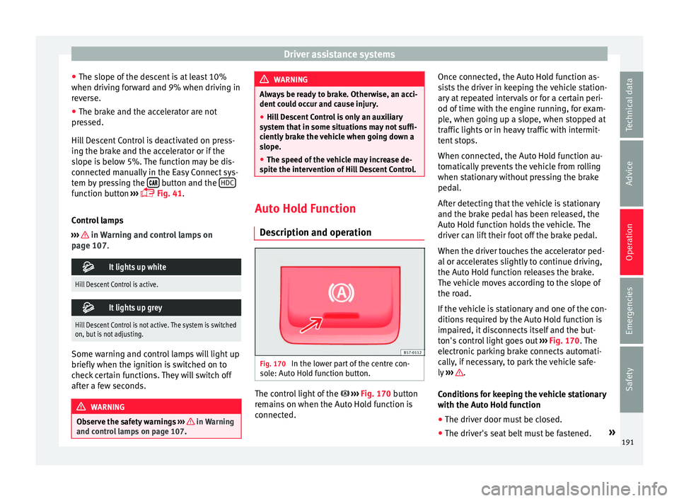
scription and operation Fig. 170
In the lower part of the centre con-
so l
e: Auto Hold function button. The control light of the
› ›
›
Fig. 170 button
remains on when the Auto Hold function is
connected. Once connected, the Auto Hold function as-
si
sts the driver in keeping the vehicle station-
ary at repeated intervals or for a certain peri-
od of time with the engine running, for exam-
ple, when going up a slope, when stopped at
traffic lights or in heavy traffic with intermit-
tent stops.
When connected, the Auto Hold function au-
tomatically prevents the vehicle from rolling
when stationary without pressing the brake
pedal.
After detecting that the vehicle is stationary
and the brake pedal has been released, the
Auto Hold function holds the vehicle. The
driver can lift their foot off the brake pedal.
When the driver touches the accelerator ped-
al or accelerates slightly to continue driving,
the Auto Hold function releases the brake.
The vehicle moves according to the slope of
the road.
If the vehicle is stationary and one of the con-
ditions required by the Auto Hold function is
impaired, it disconnects itself and the but-
ton's control light goes out ››› Fig. 170. The
electronic parking brake connects automati-
cally, if necessary, to park the vehicle safe-
ly ››› .
C ondition
s for keeping the vehicle stationary
with the Auto Hold function
● The driver door must be closed.
● The driver's seat belt must be fastened. »
191
Technical data
Advice
Operation
Emergencies
Safety
Page 195 of 328
Driver assistance systems
Cruise control system (CCS)* Oper ation Fig. 171
Instrument panel display: CCS status
indic ation
s Read the additional information carefully
› ›
› page 36
The cruise control system (CCS) is able to
maintain the set speed from 20 km/h (15
mph).
The CSS only reduces vehicle speed by ceas-
ing to accelerate, not by actively braking the
vehicle ››› .
C ontr
ol lamp
When the warning lamp is lit, cruise con-
trol is active. Several warning and control lamps light up
for a f
ew seconds when the ignition is switch-
ed on, signalling that the function is being
verified. They will switch off after a few sec-
onds.
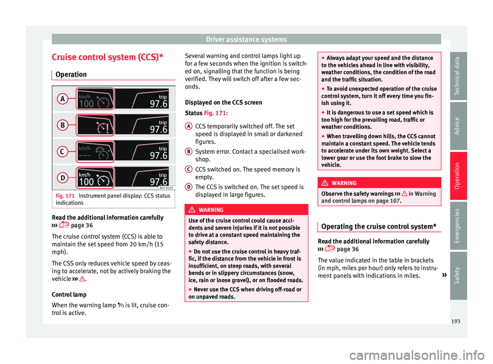
Displayed on the CCS screen
Status Fig. 171:
CCS temporarily switched off. The set
speed is displayed in small or darkened
figures.
System error. Contact a specialised work-
shop.
CCS switched on. The speed memory is
empty.
The CCS is switched on. The set speed is
displayed in large figures. WARNING
Use of the cruise control could cause acci-
dent s
and severe injuries if it is not possible
to drive at a constant speed maintaining the
safety distance.
● Do not use the cruise control in heavy traf-
fic, if the di
stance from the vehicle in front is
insufficient, on steep roads, with several
bends or in slippery circumstances (snow,
ice, rain or loose gravel), or on flooded roads.
● Never use the CCS when driving off-road or
on unp
aved roads. A
B
C
D ●
Alw
ays adapt your speed and the distance
to the vehicles ahead in line with visibility,
weather conditions, the condition of the road
and the traffic situation.
● To avoid unexpected operation of the cruise
contr
ol system, turn it off every time you fin-
ish using it.
● It is dangerous to use a set speed which is
too high f
or the prevailing road, traffic or
weather conditions.
● When travelling down hills, the CCS cannot
maint
ain a constant speed. The vehicle tends
to accelerate under its own weight. Select a
lower gear or use the foot brake to slow the
vehicle. WARNING
Observe the safety warnings ››
› in Warning
and c ontr
ol lamps on page 107. Operating the cruise control system*
Read the additional information carefully
› ›
› page 36
The value indicated in the table in brackets
(in mph, miles per hour) only refers to instru-
ment panels with indications in miles. »
193
Technical data
Advice
Operation
Emergencies
Safety
Page 197 of 328
Driver assistance systems
●
When driv in
g downhill, the speed limiter
cannot limit the vehicle speed. Its speed will
increase due to its own weight. In this case,
select a lower gear or use the foot brake to
slow the vehicle. WARNING
Observe the safety warnings ›
›
› in Warning
and c ontr
ol lamps on page 107. Note
● Diff er
ent versions of the instrument panel
are available and therefore the versions and
instructions on the display may vary.
● If when switching the ignition off, the
crui
se control system (CCS), the adaptive
cruise control (ACC) or the speed limiter were
switched on, then the cruise control system or the adaptive cruise control will automati-
c
a
lly switch themselves on when the ignition
is back on. However, no speed will be stored.
The last set speed of the speed limiter will be
stored. Operate the speed limiter
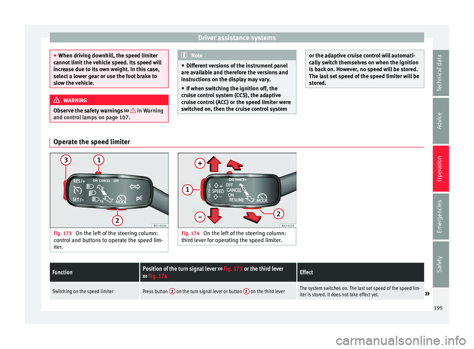
Fig. 173
On the left of the steering column:
c ontr
ol and buttons to operate the speed lim-
iter. Fig. 174
On the left of the steering column:
thir d l
ever for operating the speed limiter.
FunctionPosition of the turn signal lever ››› Fig. 173 or the third lever
››› Fig. 174Effect
Switching on the speed limiterPress button 2 on the turn signal lever or button 2 on the third leverThe system switches on. The last set speed of the speed lim-
iter is stored. It does not take effect yet.» 195
Technical data
Advice
Operation
Emergencies
Safety
Page 199 of 328
Driver assistance systemsFunctionPosition of the turn signal lever
››› Fig. 173 or the third lever
››› Fig. 174Effect
Switching off the speed limiterMove control 1 of the turn signal lever into position or the third lever
into position .The system switches off. The set speed will be stored. The values shown in the table in brackets, in
mph, ar
e di
splayed only in instrument panels
with indications in miles.
Going down slopes with the speed limiter
If the set speed of the speed limiter is excee-
ded while driving downhill, soon afterwards
the warning and control lamps flash
››› page 194 and an acoustic warning may
sound. In this case, use the foot brake to
slow the vehicle or, if necessary, select a low-
er gear.
Switching off temporarily
If you wish to temporarily switch off the
speed limiter, e.g. to overtake, move control
››› Fig. 173 1 of the turn signal lever into po-
s ition
or the third lever into pressure
point or press button 2 on any lever.
Af t
er overtaking, the speed limiter can be
switched on with the previously set speed by
pressing button 3 on the turn signal lever in
the ar e
a or by moving the third lever in-
to pressure point . Switch the speed limiter off temporarily by
pre
ssing down the accelerator (kick-down)
If the accelerator is pressed right down (kick-
down) and the set speed is exceeded be-
cause driver wishes to do so, the limiter is
temporarily disabled.
To confirm it being switched off an acoustic
signal sound once. While the limiter is off,
the warning and control lamp flashes.
When the accelerator is no longer pressed
down and the speed is reduced below the set
value, the limiter switches on again. The con-
trol lamp will light up and remain lit.
Automatic off
The speed limiter is automatically switched
off:
● If the system detects a fault that could neg-
atively
affect the working order of the limiter.
● If the airbag is triggered. CAUTION
For automatic switching off due to system
f ai
lures, for security reasons, the limiter is
only completely switched off when the driver stops pressing the accelerator at some point
or c
on
sciously switches off the system. Adaptive Cruise Control ACC*
Intr oduction Fig. 175
Detection area.
›
›
›
table on page 2
The adaptive cruise control (ACC) is an exten-
sion of the normal cruise control system
(CCS) ››› .
The A C
C function allows the driver to estab-
lish a cruise speed of between 30 and 210 »
197
Technical data
Advice
Operation
Emergencies
Safety