check engine Seat Ateca 2017 User Guide
[x] Cancel search | Manufacturer: SEAT, Model Year: 2017, Model line: Ateca, Model: Seat Ateca 2017Pages: 328, PDF Size: 6.36 MB
Page 159 of 328
Air conditioning
WARNING
Reduced visibility through the windows in-
c r
eases the risk of serious accidents.
● Always ensure that all windows are free of
ice and s
now, and that they are not fogged,
so as to maintain good visibility of everything
outside.
● The maximum heat output required to de-
fro
st windows as quickly as possible is only
available when the engine has reached its
normal running temperature. Only drive when
you have good visibility.
● Always ensure that you use the heating
sys
tem, fresh air system, air conditioner and
the heated rear window to maintain good visi-
bility to the outside.
● Never leave the air recirculation on for a
long period of
time. If the cooling system is
switched off and air recirculation mode
switched on, the windows can mist over very
quickly, considerably limiting visibility.
● Switch air recirculation mode off when it is
not r
equired. WARNING
Stuffy or used air will increase fatigue and re-
duc e driv
er concentration possibly resulting
in a serious accident.
● Never leave the fresh air fan turned off or
use the air r
ecirculation for long periods of
time; the air in the vehicle interior will not be
refreshed. CAUTION
● To r
eplace the pollen filter, always visit a
service centre.
● Switch the air conditioner off if you think it
ma
y be broken. This will avoid additional
damage. Have the air conditioner checked by
a specialised workshop.
● Repairs to the air conditioner require spe-
ci
alist knowledge and special tools. SEAT rec-
ommends visiting a SEAT Official Service. Note
● When the c oo
ling system is turned off, air
coming from the outside will not be dried. To
prevent fogging of the windows, SEAT recom-
mends leaving the cooling system (compres-
sor) turned on. To do this, press the button . The button lamp should light up.
● The maximum heat output required to de-
fr o
st windows as quickly as possible is only
available when the engine has reached its
normal running temperature.
● Keep the air intake slots in front of the
wind
screen free of snow, ice and leaves to en-
sure heating and cooling are not impaired,
and to prevent the windows from misting
over. Adjust using the Easy Connect sys-
t
em* 3 Ap
plies to vehicles with a Touch/Colour Media
S
ystem.
In the Easy Connect system it is also possible
to perform various adjustments to the Clima-
tronic.
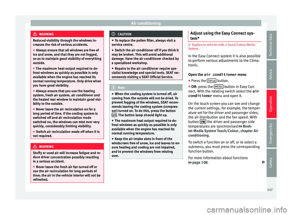
Open the air conditioner menu
● Press the Setup button.
● OR: pr ess the MENU button in Easy Con-
nect .
With the rotating switch select the air
conditioner menu and open it.
On the touch screen you can see and change
the current settings, for example, the temper-
ature set for the driver and passenger sides,
the air distribution and the fan speed. With
button the driver and passenger side
t emper
atures are synchronised ›››
Book-
let Media System Touch/Colour, chapter Air
conditioning.
To switch a function on or off, or to select a
submenu, you must press the corresponding
function button.
For more information about functions
››› page 108. »
157
Technical data
Advice
Operation
Emergencies
Safety
Page 163 of 328
Air conditioning
Auxiliary heater (additional
he at
er)
Introduction The auxiliary heater runs on fuel from the ve-
hic
l
e's tank and can be used while you are
driving and when the vehicle is stationary.
The auxiliary heater can be switched on using
the fast heating button of the air condition-
ing controls, with the remote control or by
previously programming a departure time in
the auxiliary heater menu of the infotainment
system.
In winter, with the auxiliary heater switched
on, you can defog the windscreen and leave
it free of ice and snow (if it is a thin layer) be-
fore you start driving.
If the outside temperature is very high, the
vehicle interior can be ventilated with the en-
gine off using the auxiliary heater. WARNING
Swallowing a battery with a 20 mm diameter
or an y
other button battery can cause serious
and even fatal injuries within a very short
time.
● Always keep the remote control, keyrings
with b
atteries, the spare batteries, button
batteries and all other batteries over 20 mm
out of reach of children. ●
If
you suspect that someone may have
swallowed a battery, seek immediate medical
attention. WARNING
The auxiliary heater exhaust fumes contain
c arbon mono
xide, an odourless and colour-
less toxic gas. Carbon monoxide can cause
people to lose consciousness. It can also
cause death.
● Never switch on the auxiliary heater or
le
ave it running in enclosed spaces or areas
with no ventilation.
● Never programme the auxiliary heater so
that
it switches itself on and is running in an
enclosed space or an area with no ventila-
tion. WARNING
The components of the auxiliary heater are
e xtr
emely hot and could cause a fire.
● Always park your vehicle so that no part of
the exh
aust system can come in contact with
easily flammable materials that might be be-
low the vehicle, such as dried grass. CAUTION
Never place food, medicines or other temper-
at ur
e-sensitive objects close to the air vents.
Food, medicines and other objects sensitive
to heat or cold may be damaged or made un- suitable for use by the air coming from the
v
ent
s. Note
After switching the engine on with a 12-volt
b att
ery that is heavily discharged or newly
changed or after a jump start some system
settings (such as the time, the date, the per-
sonalised comfort settings and the program-
ming) might be altered or deleted. Check and
correct these settings once the battery is suf-
ficiently charged. Switching on and off the auxiliary
he
at
er
Switching the auxiliary heater on:
Manually with the fast heating button of the air
conditioner controls. The control lamp of the
button will light up
››› page 156.
Manually with the remote control
››› page 162.
Automatically by programming and activating a
departure time ››› page 163.
Switching the auxiliary heater off:
Manually with the fast heating button of the air
conditioner controls. The control lamp of the
button goes off
››› page 156.
Manually with the remote control
››› page 162.» 161
Technical data
Advice
Operation
Emergencies
Safety
Page 188 of 328
Operation
(2.5 miles), when fuel consumption will re-
t urn t
o a normal level.
Check tyre pressure
Always make sure the tyres are inflated to the
correct pressures ››› page 292 to save fuel. If
the pressure is below half bar, fuel consump-
tion may increase by 5%. Due to the greater
rolling resistance, under-inflation also increa-
ses tyre wear and impairs handling.
Do not use winter tyres all year round as they
increase fuel consumption by up to 10%.
Avoid carrying unnecessary loads
Given that every kilo of extra weight will in-
crease the fuel consumption, it is advisable
to always check the luggage compartment to
make sure that no unnecessary loads are be-
ing transported.
Since the luggage rack increases the aerody-
namic drag of the vehicle, you should remove
it when not needed. At speeds of 100-120
km/h (62-75 mph), this will save 12% of fuel.
Save electrical energy
The engine drives the alternator, thereby gen-
erating electricity. This implies that any in-
crease in power consumption also increases
fuel consumption! For this reason, switch off
any unneeded electrical devices. Devices that
use a lot of electricity includes the blower at a high setting, the rear window heating or
the seat
heating*.
Engine management and ex-
hau
st gas purification system
Introduction WARNING
● Bec
ause of the high temperatures which
can occur in the exhaust purification system
(catalytic converter or diesel particulate fil-
ter), do not park the vehicle where the ex-
haust can come into contact with flammable
materials under the car (e.g. on grass or at
the forest edge). Fire hazard!
● Do not apply wax underneath the vehicle
arou
nd the area of the exhaust system: Fire
hazard! Note
While the control lamps , , or re-
m
ain lit, there may be engine problems, fuel
consumption may increase and the engine
may lose power. Catalytic converter
3 Ap
plies to vehicles with petrol engine
The
vehicle must only be used with unleaded
petrol, otherwise the catalytic converter will
be irreparably damaged.
Never drive until the tank is empty; an irregu-
lar supply of fuel can cause faulty combus-
tion. In these cases, unburned fuel reaches
the exhaust system, which can overheat and
damage the catalytic converter.
Diesel particulate filter 3 Ap
p
lies to vehicles with diesel engine
The diesel engine particulate filter eliminates
most of the soot from the exhaust gas sys-
tem. Under normal driving conditions, the fil-
ter cleans itself. The diesel particulate filter is
cleaned automatically without need for indi-
cation by the warning lamp . This may be
noticed because the engine idle speed in-
creases and an odour may be detected.
If automatic filter purification cannot be car-
ried out (because only short trips are taken,
for example), soot will accumulate on the fil-
ter and the Diesel particulate filter warning
lamp will switch on.
Facilitate the automatic filter cleaning proc-
ess by driving in the following manner: drive
for approximately 15 minutes at a minimum
speed of 60 km/h (37 mph) in 4th or 5th gear
186
Page 189 of 328
Driving
(automatic gearbox: gear S). Maintain the en-
gine s peed at
approximately 2,000 rpm. The
rise in temperature causes the soot on the fil-
ter to burn. On completion of the cleaning
the warning lamp will switch off. If the warn-
ing lamp does not switch off, go immediately
to a specialised workshop to rectify the prob-
lem.
Engine management* This warning lamp monitors the engine man-
ag
ement
system for petrol engines.
The warning lamp (Electronic Power Con-
trol) lights up when the ignition is switched
on while system operation is being verified. It
should go out once the engine is started.
If there is a fault in the electronic engine
management system while you are driving,
this warning lamp will light up. Take the vehi-
cle to a specialised workshop as soon as
possible and have the engine checked.
Emission control system* Control lamp
fla
shes:
When there is misfiring that can damage the
catalytic converter. Reduce speed and drive
carefully to the nearest specialised workshop
to have the engine checked. The control lamp
lights
up:
If a fault has developed during driving which
has reduced the quality of the exhaust gas
(e.g. lambda probe fault). Reduce speed and
drive carefully to the nearest specialised
workshop to have the engine checked.
Engine pre-heating/fault system* The warning lamp lights up to show that the
glo
w p
lugs are preheating the diesel engine.
The control lamp lights up
If the control lamp lights up when the en-
gine is started it means that the glow plugs
are preheating. The engine can be started
straight away when the lamp switches off.
Control lamp flashes
If a fault develops in the engine management
system while you are driving, the glow plug
system lamp will flash . Take the vehicle to
a specialised workshop as soon as possible
and have the engine checked. Driving tips
Driv in
g on flooded roads To prevent damage to the vehicle when driv-
in
g thr
ough water, for example, along a floo-
ded road, please observe the following:
● The water should never come above the
low
er edge of the bodywork.
● Drive at pedestrian speed. WARNING
After driving through water, mud, sludge,
et c
., the braking effect can be delayed slight-
ly due to moisture build-up on the discs and
brake pads. Applying the brakes carefully
several times will remove the moisture and
restore the full braking effect. CAUTION
● Driv in
g through flooded areas may severely
damage vehicle components such as the en-
gine, transmission, running gear or electrical
system.
● Whenever driving through water, the Start-
Stop sy
stem* must be switched off
››› page 188. Note
● Chec k
the depth of the water before enter-
ing the flooded zone. » 187
Technical data
Advice
Operation
Emergencies
Safety
Page 193 of 328
Driver assistance systems
● The s lope of
the descent is at least 10%
when driving forward and 9% when driving in
reverse.
● The brake and the accelerator are not
pre
ssed.
Hill Descent Control is deactivated on press-
ing the brake and the accelerator or if the
slope is below 5%. The function may be dis-
connected manually in the Easy Connect sys-
tem by pressing the button and the
HDCfunction button
››
›
Fig. 41.
Control lamps
››› in Warning and control lamps on
p ag
e 107.
It lights up white
Hill Descent Control is active.
It lights up grey
Hill Descent Control is not active. The system is switched
on, but is not adjusting.
Some warning and control lamps will light up
briefly
when the ignition i
s switched on to
check certain functions. They will switch off
after a few seconds. WARNING
Observe the safety warnings ››
› in Warning
and c ontr
ol lamps on page 107. WARNING
Always be ready to brake. Otherwise, an acci-
dent c
ould occur and cause injury.
● Hill Descent Control is only an auxiliary
sys
tem that in some situations may not suffi-
ciently brake the vehicle when going down a
slope.
● The speed of the vehicle may increase de-
spit
e the intervention of Hill Descent Control. Auto Hold Function
D e
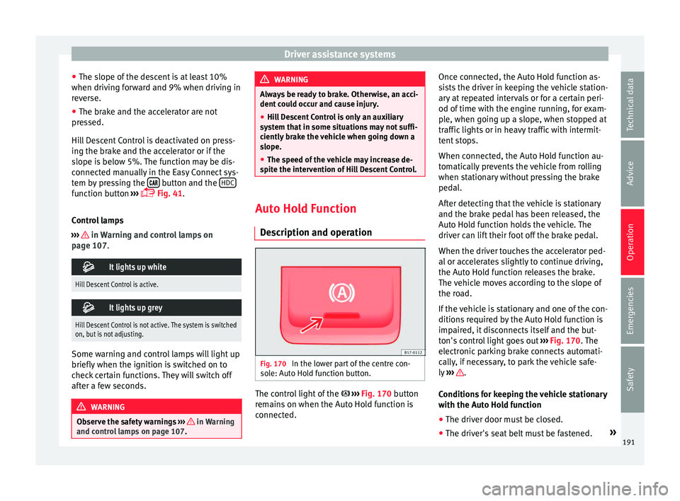
scription and operation Fig. 170
In the lower part of the centre con-
so l
e: Auto Hold function button. The control light of the
› ›
›
Fig. 170 button
remains on when the Auto Hold function is
connected. Once connected, the Auto Hold function as-
si
sts the driver in keeping the vehicle station-
ary at repeated intervals or for a certain peri-
od of time with the engine running, for exam-
ple, when going up a slope, when stopped at
traffic lights or in heavy traffic with intermit-
tent stops.
When connected, the Auto Hold function au-
tomatically prevents the vehicle from rolling
when stationary without pressing the brake
pedal.
After detecting that the vehicle is stationary
and the brake pedal has been released, the
Auto Hold function holds the vehicle. The
driver can lift their foot off the brake pedal.
When the driver touches the accelerator ped-
al or accelerates slightly to continue driving,
the Auto Hold function releases the brake.
The vehicle moves according to the slope of
the road.
If the vehicle is stationary and one of the con-
ditions required by the Auto Hold function is
impaired, it disconnects itself and the but-
ton's control light goes out ››› Fig. 170. The
electronic parking brake connects automati-
cally, if necessary, to park the vehicle safe-
ly ››› .
C ondition
s for keeping the vehicle stationary
with the Auto Hold function
● The driver door must be closed.
● The driver's seat belt must be fastened. »
191
Technical data
Advice
Operation
Emergencies
Safety
Page 201 of 328
Driver assistance systems
Indications on the display, warning
and c ontr
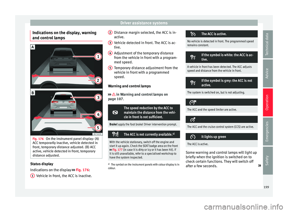
ol lamps Fig. 176
On the instrument panel display: (A)
A C
C temporarily inactive, vehicle detected in
front, temporary distance adjusted. (B) ACC
active, vehicle detected in front, temporary
distance adjusted. Status display
Indic
ation
s on the display ››› Fig. 176:
Vehicle in front, the ACC is inactive.
1 Distance margin selected, the ACC is in-
activ
e.
V
ehicle detected in front. The ACC is ac-
tive.
Adjustment of the temporary distance
from the vehicle in front with a program-
med speed.
Temporary distance adjustment from the
vehicle in front with a programmed
speed.
Warning and control lamps
››› in Warning and control lamps on
p ag
e 107.
The speed reduction by the ACC to
maintain the distance from the vehi-
cle in front is not sufficient.
Brake! apply the foot brake! Driver intervention prompt.
The ACC is not currently available.
a)
With the vehicle stationary, switch off the engine and
start it up again. Check the SEAT badge area on the front
››› Fig. 177 (in case it is dirty or icy or it has been hit). If
it is still unavailable, refer to a specialised workshop to
have the system inspected.
a) The symbol on the instrument panels with colour display is in
colour.
2 3
4
5 The ACC is active.
No vehicle is detected in front. The programmed speed
remains constant.
If the symbol is white: the ACC is ac-
tive.
A vehicle in front has been detected. The ACC adjusts
speed and distance from the vehicle in front.
If the symbol is grey: the ACC is not
active.
The system is switched on, but is not adjusting.
The ACC and the speed limiter are active.
The ACC and the cruise control system (CCS) are active.
It lights up green
The ACC is active.
Some warning and control lamps will light up
briefly
when the ignition i
s switched on to
check certain functions. They will switch off
after a few seconds. »
199
Technical data
Advice
Operation
Emergencies
Safety
Page 227 of 328
Driver assistance systems
Open the Assistants menu.
● BSD
● P arking Assist.
If
the verification box on the control panel is
checked , the functionality will be automat-
ically activated at ignition.
When the blind spot detector is ready to op-
erate, the indications in the external mirrors
will turn on briefly as confirmation.
When the vehicle is restarted, the last adjust-
ment in the system will remain active.
If the blind spot detector was automatically
deactivated, it will only be possible to restart
the system after turning the vehicle off and
restarting it.
Automatic deactivation of the blind spot de-
tector (BSD)
The radar sensors of the blind spot detector
with rear cross traffic alert will be automati-
cally deactivated when, among other rea-
sons, one of the sensors is detected to be
permanently covered. This may be the case if,
for example, there is a layer of snow or ice in
front of one of the sensors.
The relevant text message will appear in the
dash panel display. Trailer mode
The Blind spot
detector and the rear cross
traffic alert will be automatically deactivated
and it will be impossible to activate them if
the tow hitch is electrically connected to a
trailer or other similar object.
As soon as the driver starts to drive with a
trailer connected electrically to the vehicle, a
message will appear on the instrument panel
display indicating that the blind spot detec-
tor and the rear cross traffic alert are deacti-
vated. Once the trailer has been unhitched
from the vehicle, if you want to use the blind
spot detector and the rear cross traffic alert,
you will have to reactivate them in the corre-
sponding menu.
If the towing hitch is not factory equipped,
then the blind spot detector and the rear
cross traffic alert will have to be deactivated
manually when driving with a trailer.
SEAT Drive Profile*
Introduction The SEAT Drive Profile enables the driver to
c
hoo
se between four profiles or modes, Eco,
Normal , Sport and Individual , that
modify the behaviour of various vehicle func-
tions, providing different driving experiences. In addition, the 4Drive version features the
Offroad and Snow profi
les.
The Individual profile can be configured
according to personal preferences. The other
profiles have a fixed configuration.
Description Depending on the equipment fitted in the ve-
hic
l
e, SEAT Drive Profile can operate on the
following functions:
Engine
Depending on the profile selected, the en-
gine responds more spontaneously or more
in harmony with the movements of the accel-
erator. Additionally, when the Eco profile is
selected, the Start-Stop function is automati-
cally activated.
In vehicles with automatic transmission, the
gear change points are modified to position
them in lower or higher engine speed ranges.
Additionally, the Eco profile activates the in-
ertia function, enabling consumption to be
further reduced.
In manual gearbox vehicles, the Eco profile
causes the gear change recommendation in-
dications that appear on the dash panel to
vary, facilitating more efficient driving. »
225
Technical data
Advice
Operation
Emergencies
Safety
Page 258 of 328
Operation
into account the speed limit for vehicles with
tr
ai
lers in the corresponding country, as it
could be less than the speed limit for vehi-
cles without a trailer.
● Never attempt to “straighten” the towing
vehic
le and trailer while accelerating. WARNING
If the towing bracket has been retrofitted by a
non- S
EAT workshop, the Start-Stop system
must be disconnected manually whenever
driving with a trailer. Otherwise the brake
system could be damaged and could conse-
quently cause a serious accident or injury.
● Always disconnect the Start-Stop system
manua
lly when using a towing bracket that
has not been fitted by a SEAT workshop. Note
● Bef
ore hitching or unhitching a trailer, al-
ways deactivate the anti-theft alarm
››› page 112. Otherwise, the tilt sensor could
cause the alarm to go off.
● Do not drive with a trailer for the engine's
firs
t 1000 km ››› page 184.
● SEAT recommends that, if possible, the tow
hitc
h be disassembled or covered when it is
not going to be used. In the event of a rear-
end collision, the damage to the vehicle
could be greater if the bracket is fitted.
● Some retrofitted towing brackets cover the
re
ar towing eye. In these cases, the towing eye should not be used for tow-starting or for
t
o
wing other vehicles. For this reason, if the
vehicle has been retrofitted with a towing
bracket, always keep the tow hitch in the ve-
hicle when you disassemble it. Control lamp
The tow hitch is not securely locked in
position.
Check that the towing bracket is locked
››› page 257. Some warning and control lamps will light up
briefly
when the ignition i
s switched on to
check certain functions. They will switch off
after a few seconds. WARNING
If the warning lamps and the corresponding
me s
sages are ignored when they light up, the
vehicle may stall in traffic and cause acci-
dents and severe injuries.
● Never ignore the warning lamps or messag-
es.
● St
op the vehicle at the next opportunity
and in a saf
e place. CAUTION
Failure to heed the control lamps and corre-
s pondin
g text messages when they light up
may result in damage to the vehicle. Technical requirements
Vehicles that are
fact
ory-equipped with a
towing bracket fulfil all the technical and le-
gal requirements for driving with a trailer.
If the vehicle is retrofitted with a towing
bracket, only a bracket that is authorised for
the maximum authorised load of the trailer
that is to be towed may be fitted. The towing
bracket must be suitable for the vehicle and
the trailer and must be properly secured to
the vehicle's chassis. Only use a towing
bracket that has been authorised by SEAT for
this vehicle. Always check and take into ac-
count the towing bracket manufacturer's in-
structions. Never fit a towing bracket “with
weight distribution” or “load compensation”.
Towing bracket fitted on the bumper
Never fit a towing bracket to the bumper or to
the area where the bumper is mounted. The
towing bracket should not impair the bum-
per's function. Do not make modifications or
repairs to the exhaust system or the brake
system. Make regular checks to ensure that
the towing bracket is secure.
Engine cooling system
Driving with a trailer increases the load on
the engine and cooling system. The cooling
system should have sufficient coolant and be
prepared for the additional effort involved in
driving with a trailer.
256
Page 260 of 328
Operation
Unlock the tow hitch and remove it
● Stop the vehicle and connect the electronic
p ark
ing brake ››› page 170.
● Switch off the engine.
● Open the rear lid.
● Pull the ››› Fig. 217
button briefly. The tow
hitch unlocks electrically and automatically
turns outwards. The control lamp in the but-
ton will flash ››› Fig. 217.
● Remove the tow hitch with your hand until
you f
eel and see that it has engaged and the
control lamp on the button stays on.
● Close the tailgate.
Co
ver the tow hitch
● Stop the vehicle and apply the electronic
park
ing brake.
● Switch off the engine.
● Unhook the trailer and interrupt the electri-
cal
connection between it and the vehicle. If
you are using an adapter, remove it from the
trailer's power socket.
● Open the rear lid.
● Pull the ››
› Fig. 217 button briefly. The tow
hitch unlocks electrically.
● Turn the tow hitch under the bumper with
your h
and until you feel and see that it en-
gages and the control lamp on the ››› Fig. 217
button stays on.
● Close the tailgate. Meaning of control lamp
●
If the warning light of the button ››
› Fig. 217
is flashing , this means that the tow hitch has
not been attached properly or is damaged
››› .
● If the warning lamp st
ays on with the rear
lid open, the tow hitch is correctly in place
both when engaged and when covered.
● The control lamp of the button will go off
appr
ox. 1 minute after closing the rear lid. WARNING
Undue use of the towing bracket may cause
injur y
and accidents.
● Only use the tow hitch if it is properly en-
gag
ed.
● Always ensure that no person, animal or
ob
ject is to be found in the path of the tow
hitch.
● Never use a tool or instrument while the
to
w hitch is moving.
● Never press the ››
› Fig. 217 button when
there is a trailer hooked to the vehicle or
when a carrier system or other accessories
are mounted on the tow hitch.
● If the tow hitch is not attached properly, do
not u
se it. Instead, go to a specialised work-
shop and have the towing bracket checked.
● If you detect any fault in the electrical sys-
tem or in the t
owing bracket, contact a speci-
alised workshop and ask them to check it. ●
If the b
all has a diameter of less than 49
mm at any one point, do not use the towing
bracket under any circumstances. CAUTION
If you clean the vehicle with high-pressure or
s t
eam devices, do not point the jet directly
towards the retractable tow hitch or the trail-
er power socket, as this may damage the
joints or remove the grease necessary for lu-
brication. Note
At extremely low temperatures, the tow hitch
m a
y be impossible to use. In this case, place
the vehicle in a warmer location (for example,
a garage). Fitting a bicycle carrier on the retract-
ab
l
e tow hitch The maximum allowed weight of the carrier
sy
s
tem, including the load, is 75 kg. The car-
rier system should not protrude more than
700 mm backwards from the spherical head.
Only carrier systems on which up to 3 bikes
can be mounted are allowed. Heavier bicy-
cles must be mounted as close to the vehicle
as possible (tow hitch).
258
Page 263 of 328
Towing bracket device*
the anti-theft system, have these checked out
b
y
a specialised workshop.
● If the trailer accessories consume energy
through the po
wer socket to the trailer and
the engine is turned off, the battery will dis-
charge.
● If the vehicle battery is running low, the
electric
al connection with the trailer will be
automatically cut. Loading a trailer
Technically permissible maximum trailer
w
eight
and vertical load on the coupling de-
vice
The technically permissible maximum trailer
weight is the weight that the vehicle can tow
››› . The vertical load on the coupling load
i s
exerted vertically from above on the tow
hitch of the towing bracket ››› page 303.
The information on the maximum trailer
weight and vertical load on the coupling de-
vice contained in the type plate of the towing
bracket are experimental values only. The
correct figures for your specific model, which
may be lower than these figures, are given in
the vehicle documentation. The information
in the vehicle documentation takes prece-
dence at all times.
To promote safety while driving, SEAT recom-
mends making the most of the maximum ver-tical load
technically permissible on the cou-
p
ling device ››› page 255. An insufficient ver-
tical load has a negative influence on the be-
haviour of both the vehicle and trailer.
The vertical load increases the weight on the
rear axle, reducing the vehicle's carrying ca-
pacity.
Gross combination weight of the towing ve-
hicle and trailer
The gross combination weight is the actual
weight of the loaded vehicle plus the actual
weight of the loaded trailer.
In some countries trailers are classified into
distinct categories. SEAT recommends ob-
taining information from a specialised work-
shop regarding which type of trailer is most
suitable for your vehicle.
Trailer loading
The weight of the towing vehicle and trailer
must be balanced. In order to do this, the
load must be as close as possible to the max-
imum vertical load technically permissible on
the coupling point, and it must be evenly dis-
tributed between the back and front of the
trailer:
● Distribute loads in the trailer so that heavy
ob
jects are as near to the axle as possible or
above it.
● Secure the trailer load properly. Tyre pressure
Set the ty
re pressure of the trailer tyres in ac-
cordance with the trailer manufacturer's rec-
ommendations.
When towing a trailer, inflate the tyres of the
towing vehicle with the maximum allowable
pressure ››› page 292. WARNING
If the maximum permissible axle weight, the
m ax
imum load technically permissible on the
coupling point, the maximum authorised ve-
hicle weight or the gross combination weight
of the towing vehicle and trailer are excee-
ded, accidents and serious injuries may oc-
cur.
● Never exceed the values indicated!
● The actual weight on the front and rear
axl
es must never exceed the maximum per-
missible axle weight. The weight on the front
and rear axles must never exceed the maxi-
mum permissible weight. WARNING
A shift in weight could jeopardize the stabili-
ty and sec
urity of the towing vehicle and
trailer, which could lead to accidents and se-
rious injuries.
● Always load the trailer correctly.
● Always secure the load properly using belts
or str
aps that are suitable and in good condi-
tion. 261
Technical data
Advice
Operation
Emergencies
Safety