technical data Seat Ateca 2018 Owner's Manual
[x] Cancel search | Manufacturer: SEAT, Model Year: 2018, Model line: Ateca, Model: Seat Ateca 2018Pages: 348, PDF Size: 7.32 MB
Page 269 of 348
Driver assistance systems
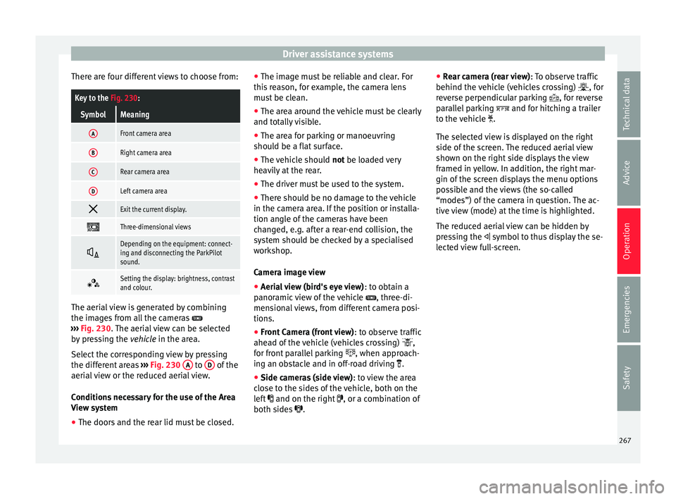
There are four different views to choose from:Key to the Fig. 230:
SymbolMeaning
AFront camera area
BRight camera area
CRear camera area
DLeft camera area
Exit the current display.
Three-dimensional views
Depending on the equipment: connect-
ing and disconnecting the ParkPilot
sound.
Setting the display: brightness, contrast
and colour.
The aerial view is generated by combining
the im
ag
e
s from all the cameras
››› Fig. 230. The aerial view can be selected
by pressing the vehicle in the area.
Select the corresponding view by pressing
the different areas ››› Fig. 230 A to
D of the
aeri al
view or the reduced aerial view.
Conditions necessary for the use of the Area
View system
● The doors and the rear lid must be closed. ●
The image mu
st be reliable and clear. For
this reason, for example, the camera lens
must be clean.
● The area around the vehicle must be clearly
and total
ly visible.
● The area for parking or manoeuvring
should be a fl
at surface.
● The vehicle should not be loaded
very
heavily at the rear.
● The driver must be used to the system.
● There should be no damage to the vehicle
in the camera ar
ea. If the position or installa-
tion angle of the cameras have been
changed, e.g. after a rear-end collision, the
system should be checked by a specialised
workshop.
Camera image view
● Aerial view (bird's eye view) : to obt
ain a
panoramic view of the vehicle , three-di-
mensional views, from different camera posi-
tions.
● Front Camera (front view) : to ob
serve traffic
ahead of the vehicle (vehicles crossing) ,
for front parallel parking , when approach-
ing an obstacle and in off-road driving .
● Side cameras (side view) : to v
iew the area
close to the sides of the vehicle, both on the
left and on the right , or a combination of
both sides . ●
Rear c
amera (rear view) : To observe traffic
behind the vehicle (vehicles crossing) , for
reverse perpendicular parking , for reverse
parallel parking and for hitching a trailer
to the vehicle .
The selected view is displayed on the right
side of the screen. The reduced aerial view
shown on the right side displays the view
framed in yellow. In addition, the right mar-
gin of the screen displays the menu options
possible and the views (the so-called
“modes”) of the camera in question. The ac-
tive view (mode) at the time is highlighted.
The reduced aerial view can be hidden by
pressing the symbol to thus display the se-
lected view full-screen.
267
Technical data
Advice
Operation
Emergencies
Safety
Page 271 of 348
Driver assistance systems
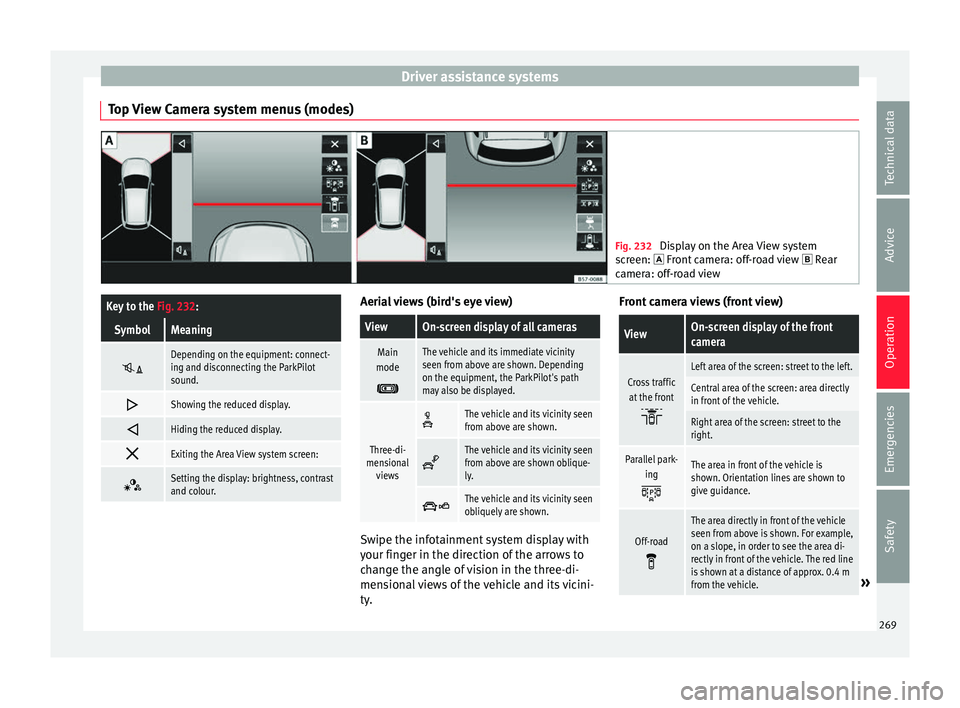
Top View Camera system menus (modes) Fig. 232
Display on the Area View system
sc r
een: Front camera: off-road view Rear
camera: off-road view
Key to the Fig. 232:
SymbolMeaning
Depending on the equipment: connect-
ing and disconnecting the ParkPilot
sound.
Showing the reduced display.
Hiding the reduced display.
Exiting the Area View system screen:
Setting the display: brightness, contrast
and colour. Aerial views (bird's eye view)
ViewOn-screen display of all cameras
Main
mode
The vehicle and its immediate vicinity
seen from above are shown. Depending
on the equipment, the ParkPilot's path
may also be displayed.
Three-di-
mensional views
The vehicle and its vicinity seen
from above are shown.
The vehicle and its vicinity seen
from above are shown oblique-
ly.
The vehicle and its vicinity seen
obliquely are shown.
Swipe the infotainment system display with
y
our fin
g
er in the direction of the arrows to
change the angle of vision in the three-di-
mensional views of the vehicle and its vicini-
ty. Front camera views (front view)
ViewOn-screen display of the front
camera
Cross traffic
at the front
Left area of the screen: street to the left.
Central area of the screen: area directly
in front of the vehicle.
Right area of the screen: street to the
right.
Parallel park- ing
The area in front of the vehicle is
shown. Orientation lines are shown to
give guidance.
Off-road
The area directly in front of the vehicle
seen from above is shown. For example,
on a slope, in order to see the area di-
rectly in front of the vehicle. The red line
is shown at a distance of approx. 0.4 m
from the vehicle.
» 269
Technical data
Advice
Operation
Emergencies
Safety
Page 273 of 348
Driver assistance systems
●
The sys t
em is not a replacement for driver
awareness. Supervise the parking operation
at all times, as well as the vehicle's surround-
ing area. Adapt your speed and driving style
at all times to suit visibility, weather, road
and traffic conditions.
● Do not be distracted from the traffic by
looking at
the screen.
● The images on the rear assist screen are
only tw
o-dimensional. Due to a lack of spatial
depth, protruding parts or holes in the road,
for example, are more difficult to detect or
may not be seen at all.
● Vehicle load modifies the representation of
the orientation lines
displayed. The width
represented by the lines diminishes with ve-
hicle load. Pay special attention to the vehi-
cle's surroundings when the inside of the ve-
hicle of the luggage compartment is carrying
a heavy load.
● In the following situations, the objects or
other vehic
les shown in the navigation sys-
tem display appear to be further away or
closer than they really are: Pay special atten-
tion:
– On moving from a horizontal plane to a
slope.
– On moving from a slope to a horizontal
plane.
– If the vehicle is heavily loaded at the
rear.
– When the vehicle approaches objects
that are not on the ground surface or are
jutting out from it. These objects may al- so be outside the camera's angle of vi-
sion when r
ev
ersing. Note
● It is
important to take great care and pay
special attention if you are not yet familiar
with the system.
● Rear assist will not be available if the vehi-
cle's
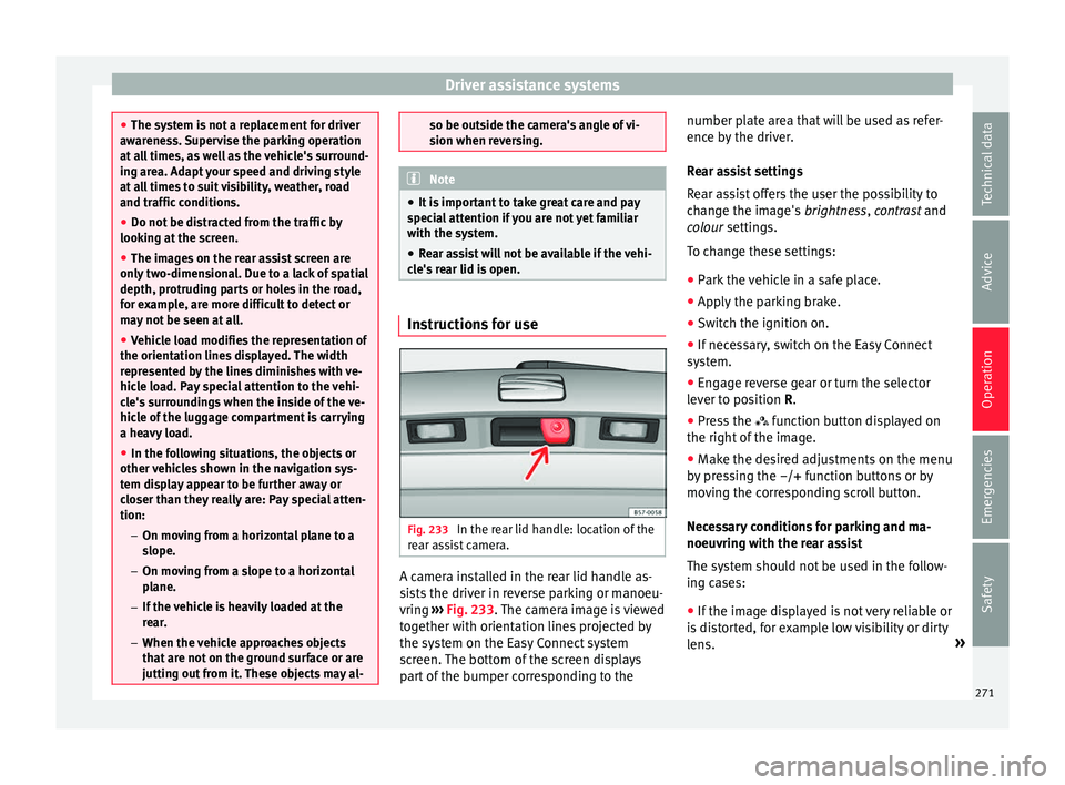
rear lid is open. Instructions for use
Fig. 233
In the rear lid handle: location of the
r e
ar a
ssist camera. A camera installed in the rear lid handle as-
s
i
s
ts the driver in reverse parking or manoeu-
vring ››› Fig. 233. The camera image is viewed
together with orientation lines projected by
the system on the Easy Connect system
screen. The bottom of the screen displays
part of the bumper corresponding to the number plate area that will be used as refer-
ence by
the driver.
Rear assist settings
Rear assist offers the user the possibility to
change the image's brightness, contrast and
colour settings.
To change these settings:
● Park the vehicle in a safe place.
● Apply the parking brake.
● Switch the ignition on.
● If necessary, switch on the Easy Connect
syst
em.
● Engage reverse gear or turn the selector
lever t
o position R.
● Press the function b
utton displayed on
the right of the image.
● Make the desired adjustments on the menu
by pr
essing the –/+ function buttons or by
moving the corresponding scroll button.
Necessary conditions for parking and ma-
noeuvring with the rear assist
The system should not be used in the follow-
ing cases:
● If the image displayed is not very reliable or
is di
storted, for example low visibility or dirty
lens. »
271
Technical data
Advice
Operation
Emergencies
Safety
Page 275 of 348
Towing bracket device*
● OR: Pr e
s
s the RVC function button 1)
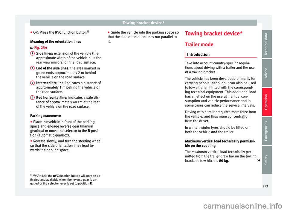
Meaning of the orientation lines
››› Fig. 234
Side lines: extension of the vehicle (the
approximate width of the vehicle plus the
rear view mirrors) on the road surface.
End of the side lines: the area marked in
green ends approximately 2 m behind
the vehicle on the road surface.
Intermediate line: indicates a distance of
approximately 1 m behind the vehicle on
the road surface.
Red horizontal line: indicates a safe dis-
tance of approximately 40 cm at the rear
of the vehicle on the road surface.
Parking manoeuvre ● Place the vehicle in front of the parking
spac
e and engage reverse gear (manual
gearbox) or move the selector to the R posi-
tion (automatic gearbox).
● Reverse slowly, and turn the steering wheel
so that the s
ide orientation lines lead to-
wards the parking space. 1 2
3
4 ●
Guide the v
ehic
le into the parking space so
that the side orientation lines run parallel to
it. Towing bracket device*
T r
ai
ler mode
Introduction Take into account country-specific regula-
tions
about
driving with a trailer and the use
of a towing bracket.
The vehicle has been developed primarily for
carrying people, although it can also be used
to tow a trailer if fitted with the correspond-
ing technical equipment. This additional load
has an effect on the useful life, fuel con-
sumption and vehicle performance and in
some cases can reduce the service intervals.
Driving with a trailer requires more force from
the vehicle, and thus more concentration
from the driver.
In winter, winter tyres should be fitted on
both the vehicle and the trailer.
Maximum vertical load technically permissi-
ble on the coupling
The maximum vertical load technically per-
mitted from the trailer draw bar on the towing
bracket's tow hitch is 80 kg. »1)
WARNING: the RVC function b
utton will only be ac-
tivated and available when the reverse gear is en-
gaged or the selector lever is set to position R.
273
Technical data
Advice
Operation
Emergencies
Safety
Page 277 of 348

Towing bracket device*
not going to be used. In the event of a rear-
end co
l
lision, the damage to the vehicle
could be greater if the bracket is fitted.
● Some retrofitted towing brackets cover the
rear t
owing eye. In these cases, the towing
eye should not be used for tow-starting or for
towing other vehicles. For this reason, if the
vehicle has been retrofitted with a towing
bracket, always keep the tow hitch in the ve-
hicle when you disassemble it. Control lamp
Lamp on button lights up
The tow hitch is not securely locked in position.
Check that the towing bracket is locked
››› page 276. Some warning and control lamps will light up
briefly
when the ignition i
s
switched on to
check certain functions. They will switch off
after a few seconds. WARNING
If the warning lamps and the corresponding
mes s
ages are ignored when they light up, the
vehicle may stall in traffic and cause acci-
dents and severe injuries.
● Never ignore the warning lamps or messag-
es.
● Stop the
vehicle at the next opportunity
and in a safe p
lace. CAUTION
Failure to heed the control lamps and corre-
spondin g t
ext messages when they light up
may result in damage to the vehicle. Technical requirements
Vehicles that are
factor
y-equipped with a
towing bracket fulfil all the technical and le-
gal requirements for driving with a trailer.
If the vehicle is retrofitted with a towing
bracket, only a bracket that is authorised for
the maximum authorised load of the trailer
that is to be towed may be fitted. The towing
bracket must be suitable for the vehicle and
the trailer and must be properly secured to
the vehicle's chassis. Only use a towing
bracket that has been authorised by SEAT for
this vehicle. Always check and take into ac-
count the towing bracket manufacturer's in-
structions. Never fit a towing bracket “with
weight distribution” or “load compensation”.
Towing bracket fitted on the bumper
Never fit a towing bracket to the bumper or to
the area where the bumper is mounted. The
towing bracket should not impair the bum-
per's function. Do not make modifications or
repairs to the exhaust system or the brake
system. Make regular checks to ensure that
the towing bracket is secure. Engine cooling system
Drivin
g w
ith a trailer increases the load on
the engine and cooling system. The cooling
system should have sufficient coolant and be
prepared for the additional effort involved in
driving with a trailer.
Trailer brakes
If the trailer has its own brake system, please
take the relevant legal requirements into ac-
count. Never connect the trailer's brake sys-
tem to the vehicle's brake system.
Tow rope
Always use a cable between the vehicle and
the trailer ››› page 278.
Trailer rear lights
The trailer's rear lights should comply with
the statutory safety regulations ››› page 278.
Never connect the trailer's rear lights directly
to the vehicle's electric system. If you are not
sure that the trailer's electrical connection is
correct, have it checked by a specialised
workshop. SEAT recommends visiting a SEAT
dealership for this.
Exterior mirrors
If you cannot see the area behind the trailer
with the exterior mirrors of the towing vehi-
cle, additional mirrors will have to be instal-
led in accordance with the regulations of the »
275
Technical data
Advice
Operation
Emergencies
Safety
Page 279 of 348
Towing bracket device*
● Turn the t
o
w hitch under the bumper with
your hand until you feel and see that it en-
gages and the control lamp on the ››› Fig. 235
button stays on.
● Close the rear lid.
Meanin
g of control lamp
● If the warning light of the button ›››
Fig. 235
is flashing , this means that the tow hitch has
not been attached properly or is damaged
››› .
● If the warning lamp st
a
ys on with the rear
lid open, the tow hitch is correctly in place
both when engaged and when covered.
● The control lamp of the button will go off
appro
x. 1 minute after closing the rear lid. WARNING
Undue use of the towing bracket may cause
injury and ac
cidents.
● Only use the tow hitch if it is properly en-
gaged.
● A
lways ensure that no person, animal or
obj
ect is to be found in the path of the tow
hitch.
● Never use a tool or instrument while the
tow hit
ch is moving.
● Never press the ›››
Fig. 235 button when
there is a trailer hooked to the vehicle or
when a carrier system or other accessories
are mounted on the tow hitch. ●
If the t o
w hitch is not attached properly, do
not use it. Instead, go to a specialised work-
shop and have the towing bracket checked.
● If you detect any fault in the electrical sys-
tem or in the to
wing bracket, contact a speci-
alised workshop and ask them to check it.
● If the ball has a diameter of less than 49
mm at any
one point, do not use the towing
bracket under any circumstances. CAUTION
If you clean the vehicle with high-pressure or
s te
am devices, do not point the jet directly
towards the retractable tow hitch or the trail-
er power socket, as this may damage the
joints or remove the grease necessary for lu-
brication. Note
At extremely low temperatures, the tow hitch
ma y
be impossible to use. In this case, place
the vehicle in a warmer location (for example,
a garage). Fitting a bicycle carrier on the retract-
ab
le t
ow hitch The maximum allowed weight of the carrier
sy
s
t
em, including the load, is 75 kg. The car-
rier system should not protrude more than
700 mm backwards from the spherical head.
Only carrier systems on which up to 3 bikes can be mounted are allowed. Heavier bicy-
cle
s must be mounted as close to the vehicle
as possible (tow hitch). WARNING
The incorrect use of the tow hitch with a bicy-
cl e r
ack mounted on the tow hitch can cause
accidents and injury.
● Never exceed the maximum weight or the
limits indic
ated above.
● The bicycle rack may not be mounted to the
neck of
the hitch below the ball because, due
to the shape of the neck and depending on
the rack model, the rack could be incorrectly
mounted on the vehicle.
● Always read and take the manufacturer as-
sembly in
structions into account. CAUTION
If the maximum weight and limits indicated
abov e ar
e exceeded, the vehicle may suffer
considerable damage.
● Never exceed the values indicated! Note
SEAT recommends removing, as far as possi-
bl e, a
ll removable parts of the bicycles before
setting off. These parts include, for example,
baskets and saddlebags, child seats or bat-
teries. This improves aerodynamics and the
centre of gravity of the rack system. 277
Technical data
Advice
Operation
Emergencies
Safety
Page 281 of 348
Towing bracket device*
Before hitching or unhitching a trailer, always
t urn off
the anti-thef
t alarm. Otherwise, the
tilt sensor could cause the alarm to go off.
Trailers with LED rear lights
For technical reasons, trailers fitted with LED
rear lights cannot be connected to the anti-
theft alarm system.
When the vehicle is locked, the alarm does
not go off when the electrical connection with
the trailer is cut if it has rear lights with light-
emitting diodes.
If the Eco driving profile was selected when
hitching the trailer, this will automatically
switch to the Normal profile. If the system
cannot detect the attached trailer or if the
towing bracket has been retrofitted by an au-
to repair shop other than SEAT, you must
manually select the Normal profile before you
start driving with a trailer attached. To recon-
nect the Eco profile once the trailer has been
unhitched, switch the ignition off and back
on once. WARNING
If the cables are improperly or incorrectly
connect ed, it
may lead to an excessive
amount of current supplied to the trailer,
which can cause abnormalities in the entire
vehicle electronic system, as well as acci-
dents and serious injuries. ●
Ens ur
e that any repairs that need to be car-
ried out on the electrical system are carried
out by a specialised workshop.
● Never connect the trailer's electric system
directly t
o the electrical connections of the
tail lights or any other power sources. WARNING
Contact between the pins of the trailer power
soc ket
can cause short circuits, overloading
of the electrical system or failure of the light-
ing system, and consequently can cause acci-
dents and serious injuries.
● Never connect the pins of the trailer power
socket
to each other.
● Make sure any work on bent pins is carried
out by
a specialised workshop. CAUTION
Do not leave the trailer connected to the vehi-
cl e when p
arked; place it on its support
wheel or its supports. If the vehicle rises or
falls due, for example, to a variation of the
load or a burst tyre, increased pressure will
be placed on the towing bracket and the trail-
er, and both the vehicle and the trailer can be
damaged. Note
● In ca se of
malfunctioning of the electrical
systems of the vehicle or trailer, as well as of the anti-theft system, have these checked out
by
a s
pecialised workshop.
● If the trailer accessories consume energy
through the pow
er socket to the trailer and
the engine is turned off, the battery will dis-
charge.
● If the vehicle battery is running low, the
electrica
l connection with the trailer will be
automatically cut. Loading a trailer
Technically permissible maximum trailer
w
eight
and
vertical load on the coupling de-
vice
The technically permissible maximum trailer
weight is the weight that the vehicle can tow
››› . The vertical load on the coupling load
i s
e
xerted vertically from above on the tow
hitch of the towing bracket ››› page 319.
The information on the maximum trailer
weight and vertical load on the coupling de-
vice contained in the type plate of the towing
bracket are experimental values only. The
correct figures for your specific model, which
may be lower than these figures, are given in
the vehicle documentation. The information
in the vehicle documentation takes prece-
dence at all times. »
279
Technical data
Advice
Operation
Emergencies
Safety
Page 283 of 348
Towing bracket device*
● The tr ai
l
er weight, as well as the gross com-
bination weight of the towing vehicle and
trailer, change the centre of gravity and the
properties of the vehicle.
● If the towing vehicle is empty and the trail-
er is lo
aded, then the load distribution is in-
correct. Under these conditions, drive slowly
and with extra caution.
Hill starts with a trailer
Depending on the slope of the hill and the
combination weight of the towing vehicle
and trailer, the vehicle might start rolling
backwards slightly when you first start up.
For hill-starting with a trailer, do the follow-
ing:
● Press and hold the brake pedal.
● Press the button t
o disconnect the elec-
tronic parking brake ››› page 186.
● If the vehicle is equipped with a manual
gearbo
x, push the clutch pedal all the way
down.
● Put the vehicle into first gear or turn the se-
lector l
ever to position D/S ››› page 192.
● Pull out the button and ho
ld it in that
position to stop the towing vehicle and trailer
with the electronic parking brake.
● Release the brake pedal.
● Start driving slowly. To do this, in the case
of a manual
gearbox, slowly release the
clutch pedal. ●
Do not rel
ease the button until the en-
gine has sufficient force to start driving. WARNING
If a trailer is pulled incorrectly, this may lead
to lo s
s of control of the vehicle and serious
injury.
● Driving with a trailer and transporting
heavy or l
arge objects will change the vehicle
handling and braking distances.
● Always drive cautiously and carefully.
Brake e
arlier than usual.
● Adapt your speed and driving style at all
times t
o suit visibility, weather, road and traf-
fic conditions. Slow down, especially when
driving down hills or slopes.
● Accelerate with particular care and caution.
Avoid s
udden braking and manoeuvres.
● Take great care when overtaking. Reduce
speed immediat
ely if you notice that the trail-
er is swaying, however slightly.
● Never attempt to “straighten” the towing
vehicl
e and trailer while accelerating.
● Take into account the speed limit for vehi-
cle
s with a trailer, as it could be lower than
for vehicles without a trailer. Stabilisation of the towing vehicle
and tr
ai
l
er The stabilisation of the towing vehicle and
trai
l
er together is an additional function of
the electronic stability control (ESC).
If the system detects that the trailer is sway-
ing, it intervenes automatically with the driv-
er steering recommendation to reduce the
swaying of the trailer.
Requirements for the stabilisation of the
towing vehicle and trailer
● The vehicle is factory-equipped with a tow-
ing br ac
ket or has been retro-fitted with a
compatible towing bracket.
● The ESC and ASR are active. The control
lamp or is
not lit up on the instrument
panel.
● The trailer is electrically connected to the
tow
ing vehicle through the trailer power
socket.
● The vehicle is travelling at over 60 km/h
(appro
x. 37 mph).
● The maximum vertical load technically per-
miss
ible is being utilised on the coupling de-
vice.
● The trailer has a rigid draw bar.
● If the trailer has brakes, it must be equip-
ped with a mech
anical overrun brake. »
281
Technical data
Advice
Operation
Emergencies
Safety
Page 285 of 348
Towing bracket device*
or any other unsuitable power sources. Only
use s
uit
able connectors to connect the trail-
er.
● The towing bracket should be retrofitted
only at
a specialised workshop. WARNING
If the towing bracket is badly fitted or unsuit-
ab le, the tr
ailer may separate from the vehi-
cle while driving. This could cause serious ac-
cidents and fatal injuries. Note
Only use towing brackets that have been ap-
pro v
ed by SEAT for the model in question. 283
Technical data
Advice
Operation
Emergencies
Safety
Page 286 of 348
Advice
Advice
C ar
e and m
aintenance
Accessories and modifications to the vehicle
Accessories, replacement parts and
repair work Always ask your dealer or specialist retailer
f
or a
dv
ice before purchasing accessories and
replacement parts.
Your vehicle is designed to offer a high
standard of active and passive safety. For this
reason, we recommend that you ask a SEAT
Official Service for advice before fitting ac-
cessories or replacement parts. Your SEAT Of-
ficial Service has the latest information from
the manufacturer and can recommend acces-
sories and replacement parts which are suita-
ble for your requirements. They can also an-
swer any questions you might have regarding
official regulations.
We recommend you to use only SEAT acces-
sories and Genuine SEAT parts ®
. SEAT has
tested these parts and accessories for suita-
bility, reliability and safety. SEAT Official
Services have the necessary experience and
facilities to ensure that the parts are installed
correctly and professionally. Any
retro-fitted equipment which has a direct
effect
on the vehicle and/or the way it is driv-
en, such as a cruise control system or elec-
tronically-controlled suspension, must be
approved for use in your vehicle and bear the
e mark (the European Union's authorisation
symbol).
If any additional electrical devices are fitted
which do not serve to control the vehicle it-
self (for instance a refrigerator box, laptop or
ventilator fan, etc.), they must bear the
sign (manufacturer conformity declaration in
the European Union). WARNING
Accessories, for example telephone holders
or cup ho l
ders, should never be fitted on the
covers, or within the working range of the air-
bags. Otherwise, there is a danger of injury if
the airbag is triggered in an accident. Technical modifications
Modifications must always be carried out ac-
c
or
din
g to our specifications.
Unauthorised modifications to the electronic
components, software, wiring or data transfer
in the vehicle may cause malfunctioning. Due
to the way the electronic components are
linked together in networks, other indirect
systems may be affected by the faults. This
can seriously impair safety, lead to excessive wear of components, and also invalidate your
vehicl
e registration documents.
You will appreciate that your SEAT dealership
cannot be held liable for any damage caused
by modifications and/or work performed in-
correctly.
We therefore recommend that all work should
be performed by a SEAT Official Service using
genuine SEAT parts ®
. WARNING
Incorrectly performed modifications or other
work on
your vehicle can lead to malfunctions
and cause accidents. Radio transmitters and office equip-
ment
Radio transmitters (fixed installation)
An
y
r
etrofit installations of radio transmitters
in the vehicle require prior approval. SEAT
generally authorises in-vehicle installations
of approved types of radio transmitters provi-
ded that:
● The aerial is installed correctly.
● The aerial is installed on the exterior of the
vehicl
e (and shielded cables are used togeth-
er with non-reflective aerial trimming).
● The effective transmitting power does not
exc
eed 10 Watts at the aerial base.
284