ignition Seat Ateca 2018 User Guide
[x] Cancel search | Manufacturer: SEAT, Model Year: 2018, Model line: Ateca, Model: Seat Ateca 2018Pages: 348, PDF Size: 7.32 MB
Page 42 of 348
The essentialsMenuFunction
Detection of
traffic
signsDisplay of traffic signs ŌĆ║ŌĆ║ŌĆ║ page 245:
Fatigue de-
tection *Switching the fatigue detection on
or off (pause recommendation)
ŌĆ║ŌĆ║ŌĆ║ page 248. Status display
Bonnet, r e
ar lid and door
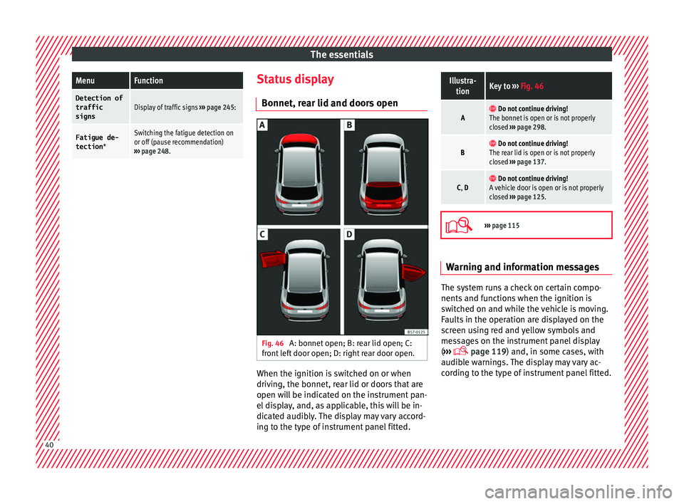
s open Fig. 46
A: bonnet open; B: rear lid open; C:
fr ont
l
eft door open; D: right rear door open. When the ignition is switched on or when
driv
in
g, the bonnet, r
ear lid or doors that are
open will be indicated on the instrument pan-
el display, and, as applicable, this will be in-
dicated audibly. The display may vary accord-
ing to the type of instrument panel fitted.
Illustra- tionKey to ŌĆ║ŌĆ║ŌĆ║ Fig. 46
A ’é▓ Do not continue driving!
The bonnet is open or is not properly
closed ŌĆ║ŌĆ║ŌĆ║ page 298.
B ’é▓ Do not continue driving!
The rear lid is open or is not properly
closed ŌĆ║ŌĆ║ŌĆ║ page 137.
C, D ’é▓ Do not continue driving!
A vehicle door is open or is not properly
closed ŌĆ║ŌĆ║ŌĆ║ page 125. ’Ć®
ŌĆ║ŌĆ║ŌĆ║
page 115 Warning and information messages
The system runs a check on certain compo-
nents
and f
u
nctions when the ignition is
switched on and while the vehicle is moving.
Faults in the operation are displayed on the
screen using red and yellow symbols and
messages on the instrument panel display
( ŌĆ║ŌĆ║ŌĆ║
’Ć® page 119) and, in some cases, with
audible warnings. The display may vary ac-
cording to the type of instrument panel fitted. 40
Page 44 of 348
The essentials
When the vehicle is at a standstill or when
tr av
el
ling at very low speeds, the tempera-
ture displayed may be higher than the true
outside temperature as a result of the heat
produced by the engine.
The temperatures measured range from
-40┬░C to +50┬░C (-40┬░F to +122┬░F).
Engine oil temperature display Vehicles without multifunction steering
wheel
ŌŚÅ Press the rocker switch ŌĆ║
ŌĆ║ŌĆ║
Fig. 43 2 until
the m ain menu ap
pe
ars. Enter into Driving
data . With the button 2 move to the oil
t emper
at
ure gauge.
Vehicles with multifunction steering wheel
ŌŚÅ Enter the submenu Driving data and
turn the thumbwheel
until the oil tempera-
ture display appears.
The engine reaches its operating temperature
when in normal driving conditions, the oil
temperature is between 80┬░C (180┬░F) and
120┬░C (250┬░F) . If the engine is required to
work hard and the outside temperature is
high, the engine oil temperature can in-
crease. This does not present any problem as
long as the warning lamps ’üź ŌĆ║ŌĆ║ŌĆ║
table on
page 47 or ’éż ŌĆ║ŌĆ║ŌĆ║ table on page 47 do not
appear on the display. Additional consumers ŌŚÅ
Operation with the windscreen wiper lever*:
Pre s
s the rocker switch ŌĆ║ŌĆ║ŌĆ║ Fig. 43 2 until the
main menu ap pe
ars. Enter into the section
Driving data . With the rocker switch,
move to the display Convenience con-
sumers .
ŌŚÅ Operation with the multi-function steering
wheel*:
move with the buttons ’āī
’é© or
’é© ’āŹ to Driving data
and enter with
OK. Turn
the right thumbwheel until the Conven-
ience consumers display appears.
In addition, a scale will inform you of the cur-
rent sum of all the additional appliances.
Saving tips Tips on how to save fuel will be displayed in
c
ondition
s
that increase fuel consumption.
Follow them to reduce consumption. The indi-
cations appear automatically only with the ef-
ficiency programme. After a time, the tips will
disappear automatically.
If you wish to hide a saving tip immediately
after it appears, press any button on the
windscreen wiper lever*/multifunction steer-
ing wheel*. Note
ŌŚÅ If y
ou hide a saving tip, it will reappear af-
ter you switch the ignition on again.
ŌŚÅ The saving tips do not appear in all situa-
tions, but
rather with a large separation of
time. Speed warning device
The speed warning device warns the driver
when they h
av
e exceeded the pre-set speed
limit by 3 km/h (2 mph). An audible warning
signal sounds, and the warning lamp ’é® and
the driver message Speed limit excee-
ded! will be displayed simultaneously on the
instrument panel. The warning lamp ’é®
switches off when reducing speed below the
stored maximum limit.
Speed warning programming is recommen-
ded if you wish to be reminded of a maxi-
mum speed, such as when travelling in a
country with different speed limits or for a
maximum speed for winter tyres.
Setting speed limit warning
You can use the radio or the Easy Connect* to
set, alter or cancel the speed limit warning.
ŌŚÅ Vehicles with radio : pres
s the SETUP button
> c ontr
o
l button ’āŻ Driver Assistant >
Speed warning .42
Page 45 of 348
The essentials
ŌŚÅ Vehicle
s
with Easy Connect : Press the ’üā’üü’üÆbutton and the function button SETTINGS >
Driver assistance > ACC > Dis-
tance .
The w arnin
g limit
can be set from 30 to
240 km/h (20 to 149 mph). The adjustment
is made at 10 km/h (5 mph) intervals. Note
ŌŚÅ Ple a
se bear in mind that, even with the
speed warning function, it is still important
to keep an eye on the vehicle speed with the
speedometer and to observe the legal speed
limits.
ŌŚÅ The speed limit warning function in the ver-
sion for some c
ountries warns you at a speed
of 120 km/h (75 mph). This is a factory-set
speed limit. Service intervals
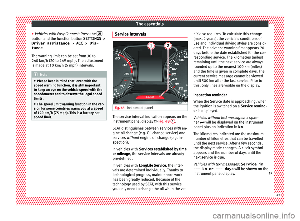
Fig. 48
Instrument panel The service interval indication appears on the
in
s
trument
panel display ŌĆ║ŌĆ║ŌĆ║ Fig. 48 1 .
S EA
T di
stinguishes between services with en-
gine oil change (e.g. Oil change service) and
services without engine oil change (e.g. In-
spection).
In vehicles with Services established by time
or mileage, the service intervals are already
pre-defined.
In vehicles with LongLife Service , the inter-
vals are determined individually. Thanks to
technological progress, maintenance work
has been greatly reduced. Because of the
technology used by SEAT, with this service
you only need to change the oil when the ve- hicle so requires. To calculate this change
(max. 2 y
ears), the vehicle's conditions of
use and individual driving styles are consid-
ered. The advance warning first appears 20
days before the date established for the cor-
responding service. The kilometres (miles)
remaining until the next service are always
rounded up to the nearest 100 km (miles)
and the time is given in complete days. The
current service message cannot be viewed
until 500 km after the last service. Prior to
this, only lines are visible on the display.
Inspection reminder
When the Service date is approaching, when
the ignition is switched on a Service remind-
er is displayed.
Vehicles without text messages : a span-
ner ’üż will be displayed on the instrument
panel plus an indication in km.
The kilometres indicated are the maximum
number of kilometres that can be travelled
until the next service. After a few seconds,
the display mode changes. A clock symbol
appears and the number of days until the
next service is due.
Vehicles with text messages : Service in
--- km or --- days will be shown on the
instrument panel display. ┬╗ 43
Page 46 of 348
The essentials
Service due
When the ser v
ic
e date is due, an audible
warning is given when the ignition is switch-
ed on and the spanner displayed on the
screen flashes for a few seconds ’üż.
Vehicles with text messages : Service now
will be shown on the instrument panel dis-
play.
Reading a service notification
With the ignition switched on, the engine off
and the vehicle at a standstill, the current
service notification can be read:
Press and hold the button 0.0/SET for more
th an 5 sec
ond
s to consult the service mes-
sage 2 .
When the ser v
ic
e date has passed , a minus
sign is displayed in front of the number of kil-
ometres or days.
Vehicles with text messages : the following
message is displayed: Service --- km
(miles) or --- days ago .
Resetting service interval display
If the service was not carried out by a SEAT
dealership, the display can be reset as fol-
lows: ŌŚÅ Switch off the ignition, press and hold the
button 0.0/S
ET
2 .
ŌŚÅ Switch ignition back on. ŌŚÅ
Rel
e
ase the button 0.0/SET and press it
ag ain f
or the ne
xt 20 seconds. Note
ŌŚÅ The serv ic
e message disappears after a few
seconds, when the engine is started or when OK/RESET is pressed on the windscreen wiper
lev er
, or OK on the multifunction steering
wheel.
ŌŚÅ In v
ehicles with the LongLife system in
which the batt
ery has been disconnected for
a long period of time, it is not possible to cal-
culate the date of the next service. Therefore
the service interval display may not be cor- rect. In this case, bear in mind the maximum
service intervals permitted in the ŌĆ║ŌĆ║ŌĆ║ Booklet
Maintenance Programme.
ŌŚÅ If you reset the display manually, the next
servic
e interval will be indicated as in vehi-
cles with fixed service intervals. For this rea-
son we recommend that the service interval
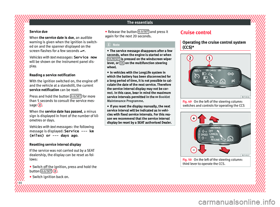
display be reset by a SEAT authorised Dealer. Cruise control
Oper atin
g the c
ruise control system
(CCS)* Fig. 49
On the left of the steering column:
sw it
c
hes and controls for operating the CCS Fig. 50
On the left of the steering column:
thir d l
ev
er to operate the CCS. 44
Page 50 of 348
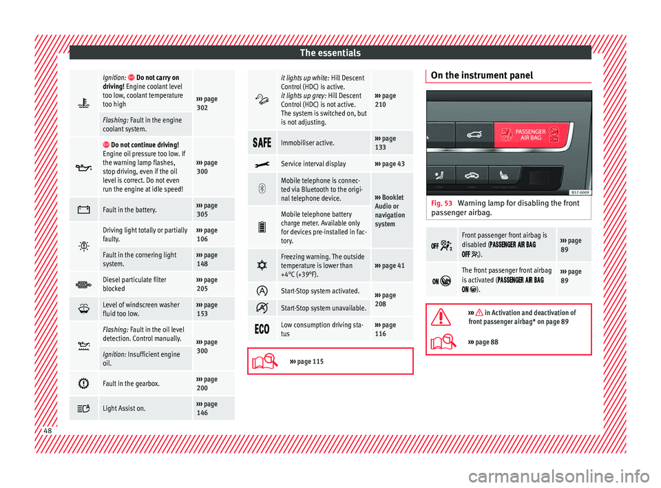
The essentials
’é┐Ignition: ’é▓ Do not carry on
driving! Engine coolant level
too low, coolant temperature
too high
ŌĆ║ŌĆ║ŌĆ║ page
302
Flashing: Fault in the engine
coolant system. ’üź ’é▓
Do not continue driving!
Engine oil pressure too low. If
the warning lamp flashes,
stop driving, even if the oil
level is correct. Do not even
run the engine at idle speed!
ŌĆ║ŌĆ║ŌĆ║ page
300 ’ü”
Fault in the battery.ŌĆ║ŌĆ║ŌĆ║
page
305 ’ĆĮ
Driving light totally or partially
faulty.ŌĆ║ŌĆ║ŌĆ║
page
106
Fault in the cornering light
system.ŌĆ║ŌĆ║ŌĆ║ page
148 ’āĘ
Diesel particulate filter
blockedŌĆ║ŌĆ║ŌĆ║
page
205 ’ü╣
Level of windscreen washer
fluid too low.ŌĆ║ŌĆ║ŌĆ║
page
153 ’Ʀ
Flashing: Fault in the oil level
detection. Control manually.
ŌĆ║ŌĆ║ŌĆ║
page
300
Ignition: Insufficient engine
oil. ’āü
Fault in the gearbox.ŌĆ║ŌĆ║ŌĆ║
page
200 ’üć
Light Assist on.ŌĆ║ŌĆ║ŌĆ║
page
146 ’üæ
it lights up white:
Hill Descent
Control (HDC) is active.
it lights up grey: Hill Descent
Control (HDC) is not active.
The system is switched on, but
is not adjusting.
ŌĆ║ŌĆ║ŌĆ║ page
210 ’üō’üü’üå’üģ
Immobiliser active.ŌĆ║ŌĆ║ŌĆ║
page
133 ’üż
Service interval displayŌĆ║ŌĆ║ŌĆ║
page 43 ’Ƭ
Mobile telephone is connec-
ted via Bluetooth to the origi-
nal telephone device.
ŌĆ║ŌĆ║ŌĆ║
Booklet
Audio or
navigation
system ’üģ
Mobile telephone battery
charge meter. Available only
for devices pre-installed in fac-
tory.
’üø
Freezing warning. The outside
temperature is lower than
+4┬░C (+39┬░F).ŌĆ║ŌĆ║ŌĆ║
page 41 ’ā”
Start-Stop system activated.ŌĆ║ŌĆ║ŌĆ║
page
208 ’é¦
Start-Stop system unavailable.
’üģ’üā’üÅ
Low consumption driving sta-
tusŌĆ║ŌĆ║ŌĆ║
page
116 ’Ć®
ŌĆ║ŌĆ║ŌĆ║
page 115 On the instrument panel
Fig. 53
Warning lamp for disabling the front
p a
s
senger airbag. ’üÅ’üå’üå
’Ć╣
Front passenger front airbag is
disabled (’üÉ’üü’üō’üō’üģ’üÄ’üć’üģ’üÆ ’üü’üē’üÆ ’üé’üü’üć
’üÅ’üå’üå ’Ć╣).
ŌĆ║ŌĆ║ŌĆ║ page
89 ’üÅ’üÄ
’éČ
The front passenger front airbag
is activated (’üÉ’üü’üō’üō’üģ’üÄ’üć’üģ’üÆ ’üü’üē’üÆ ’üé’üü’üć
’üÅ’üÄ ’éČ).
ŌĆ║ŌĆ║ŌĆ║ page
89 ’Ƭ
ŌĆ║ŌĆ║ŌĆ║ in Activation and deactivation of
front passenger airbag* on page 89
’Ć®ŌĆ║ŌĆ║ŌĆ║ page 88 48
Page 64 of 348
The essentials
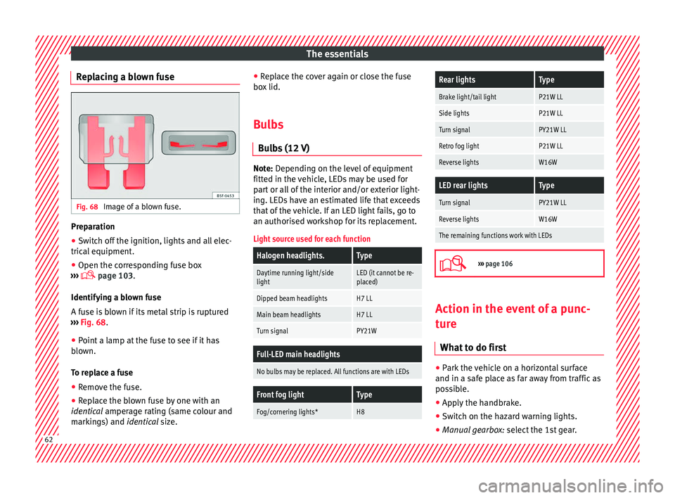
Replacing a blown fuse Fig. 68
Image of a blown fuse. Preparation
ŌŚÅ
Switch off the ignition, lights and all elec-
tric al
equipment
.
ŌŚÅ Open the corresponding fuse box
ŌĆ║ŌĆ║ŌĆ║
’Ć® page 103.
Identifying a blown fuse
A fuse is blown if its metal strip is ruptured
ŌĆ║ŌĆ║ŌĆ║ Fig. 68.
ŌŚÅ Point a lamp at the fuse to see if it has
blown.
T
o replace a fuse
ŌŚÅ Remove the fuse.
ŌŚÅ Replace the blown fuse by one with an
identica
l amperage rating (same colour and
markings) and identical size. ŌŚÅ
Repl
ace the cover again or close the fuse
box lid.
Bulbs Bul
bs (12 V) Note: Depending on the level of equipment
fitt
ed in the
vehicle, LEDs may be used for
part or all of the interior and/or exterior light-
ing. LEDs have an estimated life that exceeds
that of the vehicle. If an LED light fails, go to
an authorised workshop for its replacement.
Light source used for each function
Halogen headlights.Type
Daytime running light/side
lightLED (it cannot be re-
placed)
Dipped beam headlightsH7 LL
Main beam headlightsH7 LL
Turn signalPY21W
Full-LED main headlights
No bulbs may be replaced. All functions are with LEDs
Front fog lightType
Fog/cornering lights*H8
Rear lightsType
Brake light/tail lightP21W LL
Side lightsP21W LL
Turn signalPY21W LL
Retro fog lightP21W LL
Reverse lightsW16W
LED rear lightsType
Turn signalPY21W LL
Reverse lightsW16W
The remaining functions work with LEDs ’Ć®
ŌĆ║ŌĆ║ŌĆ║
page 106 Action in the event of a punc-
t
ur
e
Wh
at to do first ŌŚÅ
Park the vehicle on a horizontal surface
and in a s af
e p
lace as far away from traffic as
possible.
ŌŚÅ Apply the handbrake.
ŌŚÅ Switch on the hazard warning lights.
ŌŚÅ Manual gearbox: select the 1s
t gear.62
Page 70 of 348
The essentials
Emergency towing of the vehi-
c l
e
T
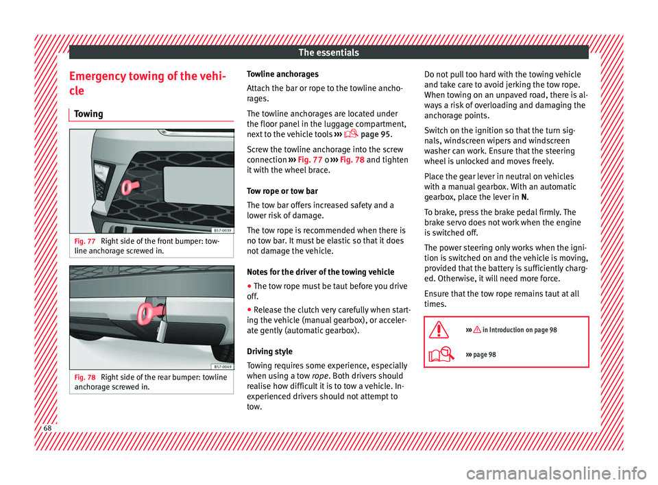
owing Fig. 77
Right side of the front bumper: tow-
line anc hor
ag
e screwed in. Fig. 78
Right side of the rear bumper: towline
anc hor
ag
e screwed in. Towline anchorages
Att
ac
h the b
ar or rope to the towline ancho-
rages.
The towline anchorages are located under
the floor panel in the luggage compartment,
next to the vehicle tools ŌĆ║ŌĆ║ŌĆ║
’Ć® page 95.
Screw the towline anchorage into the screw
connection ŌĆ║ŌĆ║ŌĆ║ Fig. 77 o ŌĆ║ŌĆ║ŌĆ║ Fig. 78 and tighten
it with the wheel brace.
Tow rope or tow bar
The tow bar offers increased safety and a
lower risk of damage.
The tow rope is recommended when there is
no tow bar. It must be elastic so that it does
not damage the vehicle.
Notes for the driver of the towing vehicle
ŌŚÅ The tow rope must be taut before you drive
off.
ŌŚÅ Rel
ease the clutch very carefully when start-
ing the v
ehicle (manual gearbox), or acceler-
ate gently (automatic gearbox).
Driving style
Towing requires some experience, especially
when using a tow rope. Both drivers should
realise how difficult it is to tow a vehicle. In-
experienced drivers should not attempt to
tow. Do not pull too hard with the towing vehicle
and take c
are to avoid jerking the tow rope.
When towing on an unpaved road, there is al-
ways a risk of overloading and damaging the
anchorage points.
Switch on the ignition so that the turn sig-
nals, windscreen wipers and windscreen
washer can work. Ensure that the steering
wheel is unlocked and moves freely.
Place the gear lever in neutral on vehicles
with a manual gearbox. With an automatic
gearbox, place the lever in N.
To brake, press the brake pedal firmly. The
brake servo does not work when the engine
is switched off.
The power steering only works when the igni-
tion is switched on and the vehicle is moving,
provided that the battery is sufficiently charg-
ed. Otherwise, it will need more force.
Ensure that the tow rope remains taut at all
times.
’Ƭ
ŌĆ║ŌĆ║ŌĆ║ in Introduction on page 98
’Ć®ŌĆ║ŌĆ║ŌĆ║ page 98 68
Page 71 of 348
The essentials
Tow-starting If the engine will not start, first try starting it
us
in
g the battery of another vehicle
ŌĆ║ŌĆ║ŌĆ║ page 69. You should only attempt to tow-
start a vehicle if charging the battery does
not work. This is done by leveraging wheel
movement.
When tow-starting a vehicle with a petrol en-
gine, do not tow it more than a short dis-
tance, otherwise unburned fuel can enter the
catalytic converter.
ŌŚÅ Engage 2nd or 3rd gear before moving off.
ŌŚÅ Press the clutch and hold the pedal down.
ŌŚÅ Switch the ignition on.
ŌŚÅ Once both vehicles are moving, release the
clut c
h.
ŌŚÅ As soon as the engine has started, press
the clutc
h and move the gear lever to neutral.
How to jump start Jump lea
dsThe jump lead must have a sufficient wire
c
r
o
ss section.
If the engine fails to start because of a dis-
charged battery, the battery can be connec-
ted to the battery of another vehicle to start
the engine. Jump leads must comply with standard
DIN
72553 (see cabl
e manufacturer's instruc-
tions). The wire cross section must be at least
25 mm 2
for petrol engines and at least
35 mm 2
for diesel engines. Note
ŌŚÅ The v ehic
les must not touch each other,
otherwise electricity could flow as soon as
the positive terminals are connected.
ŌŚÅ The discharged battery must be properly
connected t
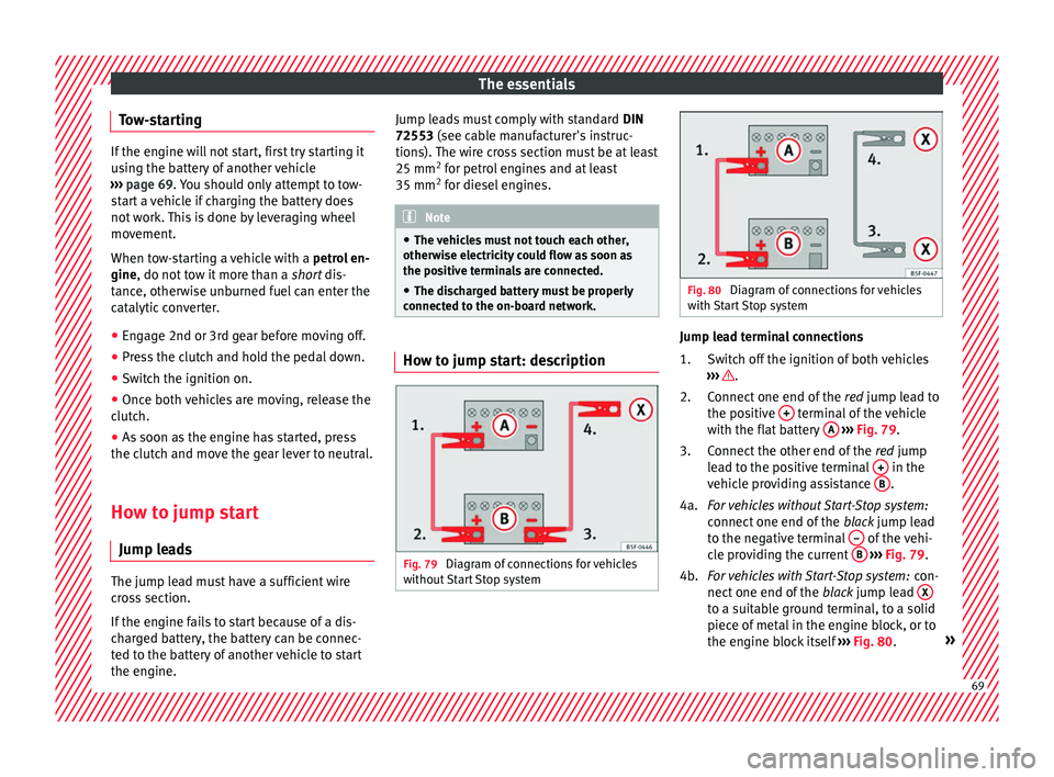
o the on-board network. How to jump start: description
Fig. 79
Diagram of connections for vehicles
w ithout
Start Stop system Fig. 80
Diagram of connections for vehicles
with St
art Stop system Jump lead terminal connections
Swit
c
h off the ignition of both vehicles
ŌĆ║ŌĆ║ŌĆ║ .
C onnect
one end of
the red jump lead to
the positive + terminal of the vehicle
w ith the fl
at
battery A
ŌĆ║ ŌĆ║
ŌĆ║ Fig. 79 .
Connect the other end of the red jump
lead to the positive terminal + in the
v ehic
l
e providing assistance B .
F or
vehicles without Start-Stop system:
connect one end of the black jump lead
to the negative terminal ŌĆō of the vehi-
c l
e pr
oviding the current B
ŌĆ║ ŌĆ║
ŌĆ║ Fig. 79 .
For vehicles with Start-Stop system: con-
nect one end of the black jump lead X to a suitable ground terminal, to a solid
piec
e of
met
al in the engine block, or to
the engine block itself ŌĆ║ŌĆ║ŌĆ║ Fig. 80. ┬╗
1.
2.
3.
4a.
4b.
69
Page 73 of 348
The essentials
Changing the wiper blades W ind
s
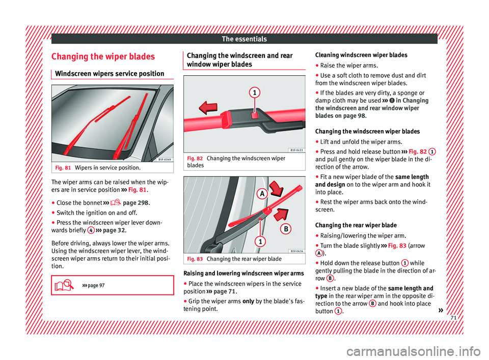
creen wipers service position Fig. 81
Wipers in service position. The wiper arms can be raised when the wip-
er
s
ar
e in service position ŌĆ║ŌĆ║ŌĆ║ Fig. 81.
ŌŚÅ Close the bonnet ŌĆ║ŌĆ║ŌĆ║
’Ć® page 298.
ŌŚÅ Switch the ignition on and off.
ŌŚÅ Press the windscreen wiper lever down-
ward
s briefly 4
ŌĆ║ ŌĆ║
ŌĆ║ page 32.
Before driving, always lower the wiper arms.
Using the windscreen wiper lever, the wind-
screen wiper arms return to their initial posi-
tion.
’Ć®
ŌĆ║ŌĆ║ŌĆ║ page 97 Changing the windscreen and rear
w
indo
w w
iper blades Fig. 82
Changing the windscreen wiper
b l
a
des Fig. 83
Changing the rear wiper blade Raising and lowering windscreen wiper arms
ŌŚÅ Place the windscreen wipers in the service
po s
ition ŌĆ║
ŌĆ║ŌĆ║ page 71.
ŌŚÅ Grip the wiper arms only b
y the blade's fas-
tening point. Cleaning windscreen wiper blades
ŌŚÅ
Raise the wiper arms.
ŌŚÅ Use a soft cloth to remove dust and dirt
from the wind
screen wiper blades.
ŌŚÅ If the blades are very dirty, a sponge or
damp cloth m
ay be used ŌĆ║ŌĆ║ŌĆ║ in Changing
the w ind
s
creen and rear window wiper
blades on page 98.
Changing the windscreen wiper blades
ŌŚÅ Lift and unfold the wiper arms.
ŌŚÅ Press and hold release button ŌĆ║ŌĆ║ŌĆ║
Fig. 82 1 and pull gently on the wiper blade in the di-
r
ection of
the arr
ow.
ŌŚÅ Fit a new wiper blade of the same len
gth
and design on to the wiper arm and hook it
into place.
ŌŚÅ Rest the wiper arms back onto the wind-
scr
een.
Changing the rear wiper blade
ŌŚÅ Raising/lowering the wiper arm.
ŌŚÅ Turn the blade slightly ŌĆ║ŌĆ║ŌĆ║
Fig. 83 (arrow
A ).
ŌŚÅ Hold down the release button 1 while
g ently
p
ulling the blade in the direction of ar-
row B .
ŌŚÅ Insert a new blade of the same l
en
gth and
type in the rear wiper arm in the opposite di-
rection to the arrow B and hook into place
b utt
on 1 .
┬╗ 71
Page 81 of 348
Seat belts
Seat belts
Wh y
w
ear a seat belt
Number of seats Your vehicle has
five se
ats, two in the front
and three in the rear. Each seat is equipped
with a three-point seat belt.
In some versions, your vehicle is approved
only for four seats. Two front seats and two
rear seats. WARNING
ŌŚÅ Never tr an
sport more than the permitted
amount of people in your vehicle.
ŌŚÅ Every vehicle occupant must properly fas-
ten and we
ar the seat belt belonging to his or
her seat. Children must be protected with an
appropriate child restraint system. Seat belt control lamp* ’üÜ
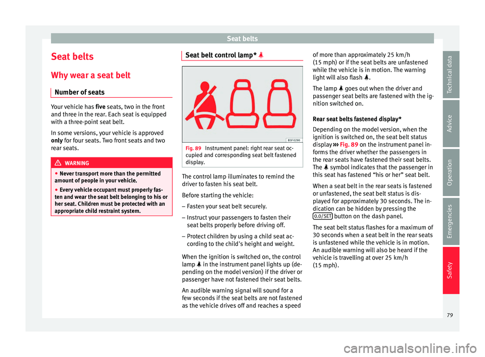
Fig. 89
Instrument panel: right rear seat oc-
c upied and c
orr
esponding seat belt fastened
display. The control lamp illuminates to remind the
driv
er t
o f
asten his seat belt.
Before starting the vehicle: ŌĆō Fasten your seat belt securely.
ŌĆō Instruct your passengers to fasten their
seat belts
properly before driving off.
ŌĆō Protect children by using a child seat ac-
cordin
g to the child's height and weight.
When the ignition is switched on, the control
lamp ’üÜ in the instrument panel lights up (de-
pending on the model version) if the driver or
passenger have not fastened their seat belts.
An audible warning signal will sound for a
few seconds if the seat belts are not fastened
as the vehicle drives off and reaches a speed of more than approximately 25 km/h
(15 mph) or if the seat
belts are unfastened
while the vehicle is in motion. The warning
light will also flash ’üÜ.
The lamp ’üÜ goes out when the driver and
passenger seat belts are fastened with the ig-
nition switched on.
Rear seat belts fastened display*
Depending on the model version, when the
ignition is switched on, the seat belt status
display ŌĆ║ŌĆ║ŌĆ║ Fig. 89 on the instrument panel in-
forms the driver whether the passengers in
the rear seats have fastened their seat belts.
The ’üÜ symbol indicates that the passenger in
this seat has fastened ŌĆ£his or herŌĆØ seat belt.
When a seat belt in the rear seats is fastened
or unfastened, the seat belt status is dis-
played for approximately 30 seconds. The in-
dication can be hidden by pressing the 0.0/SET button on the dash panel.
The se at
belt
status flashes for a maximum of
30 seconds when a seat belt in the rear seats
is unfastened while the vehicle is in motion.
An audible warning will also be heard if the
vehicle is travelling at over 25 km/h
(15 mph).
79
Technical data
Advice
Operation
Emergencies
Safety