technical data Seat Ateca 2018 User Guide
[x] Cancel search | Manufacturer: SEAT, Model Year: 2018, Model line: Ateca, Model: Seat Ateca 2018Pages: 348, PDF Size: 7.32 MB
Page 91 of 348
Airbag system
WARNING
● The driver of the
vehicle is responsible for
disabling or switching on the airbag.
● Always switch off the ignition before disa-
bling the fr
ont passenger airbag! Failure to do
so could result in a fault in the airbag deacti-
vation system.
● Never leave the key in the airbag disabling
switc
h as it could get damaged or enable or
disable the airbag during driving.
● If for any reason an airbag is deactivated,
reactiv
ate it as soon as possible so that it can
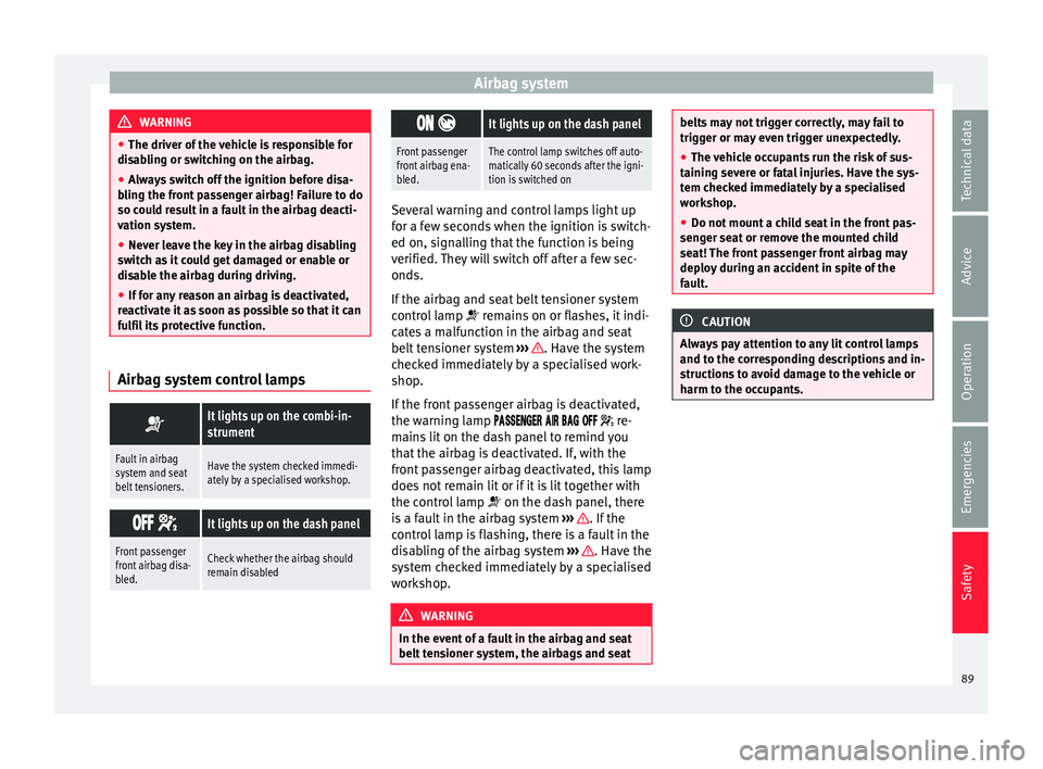
fulfil its protective function. Airbag system control lamps
It lights up on the combi-in-
strument
Fault in airbag
system and seat
belt tensioners.Have the system checked immedi-
ately by a specialised workshop.
It lights up on the dash panel
Front passenger
front airbag disa-
bled.Check whether the airbag should
remain disabled
It lights up on the dash panel
Front passenger
front airbag ena-
bled.The control lamp switches off auto-
matically 60 seconds after the igni-
tion is switched on
Several warning and control lamps light up
for a f
ew sec
onds when the ignition is switch-
ed on, signalling that the function is being
verified. They will switch off after a few sec-
onds.
If the airbag and seat belt tensioner system
control lamp remains on or flashes, it indi-
cates a malfunction in the airbag and seat
belt tensioner system ››› . Have the system
c hec
k
ed immediately by a specialised work-
shop.
If the front passenger airbag is deactivated,
the warning lamp re-
mains lit on the dash panel to remind you
that the airbag is deactivated. If, with the
front passenger airbag deactivated, this lamp
does not remain lit or if it is lit together with
the control lamp on the dash panel, there
is a fault in the airbag system ››› . If the
c ontr
o
l lamp is flashing, there is a fault in the
disabling of the airbag system ››› . Have the
sy s
t
em checked immediately by a specialised
workshop. WARNING
In the event of a fault in the airbag and seat
belt t en
sioner system, the airbags and seat belts may not trigger correctly, may fail to
trigg
er or m
ay even trigger unexpectedly.
● The vehicle occupants run the risk of sus-
taining sev
ere or fatal injuries. Have the sys-
tem checked immediately by a specialised
workshop.
● Do not mount a child seat in the front pas-
senger se
at or remove the mounted child
seat! The front passenger front airbag may
deploy during an accident in spite of the
fault. CAUTION
Always pay attention to any lit control lamps
and to the c orr
esponding descriptions and in-
structions to avoid damage to the vehicle or
harm to the occupants. 89
Technical data
Advice
Operation
Emergencies
Safety
Page 93 of 348
Transporting children safely
WARNING
● If a c hi
ld seat is secured to the front pas-
senger seat, the risk to the child of sustain-
ing critical or fatal injuries in the event of an
accident increases.
● An inflating front passenger airbag can
strike the r
ear-facing child seat and project it
with great force against the door, the roof or
the backrest.
● Never install a child seat facing backwards
on the front p
assenger seat unless the front
passenger front airbag has been disabled.
Risk of potentially fatal injuries to the child!
However, if it is necessary, in exceptional ca-
ses, to transport a child in the front passen-
ger seat, the front passenger front airbag
must always be disabled ››› page 89. If the
passenger seat has a height adjustment op-
tion, move it to the highest, most upright po-
sition. If you have a fixed seat, do not install
any child restraint system in this location.
● For those vehicles that do not include a key
lock sw
itch to deactivate the airbag, the vehi-
cle must be taken to a technical service. Do
not forget to reconnect the airbag when an
adult wants to sit in the front passenger seat.
● All vehicle occupants, especially children,
must
assume the proper sitting position and
be properly belted in while travelling.
● Never hold children or babies on your lap,
this c
an result in potentially fatal injuries to
the child!
● Never allow a child to be transported in a
vehicl
e without being properly secured, or to stand up or kneel on a seat while travelling.
In an acc
ident, the c
hild could be flung
through the vehicle, causing possibly fatal in-
juries to themselves and to the other vehicle
occupants.
● If children assume an improper sitting posi-
tion when the vehic
le is moving, they expose
themselves to greater risk of injury in the
event of a sudden braking manoeuvre or in an
accident. This is particularly important if the
child is travelling on the front passenger seat
and the airbag system is triggered in an acci-
dent; as this could cause serious injury or
even death.
● A suitable child seat can protect your child!
● Never leave a child alone in the child seat
or inside the
vehicle because depending on
the season, very high temperatures may be
reached inside a parked vehicle, which could
be fatal.
● Children who are less than 1.5 metres tall
must
not wear a normal seat belt without a
child seat, as this could cause injuries to the
abdominal and neck areas during a sudden
braking manoeuvre or in an accident.
● Do not allow the seat belt to become twis-
ted and the seat
belt should be properly in
place ››› page 79.
● Only one child may occupy a child seat
›››
page 91, Child seats.
● When a child seat is mounted in the rear
seats, the door c
hild-proof lock should be ac-
tivated ››› page 134. Child seats
Saf ety
in
structions Read the additional information carefully
›› ›
page 24. WARNING
When travelling, children must be secured in
the v ehic
le with a restraint system suitable
for age, weight and size.
● Read and always observe information and
warning
s concerning the use of child seats
››› page 90. WARNING
The retaining rings are designed only for use
with “ISOFIX” and T op
Tether* system child
seats.
● Never secure other child seats that do not
have the “ISOFIX” or T
op Tether* system, or
retaining belts or objects to the fastening
rings - this can result in potentially fatal inju-
ries to the child.
● Ensure that the child seat is secured cor-
rectly u
sing the “ISOFIX” and Top Tether* se-
curing rings. WARNING
An undue installation of the safety seat will
incr e
ase the risk of injury in the event of a
crash. » 91
Technical data
Advice
Operation
Emergencies
Safety
Page 95 of 348
Transporting children safely
The child seat has two rigid attachment clips,
c al
l
ed connectors. These connectors are fit-
ted into the ISOFIX attachment rings found
between the seat cushion and the backrest of
the vehicle's back seat (on the sides). ISOFIX
attachment systems are used mainly in Eu-
rope ›››
page 26. If necessary, ISOFIX at-
tachment may have to be supplemented with
a Top Tether belt or a support bracket.
● Automatic three-point seat belt . Whenever
po
ssible, it is preferable to attach the child
seats with the ISOFIX system rather than at-
taching them with an automatic three-point
seat belt ›››
page 25.
Additional attachment:
● Top Tether : The Top Tether belt is guided
ov
er the back of the rear seat and attached to
an anchor point with a hook. Anchor points
are located at the back of the rear seat back-
rest on the boot side ›››
page 29
. The
rings for retaining the Top Tether belt are
marked with an anchor symbol.
● Support bracket : Some chi
ld seats rest on
the floor of the vehicle with a support brack-
et. The support bracket prevents the child
seat from tipping forward in the event of im-
pact. Child seats fitted with a support bracket
should only be used in the passenger seat
and side rear seats ››› . For the assembly of
thi s
type of
seat you should also consult the
list of approved vehicles for this assembly, available in the instructions for child restraint
syst
ems.
Recommended systems for attaching child
seats
SEAT recommends attaching child seats as
follows:
● Baby carriers or child seats in the opposite
direction of tr
avel: ISOFIX and support brack-
et or iSize.
● Child seats in the direction of travel: ISO-
FIX and T
op Tether. WARNING
Incorrect use of the support bracket can
cau se seriou
s or fatal injury.
● Make sure the support bracket is correctly
and safely
installed. 93
Technical data
Advice
Operation
Emergencies
Safety
Page 97 of 348

Self-help
Emergencies
Self -help
V ehic
le tool kit, anti-puncture kit* The tools and anti-puncture kit* are stored
under the floor p
anel
in the luggage compart-
ment.
To access the vehicle tools:
– Lift up the floor surface by the plastic han-
dle u nti
l it is fastened to the tabs on both
sides.
Depending on the vehicle equipment, the an-
ti-puncture kit* is located under the floor
panel in the luggage compartment.
The tool kit includes:
● Jack*
● Wire hook for pulling off the wheel cov-
er*/wheel bolt
cap clip.
● Box spanner for wheel bolts*
● Towline anchorage
● Adapter for the anti-theft wheel bolts*
● Towing bracket device
Some of the items
listed are only provided in
certain model versions, or are optional ex-
tras. Note
The jack does not generally require any main-
ten anc
e. If required, it should be greased us-
ing universal type grease. Tyre repair
TMS (T
yre Mobility System)* Read the additional information carefully
›› ›
page 63
The Anti-puncture kit* (Tyre Mobility System)
will reliably seal punctures caused by the
penetration of a foreign body of up to about
4 mm in diameter. Do not remove foreign ob-
jects, e.g. screws or nails, from the tyre.
After inserting the sealant residue in the tyre,
you must again check the tyre pressure about
10 minutes after starting the engine.
You should only use the tyre mobility set if
the vehicle is parked in a safe place, you are
familiar with the procedure and you have the
necessary tyre mobility set! Otherwise, you
should seek professional assistance.
Do not use the tyre sealant in the following
cases:
● If the wheel rim has been damaged.
● In outside temperatures below -20°C (-4°F). ●
In the ev ent
of
cuts or perforations in the
tyre greater than 4 mm.
● If you have been driving with very low pres-
sure or a c
ompletely flat tyre.
● If the sealant bottle has passed its use by
date. WARNING
Using the tyre mobility system can be dan-
ger ou
s, especially when filling the tyre at the
roadside. Please observe the following rules
to minimise the risk of injury:
● Stop the vehicle safely as soon as possible.
Park it
at a safe distance from surrounding
traffic to fill the tyre.
● Ensure the ground on which you park is flat
and solid.
● Al
l passengers and particularly children
must
keep a safe distance from the work area.
● Turn on the hazard warning lights to warn
other roa
d users.
● Use the tyre mobility system only if you are
famili
ar with the necessary procedures. Oth-
erwise, you should seek professional assis-
tance.
● The tyre mobility set is intended for tempo-
rary
emergency use only until you can reach
the nearest specialised workshop.
● Replace the repaired tyre with the tyre mo-
bility
set as soon as possible. » 95
Technical data
Advice
Operation
Emergencies
Safety
Page 99 of 348
Self-help
CAUTION
Switch off the air compressor after a maxi-
mum of 8 oper ation
al minutes to avoid over-
heating! Before switching on the air compres-
sor again, let it cool for several minutes. Check after 10 minutes of driving
Screw the inflator tube
›››
Fig. 97 5 again
and chec k
the pressure on the gauge 6 .
1.3 bar (19 p s
i / 130 kPa) and lower:
● Stop the vehicle! The tyre c
annot be sealed
sufficiently with the tyre mobility set.
● You should obtain professional assistance
›››
.
1.4 b ar (20 p
s
i / 140 kPa) and higher:
● Set the tyre pressure to the correct value
again.
● Car
efully resume your journey until you
reac
h the nearest specialised workshop with-
out exceeding 80 km/h (50 mph).
● Have the damaged tyre replaced. WARNING
Driving with an unsealed tyre is dangerous
and can c au
se accidents and serious injury.
● Do not continue driving if the tyre pressure
is 1.3
bar (19 psi / 130 kPa) and lower. ●
Seek s pec
ialist assistance. Manual unlocking/locking
Introduction Read the additional information carefully
›› ›
page 16,
›››
page 17.
The doors, rear lid and panoramic tilting sun-
roof can be locked manually and partially
opened, for example if the key or the central
locking is damaged. WARNING
Opening and closing doors carelessly can
cau se seriou
s injury.
● If the vehicle is locked from outside, the
doors and w
indows cannot be opened from
the inside.
● Never leave children or disabled people
alone in the car
. They could be trapped in the
car in an emergency and will not be able to
get themselves to safety.
● Depending on the time of the year, temper-
ature
s inside a locked and closed vehicle can
be extremely high or extremely low resulting
in serious injuries and illness or even death,
particularly for young children. WARNING
Getting in the way of the doors and the rear
lid is d
angerous and can lead to serious in-
jury.
● Open and close the doors and the rear lid
only when ther
e is nobody in the way. CAUTION
When opening and closing in an emergency,
car ef
ully disassemble components and then
reassemble them carefully to avoid damage
to the vehicle. Changing the windscreen wiper
b
la
des
Changing the windscreen and rear
window wiper blades Read the additional information carefully
› ›
›
page 71.
The windscreen wiper blades are supplied as
standard with a layer of graphite. This layer is
responsible for ensuring that the wipe is si-
lent. If the graphite layer is damaged, the
noise of the water as it is wiped across the
windscreen will be louder.
Check the condition of the wiper blades regu-
larly. If the wipers scrape across the glass ,»
97
Technical data
Advice
Operation
Emergencies
Safety
Page 101 of 348
Self-help
–
Ac c
elerate with particular care and cau-
tion.
– Avoid sudden braking and manoeuvres.
– Brake earlier than usual and more
smoothly. CAUTION
● To av oid d
amaging the vehicle, for example
the paint, remove and replace the lid and
towing eye carefully.
● Unburnt fuel could enter the catalytic con-
vert
er and damage it during towing. Indications for tow-starting
Vehicle's should not generally be tow-star-
t
ed.
The jump s
tart should be used instead
››› page 69.
For technical reasons, towing the following
vehicles is not allowed:
● Vehicles with an automatic gearbox.
● If the vehicle battery is discharged, be-
cause in
vehicles with the Keyless Access
locking and ignition system the steering re-
mains locked and the electronic parking
brake cannot be deactivated nor can the elec-
tronic lock of the steering column be re-
leased if they are activated. ●
If the batt
ery is flat, it is possible that the
engine control units may not operate correct-
ly.
However, if the vehicle must absolutely be
tow-started (in the case of manual gearbox-
es):
● Engage the 2nd or 3rd gear.
● Keep the clutch pressed down.
● Switch on the ignition and the hazard warn-
ing lights.
● Once both
vehicles are moving, release the
clutc
h.
● Once the engine starts, press the clutch
and diseng
age the gear to avoid colliding
with the towing vehicle. CAUTION
When tow-starting, unburnt fuel could enter
the cat a
lytic converter and damage it. Note
The vehicle can only be tow-started if the
electr onic
parking brake and, if appropriate,
the electronic lock of the steering column are
deactivated. If the vehicle has no power sup-
ply or there is an electric system fault, the
engine must be tow-started to deactivate the
electronic parking brake and the electronic
lock of the steering column. Indications for towing
Tow rope or tow bar
It i
s
safer for the vehicle to be towed using a
tow bar, avoiding damage to the vehicle. A
tow rope should only be used if a tow bar is
not available.
A tow rope should be slightly elastic to avoid
damage to both vehicles. It is advisable to
use a tow rope made of synthetic fibre or sim-
ilarly elastic material.
Only attach the tow rope or the tow bar to the
towing eyes provided or a towing bracket.
If the vehicle is factory-equipped with a tow-
ing bracket, it is only allowed to tow with a
tow bar if this has been specially designed to
be installed with a tow hitch ›››
page 276.
When the vehicle needs to be towed:
Check whether the vehicle may be towed
››› page 100, Cases where towing a vehicle
is not allowed .
● Switch the ignition on.
● Put the gearbox lever in neutral or the se-
lect or l
ever in the N ›››
page 192 position.
● Do not allow the vehicle to be towed at
speeds
of over 50 km/h (30 mph).
● The vehicle must not be towed further than
50 km (30 mil e
s). »
99
Technical data
Advice
Operation
Emergencies
Safety
Page 103 of 348
Self-help
● Sc r
ew the t
owing eye in the housing by
turning it to the maximum anticlock-
wise ››› . Use a suitable object that can
c omp
l
etely and securely tighten the towing
eye in its housing.
● After towing, unscrew the towing eye clock
-
wise with a suitable object.
● Insert the side tab of the lid into the open-
ing of the b
umper and press until the tab is
properly clipped into the bumper.
● Clean the towing eye if necessary and then
stor
e it in the luggage compartment along
with the other vehicle tools. CAUTION
The towing eye must always be completely
and firmly tight
ened. Otherwise, it could be
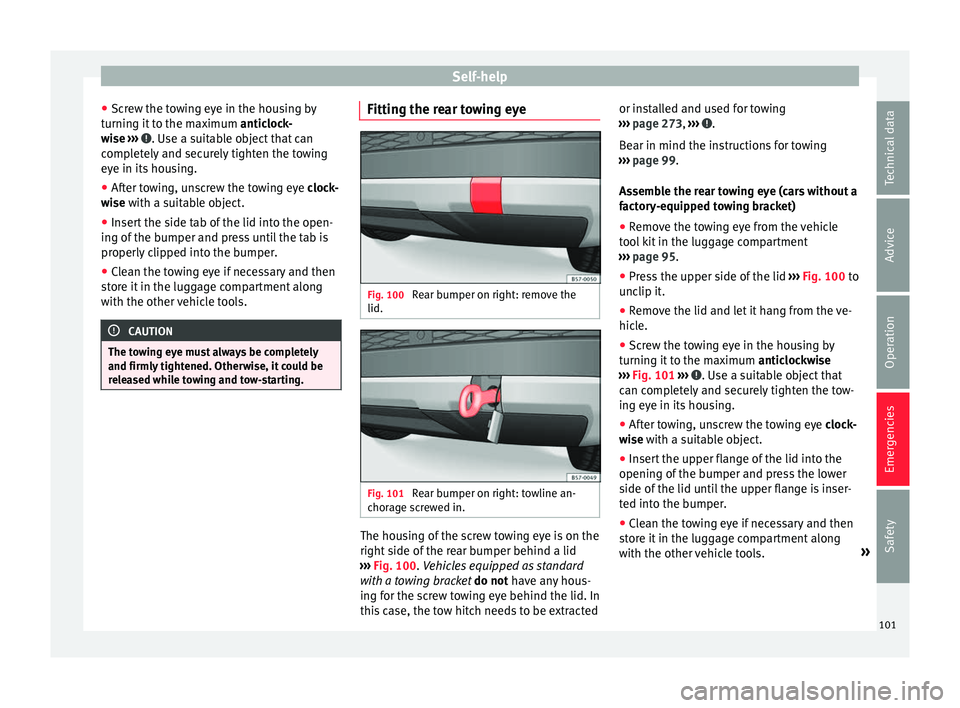
released while towing and tow-starting. Fitting the rear towing eye
Fig. 100
Rear bumper on right: remove the
lid. Fig. 101
Rear bumper on right: towline an-
c hor ag
e screwed in. The housing of the screw towing eye is on the
right
s
ide of
the rear bumper behind a lid
››› Fig. 100. Vehicles equipped as standard
with a towing bracket do not have any hous-
ing for the screw towing eye behind the lid. In
this case, the tow hitch needs to be extracted or installed and used for towing
›››
page 273, ››› .
B e
ar in mind the in
structions for towing
››› page 99.
Assemble the rear towing eye (cars without a
factory-equipped towing bracket)
● Remove the towing eye from the vehicle
tool
kit in the luggage compartment
››› page 95.
● Press the upper side of the lid ›››
Fig. 100 to
unclip it.
● Remove the lid and let it hang from the ve-
hicle.
● Sc
rew the towing eye in the housing by
turning it
to the maximum anticlockwise
››› Fig. 101 ››› . Use a suitable object that
c an c
omp
letely and securely tighten the tow-
ing eye in its housing.
● After towing, unscrew the towing eye clock
-
wise with a suitable object.
● Insert the upper flange of the lid into the
opening of the b
umper and press the lower
side of the lid until the upper flange is inser-
ted into the bumper.
● Clean the towing eye if necessary and then
stor
e it in the luggage compartment along
with the other vehicle tools. »
101
Technical data
Advice
Operation
Emergencies
Safety
Page 105 of 348
Fuses and bulbs
●
Never u se a f
use with a higher value. Only
replace fuses with a fuse of the same amper-
age (same colour and markings) and size.
● Never repair a fuse.
● Never replace a fuse by a metal strip, staple
or simil
ar. CAUTION
● To pr ev
ent damage to the vehicle's electric
system, before replacing a fuse always turn
off the ignition, the lights and all electrical
elements and remove the key from the igni-
tion.
● If you replace a fuse with higher-rating
fuse,
you could cause damage to another part
of the electrical system.
● Protect the fuse boxes when open to pre-
vent the entr
y of dust or humidity as they can
damage the electrical system. Note
● One component m
ay have more than one
fuse.
● Several components may run on a single
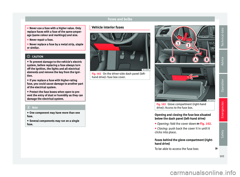
fuse. Vehicle interior fuses
Fig. 102
On the driver-side dash panel (left-
h and driv
e): f
use box cover. Fig. 103
Glove compartment (right-hand
driv e): A
c
cess to the fuse box. Opening and closing the fuse box situated
belo
w the d
a
sh panel (left-hand drive)
● Opening: fold the cover down ››
› Fig. 102.
● Closing: push back the cover it in until it
clic
ks into place.
Fuses behind the glove compartment (right-
hand drive)
To be able to access the fuse box: »
103
Technical data
Advice
Operation
Emergencies
Safety
Page 107 of 348
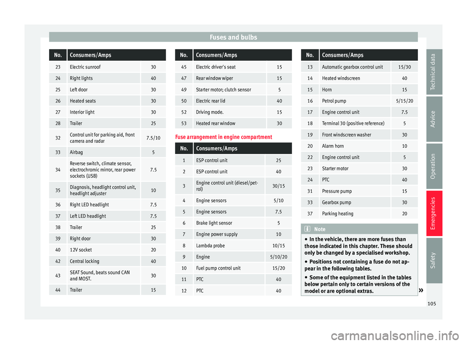
Fuses and bulbsNo.Consumers/Amps
23Electric sunroof30
24Right lights40
25Left door30
26Heated seats30
27Interior light30
28Trailer25
32Control unit for parking aid, front
camera and radar7.5/10
33Airbag5
34Reverse switch, climate sensor,
electrochromic mirror, rear power
sockets (USB)7.5
35Diagnosis, headlight control unit,
headlight adjuster10
36Right LED headlight7.5
37Left LED headlight7.5
38Trailer25
39Right door30
4012V socket20
42Central locking40
43SEAT Sound, beats sound CAN
and MOST.30
44Trailer15
No.Consumers/Amps
45Electric driver's seat15
47Rear window wiper15
49Starter motor; clutch sensor5
50Electric rear lid40
52Driving mode.15
53Heated rear window30
Fuse arrangement in engine compartment
No.Consumers/Amps
1ESP control unit25
2ESP control unit40
3Engine control unit (diesel/pet-
rol)30/15
4Engine sensors5/10
5Engine sensors7.5
6Brake light sensor5
7Engine power supply10
8Lambda probe10/15
9Engine5/10/20
10Fuel pump control unit15/20
11PTC40
12PTC40
No.Consumers/Amps
13Automatic gearbox control unit15/30
14Heated windscreen40
15Horn15
16Petrol pump5/15/20
17Engine control unit7.5
18Terminal 30 (positive reference)5
19Front windscreen washer30
20Alarm horn10
22Engine control unit5
23Starter motor30
24PTC40
31Pressure pump15
33Gearbox pump30
37Parking heating20
Note
● In the v ehic
le, there are more fuses than
those indicated in this chapter. These should
only be changed by a specialised workshop.
● Positions not containing a fuse do not ap-
pear in the fo
llowing tables.
● Some of the equipment listed in the tables
below pert
ain only to certain versions of the
model or are optional extras. » 105
Technical data
Advice
Operation
Emergencies
Safety
Page 109 of 348
Fuses and bulbs
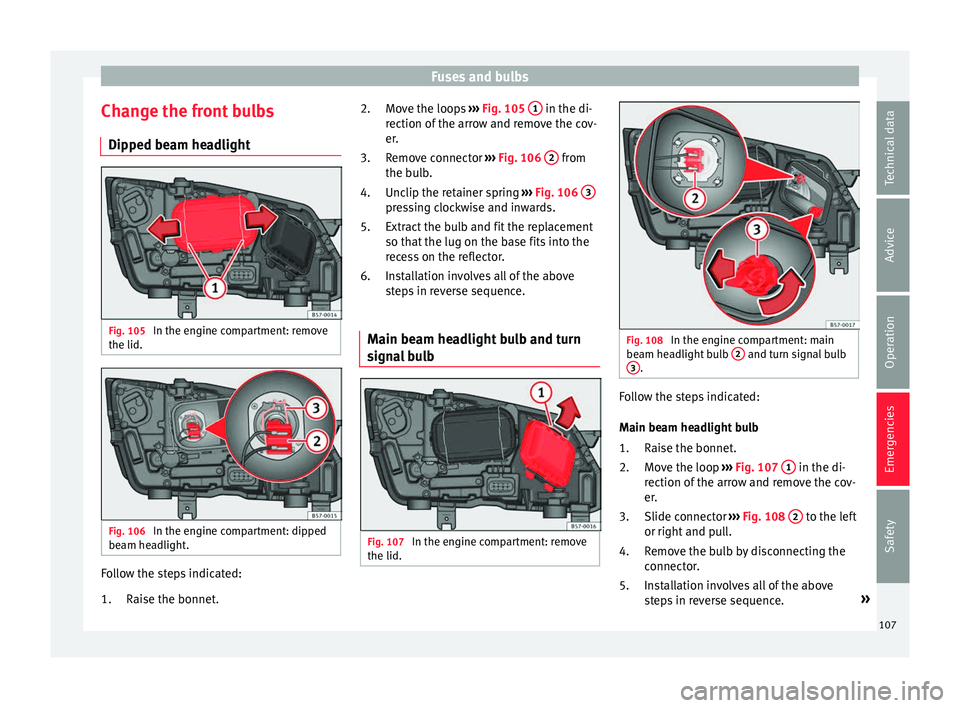
Change the front bulbs Dip ped be
am he
adlightFig. 105
In the engine compartment: remove
the lid. Fig. 106
In the engine compartment: dipped
be am he
a
dlight. Follow the steps indicated:
Rai
se the bonnet
.
1. Move the loops
›››
Fig. 105 1 in the di-
r ection of
the arr
ow and remove the cov-
er.
Remove connector ››› Fig. 106 2 from
the b u
l
b.
Unclip the retainer spring ››› Fig. 106 3 pressing clockwise and inwards.
Extr
act
the b
ulb and fit the replacement
so that the lug on the base fits into the
recess on the reflector.
Installation involves all of the above
steps in reverse sequence.
Main beam headlight bulb and turn
signa
l bulb Fig. 107
In the engine compartment: remove
the lid. 2.
3.
4.
5.
6.
Fig. 108
In the engine compartment: main
be am he
a
dlight bulb 2 and turn signal bulb
3 .
Follow the steps indicated:
M
ain be
am he
adlight bulb
Raise the bonnet.
Move the loop ››› Fig. 107 1 in the di-
r ection of
the arr
ow and remove the cov-
er.
Slide connector ››› Fig. 108 2 to the left
or right and p
u
ll.
Remove the bulb by disconnecting the
connector.
Installation involves all of the above
steps in reverse sequence. »
1.
2.
3.
4.
5.
107
Technical data
Advice
Operation
Emergencies
Safety