technical data Seat Ateca 2018 Workshop Manual
[x] Cancel search | Manufacturer: SEAT, Model Year: 2018, Model line: Ateca, Model: Seat Ateca 2018Pages: 348, PDF Size: 7.32 MB
Page 169 of 348
Transport and practical equipment
●
Alw a
ys secure the net hooks properly so
that they do not suddenly release from the
fastening rings when hooking or unhooking
them.
● On hooking or unhooking them, protect
your eye
s and face in case the hooks are re-
leased suddenly.
● Always hook up the net bag hooks in the
desc
ribed order. If a hook is unexpectedly re-
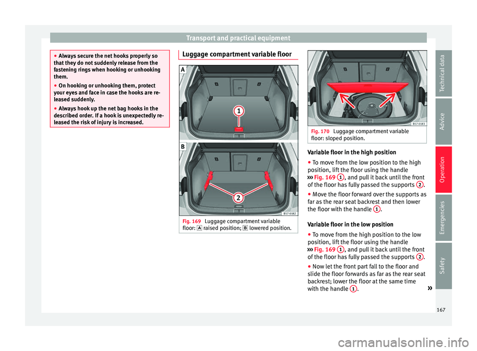
leased the risk of injury is increased. Luggage compartment variable floor
Fig. 169
Luggage compartment variable
floor: r ai
sed po
sition; lowered position. Fig. 170
Luggage compartment variable
floor: sloped po s
ition. Variable floor in the high position
●
To move from the low position to the high
po s
ition, lif
t the floor using the handle
››› Fig. 169 1 , and pull it back until the front
of the floor h
a
s fully passed the supports 2 .
● Move the floor forward over the supports as
f ar a
s
the rear seat backrest and then lower
the floor with the handle 1 .
V ari
ab
le floor in the low position
● To move from the high position to the low
position, lif
t the floor using the handle
››› Fig. 169 1 , and pull it back until the front
of the floor h
a
s fully passed the supports 2 .
● Now let the front part fall to the floor and
s lide the floor f
or
wards as far as the rear seat
backrest; lower the floor at the same time
with the handle 1 .
»
167
Technical data
Advice
Operation
Emergencies
Safety
Page 171 of 348
Transport and practical equipment
●
Vehic l
e height is increased by the installa-
tion of cross bars or a roof carrier system and
the load secured on them. For this purpose,
check that your vehicle's height does not sur-
pass the headspace limit, for example, for un-
derpasses or for entering garage doors.
● Cross bars, the roof carrier system and the
load sec
ured on them should not interfere
with the roof aerial or hamper the path of the
panoramic sun roof and the rear lid.
● On opening the rear lid make sure that it
does not
knock into the roof load. For the sake of the environment
When cross bars and a roof carrier system are
ins t
alled, the increased air resistance means
that the vehicle uses more fuel. Attach the cross bars and the roof car-
rier sy
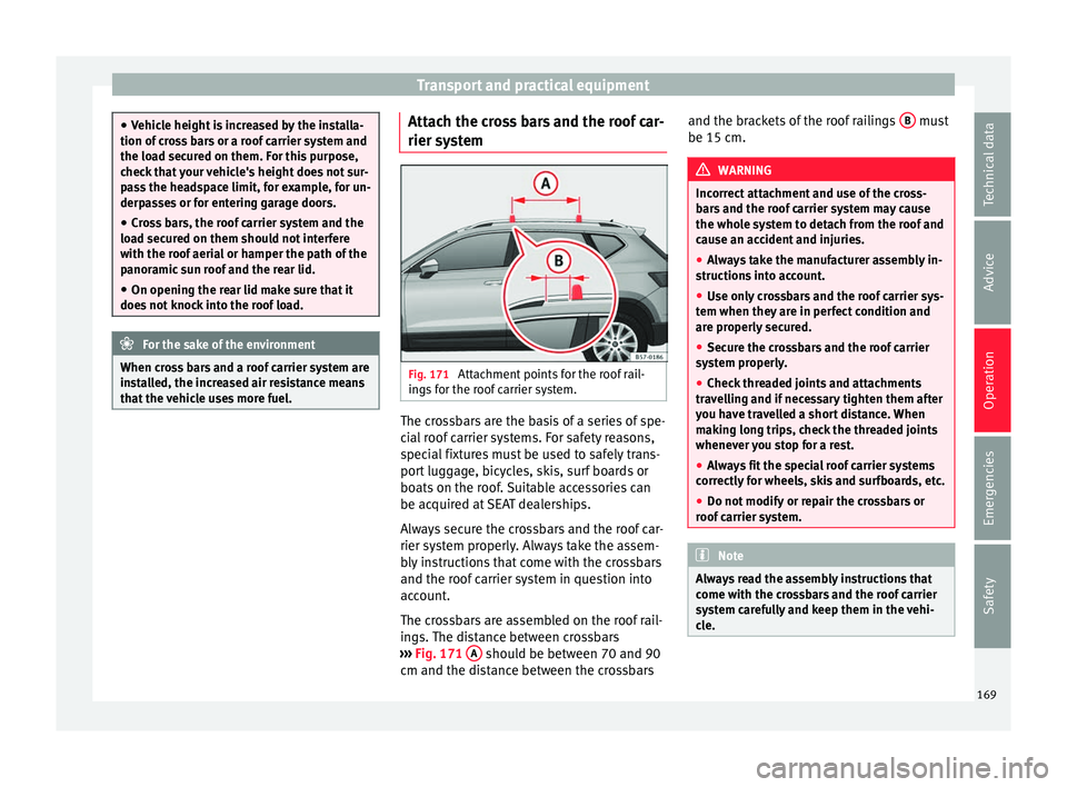
s
t
em Fig. 171
Attachment points for the roof rail-
in g
s
for the roof carrier system. The crossbars are the basis of a series of spe-
c
i
al
roof carrier systems. For safety reasons,
special fixtures must be used to safely trans-
port luggage, bicycles, skis, surf boards or
boats on the roof. Suitable accessories can
be acquired at SEAT dealerships.
Always secure the crossbars and the roof car-
rier system properly. Always take the assem-
bly instructions that come with the crossbars
and the roof carrier system in question into
account.
The crossbars are assembled on the roof rail-
ings. The distance between crossbars
››› Fig. 171 A should be between 70 and 90
c m and the di
s
tance between the crossbars and the brackets of the roof railings
B must
be 15 c m. WARNING
Incorrect attachment and use of the cross-
bar s
and the roof carrier system may cause
the whole system to detach from the roof and
cause an accident and injuries.
● Always take the manufacturer assembly in-
structions
into account.
● Use only crossbars and the roof carrier sys-
tem when they ar
e in perfect condition and
are properly secured.
● Secure the crossbars and the roof carrier
syst
em properly.
● Check threaded joints and attachments
travel
ling and if necessary tighten them after
you have travelled a short distance. When
making long trips, check the threaded joints
whenever you stop for a rest.
● Always fit the special roof carrier systems
correctly
for wheels, skis and surfboards, etc.
● Do not modify or repair the crossbars or
roof c
arrier system. Note
Always read the assembly instructions that
come w ith the c
rossbars and the roof carrier
system carefully and keep them in the vehi-
cle. 169
Technical data
Advice
Operation
Emergencies
Safety
Page 173 of 348

Air conditioning
WARNING
Reduced visibility through the windows in-
cr e
ases the risk of serious accidents.
● Always ensure that all windows are free of
ice and sno
w, and that they are not fogged,
so as to maintain good visibility of everything
outside.
● The maximum heat output required to de-
fros
t windows as quickly as possible is only
available when the engine has reached its
normal running temperature. Only drive when
you have good visibility.
● Always ensure that you use the heating
syst
em, fresh air system, air conditioner and
the heated rear window to maintain good visi-
bility to the outside.
● Never leave the air recirculation on for a
long period of time. If
the cooling system is
switched off and air recirculation mode
switched on, the windows can mist over very
quickly, considerably limiting visibility.
● Switch air recirculation mode off when it is
not requir
ed. WARNING
Stuffy or used air will increase fatigue and re-
duce driv er c
oncentration possibly resulting
in a serious accident.
● Never leave the fresh air fan turned off or
use the air rec
irculation for long periods of
time; the air in the vehicle interior will not be
refreshed. CAUTION
● To r ep
lace the pollen filter, always visit a
service centre.
● Switch the air conditioner off if you think it
may
be broken. This will avoid additional
damage. Have the air conditioner checked by
a specialised workshop.
● Repairs to the air conditioner require spe-
cia
list knowledge and special tools. SEAT rec-
ommends visiting a SEAT Official Service. Note
● When the coo lin
g system is turned off, air
coming from the outside will not be dried. To
prevent fogging of the windows, SEAT recom-
mends leaving the cooling system (compres-
sor) turned on. To do this, press the button . The button lamp should light up.
● The maximum heat output required to de-
fro s
t windows as quickly as possible is only
available when the engine has reached its
normal running temperature.
● Keep the air intake slots in front of the
winds
creen free of snow, ice and leaves to en-
sure heating and cooling are not impaired,
and to prevent the windows from misting
over. Operating the Climatronic through the
E
a
sy
Connect system* 3 Applies to vehicles with a Media System
T ouc
h/Colour. Fig. 172
Easy Connect screen: air conditioner
menu. In the Easy Connect system it is also possible
t
o per
f
orm various adjustments to the Clima-
tronic.
Open the air conditioner menu
● Press the button on the Climatronic
c ontr
o
l panel.
● OR: press the button in Easy Connect.
W ith the r
ot
ating switch select the air con-
ditioner menu and open it.
On the touch screen you can see and change
the current settings, for example, the temper-
ature set for the driver and passenger sides,
the air distribution and the fan speed. »
171
Technical data
Advice
Operation
Emergencies
Safety
Page 175 of 348
Air conditioningFunction button: Function
It enables activation and deactivation of
the PureAir and opens the submenu.
Air conditioning user instructions
The interior cooling system only works when
the engine i
s
running and fan is switched on.
The air conditioner operates most effectively
with the windows and the panoramic sliding
sunroof closed. However, if the vehicle has
heated up after standing in the sun for some
time, the air inside can be cooled more quick-
ly by opening the windows and the panoram-
ic sliding sunroof briefly.
Climatronic: change the temperature unit on
the screen of the radio or on the factory-fit-
ted navigation system
Changing the temperature display from Cel-
sius to Fahrenheit on radio or on the factory- fitted navigation system is done using the
menu on the ins
trument
panel
››› page 36.
The cooling system cannot be activated
If the air conditioning system cannot be
switched on, this may be caused by the fol-
lowing:
● The engine is not running.
● The fan is switched off.
● The air conditioner fuse has blown.
● The outside temperature is lower than ap-
prox
imately +3°C (+38°F).
● The air conditioner compressor has been
temporari
ly switched off because the engine
coolant temperature is too high.
● Another fault in the vehicle. Have the air
conditioner chec
ked by a specialised work-
shop. Special Characteristics
If the humidity and t
emperature outside the
vehicle are high, condensation can drip off
the evaporator in the cooling system and
form a pool underneath the vehicle. This is
normal and does not indicate a leak! Note
After starting the engine, any residual humid-
ity in the air c onditioner c
ould mist over the
windscreen. Switch on the defrost function as
soon as possible to clear the windscreen of
condensation. 173
Technical data
Advice
Operation
Emergencies
Safety
Page 177 of 348
Air conditioning
Functioning mode of automatic air recircula-
tion (air c onditionin
g menu)
W
ith the automatic air recirculation mode ac-
tivated, the entry of fresh air into the cabin
interior is enabled. If the system detects a
high concentration of hazardous substances
in the ambient air, air recirculation mode is
switched on automatically. When the level of
impurities drops to within a normal range, re-
circulation mode is switched off.
The system is unable to detect unpleasant
smells.
The air recirculation will not connect auto-
matically in versions without humidity sensor
and in the following external conditions:
● The outside temperature is lower than +3°C
(+38°F).
● The cooling system is switched off and the
outside temper
ature is below +10°C (+50°F).
● The cooling system is switched off, the out-
side temper
ature is below +15°C (+59°F) and
the windscreen wipers are switched on.
Activation/deactivation of automatic air recir-
culation is done in the air conditioner menu,
under Configuration. WARNING
Observe the safety warnings ›››
in Intro-
duction on pag e 171
. ●
If the c oo
ling system is switched off and air
recirculation mode switched on, the windows
can mist over very quickly, considerably limit-
ing visibility.
● Switch air recirculation mode off when it is
not requir
ed. CAUTION
Do not smoke when air recirculation is
sw itc
hed on in vehicles with an air condition-
er. The smoke taken in could lie on the cool-
ing system vaporiser and on the activated
charcoal cartridge of the dust and pollen fil-
ter, leading to a permanently unpleasant
smell. Note
Climatronic: air recirculation mode is activa-
ted t o pr
event exhaust gas or unpleasant
odours from entering the vehicle interior
when it is in reverse and while the automatic
windscreen wiper is working. Heated windscreen*
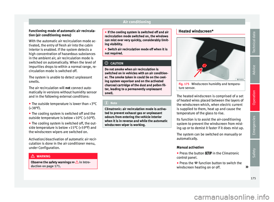
Fig. 175
Windscreen humidity and tempera-
t ur
e sen
sor. The heated windscreen is comprised of a set
of
he
at
ed wires placed between the layers of
the windscreen which, when electric current
is supplied to them, heat up and cause the
temperature of the glass to rise.
Its function is to assist the air-conditioning
system to prevent the windscreen from mist-
ing up or to demist it faster if it does mist up.
The system can be switched on manually or
automatically.
Manual activation
● Press the button in the Climatr
onic
control panel.
● Press the function b
utton to switch the
windscreen heating on or off. »
175
Technical data
Advice
Operation
Emergencies
Safety
Page 179 of 348
Air conditioning
Auxiliary heater (additional
he at
er)*
Intr
oduction The auxiliary heater runs on fuel from the ve-
hicl
e's
tank and can be used while you are
driving and when the vehicle is stationary.
The auxiliary heater can be switched on using
the fast heating button of the air condition-
ing controls, with the remote control or by
previously programming a departure time in
the auxiliary heater menu of the infotainment
system.
In winter, with the auxiliary heater switched
on, you can defog the windscreen and leave
it free of ice and snow (if it is a thin layer) be-
fore you start driving.
If the outside temperature is very high, the
vehicle interior can be ventilated with the en-
gine off using the auxiliary heater. WARNING
Swallowing a battery with a 20 mm diameter
or any other b
utton battery can cause serious
and even fatal injuries within a very short
time.
● Always keep the remote control, keyrings
with batt
eries, the spare batteries, button
batteries and all other batteries over 20 mm
out of reach of children. ●
If y
ou suspect that someone may have
swallowed a battery, seek immediate medical
attention. WARNING
The auxiliary heater exhaust fumes contain
c arbon mono x
ide, an odourless and colour-
less toxic gas. Carbon monoxide can cause
people to lose consciousness. It can also
cause death.
● Never switch on the auxiliary heater or
leav
e it running in enclosed spaces or areas
with no ventilation.
● Never programme the auxiliary heater so
that it
switches itself on and is running in an
enclosed space or an area with no ventila-
tion. WARNING
The components of the auxiliary heater are
extr emely
hot and could cause a fire.
● Always park your vehicle so that no part of
the exhau
st system can come in contact with
easily flammable materials that might be be-
low the vehicle, such as dried grass. CAUTION
Never place food, medicines or other temper-
atur e-
sensitive objects close to the air vents.
Food, medicines and other objects sensitive
to heat or cold may be damaged or made un- suitable for use by the air coming from the
vent
s. Note
After switching the engine on with a 12-volt
b att er
y that is heavily discharged or newly
changed or after a jump start some system
settings (such as the time, the date, the per-
sonalised comfort settings and the program-
ming) might be altered or deleted. Check and
correct these settings once the battery is suf-
ficiently charged. Switching on and off the auxiliary
he
at
er
Switching the auxiliary heater on:
Manually with the fast heating button of the air
conditioner controls. The control lamp of the
button will light up
››› page 170.
Manually with the remote control
››› page 178.
Automatically by programming and activating a
departure time ››› page 179.
Switching the auxiliary heater off:
Manually with the fast heating button of the air
conditioner controls. The control lamp of the
button goes off
››› page 170.
Manually with the remote control
››› page 178.» 177
Technical data
Advice
Operation
Emergencies
Safety
Page 181 of 348
Air conditioning
The battery is located beneath a cover on the
b ac
k
of the remote control.
● To open the cover, lift it slightly at the bot-
tom and slide it
down.
● Remove the old battery.
● Insert the new battery. When doing so, take
into acc
ount the polarity and use batteries of
the same type ››› .
● Replace the battery cover by inserting the
t ab
s
at the top and pressing the bottom.
Range
The receiver is inside the vehicle. The remote
control, when fitted with new batteries, has a
range of several hundred metres. Obstacles
between the remote control and the vehicle,
bad weather conditions and discharged bat-
teries can considerably reduce the range of
the remote control. CAUTION
● The ra dio fr
equency remote control con-
tains electronic components. Therefore, avoid
getting it wet and exposing it to knocks or di-
rect sunlight.
● The use of inappropriate batteries may
damag
e the radio frequency remote control.
For this reason, always replace the used bat-
tery with another of the same voltage, size
and specifications. For the sake of the environment
● Ple a
se dispose of your used batteries cor-
rectly and with respect for the environment.
● The remote control battery may contain
perch
lorate. Observe the legal provisions re-
garding disposal.
● Care should be taken so as not to operate
the remote c
ontrol unintentionally so as to
prevent the auxiliary heater being switched
on accidentally. Programming the auxiliary heater
Before pr
ogramming it, check that the vehi-
c l
e's date and time are set correctly ››› .
The aux i
li
ary heater is programmed in the
Auxiliary heater menu of the infotain-
ment system.
Open the Auxiliary heater menu.
● Press the button in the Clim
atronic
control panel.
● Press the function b
utton.
Function button: function
Switch off: The auxiliary heater is immediately switched
off.
Function button: function
Heat, Ventilate: Set to heat or ventilate the vehicle interi-
or when the auxiliary heater is switched on. By pressing
the function button
, you can select the desired
mode.
Set: Opens the Auxiliary heater menu.
Departure time 1, Departure time 2, Departure time 3:
Three different departure times (hh.mm) may be
programmed. If the auxiliary heater should only
be switched on a certain day of the week, this can
also be selected.
Duration: The duration determines the operating
time of the auxiliary heater when switched on us-
ing the fast heating button
on the air condi-
tioning controls. The duration is also used to cal-
culate the departure time for the manual air con-
ditioner. It can be set between 10 and 60 mi-
nutes at 10-minute intervals.
This returns to the main menu.
The programmed departure time determines
the ap
pr
o
ximate time it should take to reach
the temperature set in the vehicle. The start
of the heating operation is determined auto-
matically depending on the outside tempera-
ture.
Checking the programming
When a departure time is activated and the
ignition is switched off the control lamp of
the fast heating button lights up for ap-
proximately 10 seconds. »
179
Technical data
Advice
Operation
Emergencies
Safety
Page 183 of 348
Driving
Driving St ar
tin
g and stopping the en-
gine
Switching the ignition on and starting
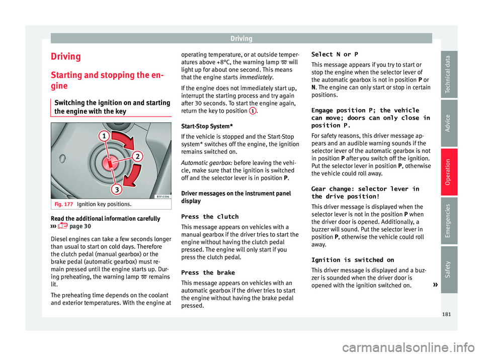
the engine with the key Fig. 177
Ignition key positions. Read the additional information carefully
› ›
›
page 30
Diesel engines can take a few seconds longer
than usual to start on cold days. Therefore
the clutch pedal (manual gearbox) or the
brake pedal (automatic gearbox) must re-
main pressed until the engine starts up. Dur-
ing preheating, the warning lamp remains
lit.
The preheating time depends on the coolant
and exterior temperatures. With the engine at operating temperature, or at outside temper-
ature
s above +8°C, the warning lamp will
light up for about one second. This means
that the engine starts immediately.
If the engine does not immediately start up,
interrupt the starting process and try again
after 30 seconds. To start the engine again,
return the key to position 1 .
St ar
t
-Stop System*
If the vehicle is stopped and the Start-Stop
system* switches off the engine, the ignition
remains switched on.
Automatic gearbox: before leaving the vehi-
cle, make sure that the ignition is switched
off and the selector lever is in position P.
Driver messages on the instrument panel
display
Press the clutch
This message appears on vehicles with a
manual gearbox if the driver tries to start the
engine without having the clutch pedal
pressed. The engine will only start if you
press the clutch pedal.
Press the brake This message appears on vehicles with an
automatic gearbox if the driver tries to start
the engine without having the brake pedal
pressed. Select N or P
This me
ssage appears if you try to start or
stop the engine when the selector lever of
the automatic gearbox is not in position P or
N. The engine can only start or stop in certain
positions.
Engage position P; the vehicle
can move; doors can only close in
position P.For safety reasons, this driver message ap-
pears and an audible warning sounds if the
selector lever of the automatic gearbox is not
in position P after you switch off the ignition.
Put the selector lever in position P, otherwise
the vehicle could roll away.
Gear change: selector lever in
the drive position! This driver message is displayed when the
selector lever is not in the position P when
the driver door is opened. Additionally, a
buzzer will sound. Put the selector lever in
position P, otherwise the vehicle could roll
away.
Ignition is switched on
This driver message is displayed and a buz-
zer is sounded when the driver door is
opened with the ignition switched on. »
181
Technical data
Advice
Operation
Emergencies
Safety
Page 185 of 348
Driving
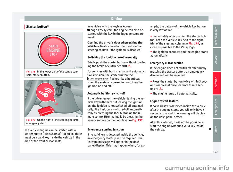
Starter button* Fig. 178
In the lower part of the centre con-
so l
e: s
tarter button. Fig. 179
On the right of the steering column:
emer gency
start. The vehicle engine can be started with a
s
t
ar
ter button (Press & Drive). To do so, there
must be a valid key inside the vehicle in the
area of the front or rear seats. In vehicles with the Keyless Access
›››
page 125 system, the engine can also be
started with the key in the luggage compart-
ment.
Opening the driver's door when exiting the
vehicle activates the electronic lock on the
steering column if the ignition is disabled.
Switching the ignition on/off manually
Briefly push the starter button without touch-
ing the brake or clutch pedal ››› .
F or
v
ehicles with both manual and automatic
transmission, the starter button text START ENGINE STOP flashes like a heartbeat
when the sy s
t
em is preset for switching the
ignition on and off.
Automatic ignition switch-off
If the driver leaves the vehicle, taking the ve-
hicle key with them but leaving the ignition
on, the ignition is not switched off automati-
cally. The ignition is switched off automati-
cally by pressing the lock button on the re-
mote control or manually by pressing the
sensor surface on the door lever ››› Fig. 132
Emergency starting function
If no valid key is detected inside the vehicle,
an emergency start-up will be required. The
relevant message will appear in the dash
panel display. This may happen when, for ex- ample, the battery of the vehicle key button
is
very low or flat:
● Immediately after pushing the starter but-
ton, keep the
vehicle key next to the right
trim of the steering column ››› Fig. 179, as
close as possible to the Kessy logo.
● The ignition connects and the engine starts
automatic
ally.
Emergency disconnection
If the engine does not switch off after briefly
pressing the starter button, an emergency
disconnect will be required:
● Press the starter button twice within 3 sec-
onds or pr
ess it once for more than 1 sec-
ond ››› .
● The engine turns off automatically.
En gine r
e
start feature
If no valid key is detected inside the vehicle
after the engine stops, you will only have 5
seconds to restart it. A warning will display
on the dash panel screen.
After this interval, it will not be possible to
start the engine without a valid key inside
the vehicle. »
183
Technical data
Advice
Operation
Emergencies
Safety
Page 187 of 348
Driving
●
Never u se s
prays to cold start the engine. CAUTION
● The s tar
ter motor or the engine may be
damaged if you try to start the engine while
driving or if you restart it immediately after
switching it off.
● If the engine is cold, avoid high engine
speeds, p
ushing the engine too hard and rap-
id acceleration.
● Do not start the engine by pushing the ve-
hicle or t
owing it. Unburnt fuel could enter
the catalytic converter and damage it. Note
● Do not w ait
until the engine warms up with
the vehicle stationary; if you have good visi-
bility through the windows, start driving im-
mediately. This helps the engine reach oper-
ating temperature faster and reduces emis-
sions.
● Electrical components with a high power
cons
umption are switched off temporarily
when the engine starts.
● When starting with a cold engine, noise
level
s may briefly increase. This is quite nor-
mal, and no cause for concern.
● When the outside temperature is below
+5°C (+41°F), if the en
gine is diesel, some
smoke may appear under the vehicle when
the fuel-operated auxiliary heater is on. Stopping the engine
3 Valid for vehicles: with Keyless Access
StepSwitch off the engine with the starter
button
››› page 183.
1.Stop the vehicle completely ››› .
2.Press and hold the brake pedal until the step
4 is performed.
3.If you are driving an automatic vehicle, place
the selector lever in position P.
4.Connect the electronic parking brake
››› page 186.
5.
Briefly press the start-up button ››› Fig. 178.
The START ENGINE STOP button blinks again. If
the engine fails to switch off, perform an
emergency disconnect ››› page 183.
6.If the vehicle is equipped with a manual
gearbox, put it into 1st or reverse. WARNING
Never switch off the engine while the vehicle
is mo
ving. This could cause loss of control of
the vehicle, accidents and serious injury.
● The airbags and belt tensioners do not
work when the ignition i
s switched off.
● The brake servo does not work with the en-
gine off. Ther
efore, you need to press the
break pedal harder to brake the vehicle. ●
Po w
er steering does not work when the en-
gine is not running. You need more strength
to steer when the engine is switched off.
● If the ignition is switched off, the steering
column c
ould be locked, making it impossible
to control the vehicle. CAUTION
If the engine is made to work hard for a long
time, it ma
y overheat after being switched
off. To prevent damage to the engine before
switching it off, leave it idle for approx. 2 mi-
nutes in neutral. Note
After switching off the engine, the cooling fan
ma y
continue to operate in the engine com-
partment for a few more minutes, even with
the ignition off. The radiator fan is automati-
cally switched off. “My Beat” Function
For vehicles with a convenience key there is
the “M
y
B
eat” function. This feature provides
an additional indication of the vehicle igni-
tion system.
When accessing the vehicle, e.g. by opening
the doors with the remote control, the START ENGINE STOP button flashes, calling at-
t ention t
o the r
elevant starter system button. »
185
Technical data
Advice
Operation
Emergencies
Safety