technical data Seat Ateca 2018 Service Manual
[x] Cancel search | Manufacturer: SEAT, Model Year: 2018, Model line: Ateca, Model: Seat Ateca 2018Pages: 348, PDF Size: 7.32 MB
Page 149 of 348
Lights and visibility
● When the driv er
s
of other oncoming vehi-
cles (such as a truck) can see over a guard
rail in the centre of the road.
● If the camera is damaged or the power sup-
ply i
s cut off.
● In fog, snow and heavy rain.
● With dust and sand turbulence.
● With loose gravel in the field of vision of
the camera.
● When the fiel
d of vision of the camera is
mist
ed up, dirty or covered by stickers, snow,
ice, etc. WARNING
The convenience features of the main beam
as s
ist should not encourage the taking of
risks. The system is not a replacement for
driver concentration.
● You are always in control of the main beam
and adaptin
g it to the light, visibility and traf-
fic conditions.
● It is possible that the main beam headlight
contro
l does not recognise all driving situa-
tions and is limited under certain circumstan-
ces.
● When the field of vision of the camera is
dirty, c
overed or damaged, operation of the
main beam control may be affected. This also
applies when changes are made to the vehi- cle lighting system, for example, if additional
hea
dlight
s are installed. CAUTION
To avoid affecting the operation of the sys-
t em, t ak
e the following points into considera-
tion:
● Clean the field of vision of the camera regu-
larly and m
ake sure it is free of snow and ice.
● Do not cover the field of vision of the cam-
era.
● Check
that the windscreen is not damaged
in the area of
the field of vision of the camera. Note
Main beam and headlight flasher can be
turned on and off m
anually at any time with
the turn signal and main beam lever
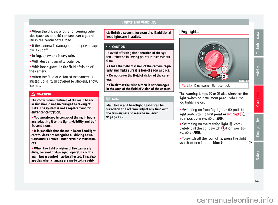
››› page 145. Fog lights
Fig. 143
Dash panel: light control. The warning lamps
or also sho
w
, on the
light switch or instrument panel, when the
fog lights are on.
● Switching on front fog lights* : pul
l the
light switch to the first point ››› Fig. 143 1 ,
fr om po
s
itions , or .
● Switching on the rear fog light : com-
pl
etely pull the light switch 2 from position
, or .
● To sw
itch off the fog lights, press the light
switc
h or turn it to position .»
147
Technical data
Advice
Operation
Emergencies
Safety
Page 151 of 348
Lights and visibility
Function “Leaving Home” The “Leaving Home” function is only availa-
bl
e f
or vehicles with a light and rain sensor
(rotary light switch in position ).
This function may be connected/disconnec-
ted through the radio menu. The “Leaving
Home” function switch-off delay may also be
set (default: 30 sec).
Vehicle with halogen headlights
In the “Leaving Home” function, the daytime
running lights (DRL), the rear side lights and
the licence plate lights are switched on.
Vehicle with full-LED headlights
In the “Leaving Home” function, the dipped
beams, the daytime running lights (DRL), the
rear side lights, the number plate lights and
the courtesy lights in the rear view mirror
(“Welcome Light”) switch on.
Activation
● When the vehicle is unlocked using the re-
mote c ontr
ol.
● The “Leaving Home” function is only activa-
ted when the rot
ary light switch is in position
and the light sensor detects darkness.
Deactivation
● When the “Leaving Home” delay period
ends (def
ault: 30 sec). ●
When the vehic
le is locked using the re-
mote control.
● When the light control is switched into a
position other th
an .
● With the ignition is switched on.
Welcome light* 3
Valid for vehicles with a light and rain sensor
(light sw
itch in position ) and Full LED head-
lights.
The Welcome light is a light located on the
exterior mirrors facing the ground which is
switched on or off if the lights control is in
the position and the “Coming Home” /
“Leaving Home” function is switched on or
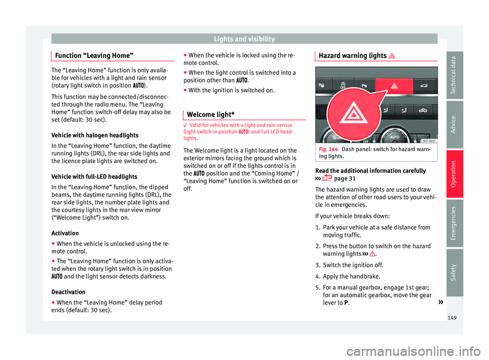
off. Hazard warning lights
Fig. 144
Dash panel: switch for hazard warn-
in g lights. Read the additional information carefully
› ›
›
page 31
The hazard warning lights are used to draw
the attention of other road users to your vehi-
cle in emergencies.
If your vehicle breaks down:
1. Park your vehicle at a safe distance from movin
g traffic.
2. Press the button to switch on the hazard warning lights
››› .
3. Switch the ignition off.
4. Apply the handbrake.
5. For a manual gearbox, engage 1st gear; for an aut
om
atic gearbox, move the gear
lever to P. »
149
Technical data
Advice
Operation
Emergencies
Safety
Page 153 of 348
Lights and visibility
The light distribution of the halogen and full-
LED he a
dlights
allows the specific “tourist
light” values to be met without the need for
stickers or changes in the settings. Note
“Tourist light” is only allowed temporarily. If
you ar e p
lanning a long stay in a country that
drives on the other side, you should take the
vehicle to an Authorised Technical Service to
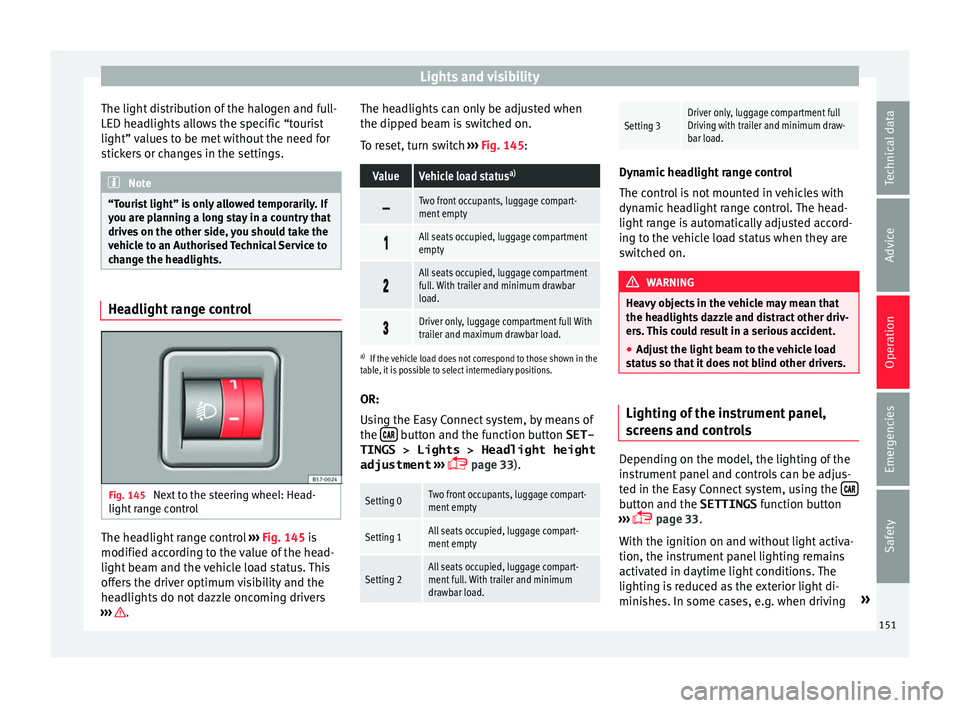
change the headlights. Headlight range control
Fig. 145
Next to the steering wheel: Head-
light r
an
ge control The headlight range control
››
›
Fig. 145 is
modified according to the value of the head-
light beam and the vehicle load status. This
offers the driver optimum visibility and the
headlights do not dazzle oncoming drivers
››› . The headlights can only be adjusted when
the dip
ped be
am i
s switched on.
To reset, turn switch ››› Fig. 145:
ValueVehicle load status a)
Two front occupants, luggage compart-
ment empty
All seats occupied, luggage compartment
empty
All seats occupied, luggage compartment
full. With trailer and minimum drawbar
load.
Driver only, luggage compartment full With
trailer and maximum drawbar load.
a)
If the vehicle load does not correspond to those shown in the
table, it is possible to select intermediary positions.
OR:
Using the Easy Connect system, by means of
the button and the function button SET-
TINGS > Lights > Headlight height
adjustment
› ›
›
page 33).
Setting 0Two front occupants, luggage compart-
ment empty
Setting 1All seats occupied, luggage compart-
ment empty
Setting 2All seats occupied, luggage compart-
ment full. With trailer and minimum
drawbar load.
Setting 3Driver only, luggage compartment full
Driving with trailer and minimum draw-
bar load. Dynamic headlight range control
The contr
o
l is not mounted in vehicles with
dynamic headlight range control. The head-
light range is automatically adjusted accord-
ing to the vehicle load status when they are
switched on. WARNING
Heavy objects in the vehicle may mean that
the hea dlight
s dazzle and distract other driv-
ers. This could result in a serious accident.
● Adjust the light beam to the vehicle load
stat
us so that it does not blind other drivers. Lighting of the instrument panel,
s
c
r
eens and controls Depending on the model, the lighting of the
in
s
trument
panel and controls can be adjus-
ted in the Easy Connect system, using the button and the SETTINGS
fu
nction b
utton
››› page 33.
With the ignition on and without light activa-
tion, the instrument panel lighting remains
activated in daytime light conditions. The
lighting is reduced as the exterior light di-
minishes. In some cases, e.g. when driving »
151
Technical data
Advice
Operation
Emergencies
Safety
Page 155 of 348
Lights and visibility
Vanity mirror light
Ther e m
a
y be a vanity mirror, with a cover, on
the rear of the sun visor. When the cover is
opened 2 a light comes on.
The l amp g
oe
s out when the vanity mirror
cover is closed or the sun visor is pushed
back up. WARNING
Folded sun blinds can reduce visibility.
● Always store sun blinds and visors in their
hous in
g when not in use. Note
The light above the sun visor automatically
swit c
hes off after a few minutes in certain
conditions. This prevents the battery from
discharging. Windscreen wiper and window
w
iper sy
s
tems
Window wiper lever Read the additional information carefully
› ›
›
page 32 CAUTION
If the ignition is switched off with the wind-
sc r
een wipers active, they complete their
wipe before returning to the rest position.
When switching the ignition back on, the
windscreen wiper will continue to operate at
the same wiping level. Ice, snow and other
obstacles on the windscreen may damage the
wiper and the windscreen wiper motor.
● If necessary, remove snow and ice from the
winds
creen wipers before starting your jour-
ney.
● Carefully lift the frozen windscreen wipers
from the gla
ss. SEAT recommends a de-icer
spray for this operation.
● Do not switch on the windscreen wipers if
the winds
creen is dry. Cleaning with the
windscreen wipers while dry can cause dam-
age.
● In icy conditions, always check that the
wiper bl
ades are not frozen to the glass be-
fore using the wipers. In cold weather, it may
help to leave the vehicle parked with the wip-
ers in service position ›››
page 71. Note
● The wind s
creen and window wipers only
function when the ignition is switched on and
the bonnet or rear lid, respectively, are
closed.
● The interval wipe speed varies according to
the vehic
le speed. The faster the vehicle is moving, the more often the windscreen is
cl
e
aned.
● The rear wiper is automatically switched on
when the winds
creen wiper is on and the car
is in reverse gear. Windscreen wiper functions
Windscreen wiper performance in different sit-
uations
If the vehicle is at a
standstillThe activated position provision-
ally changes to the previous posi-
tion.
During automatic
wipe
The air conditioner comes on for
approximately 30 seconds in air
recirculation mode to prevent the
smell of the windscreen washer
fluid entering the inside the vehi-
cle.
For the interval wipe
Intervals between wipes depend
on the vehicle's speed. The high-
er the vehicle speed the shorter
the intervals.
Heated windscreen washer jets*
The he
atin
g on
ly thaws the frozen jets, it
does not thaw the water in the washer hoses.
When the ignition is switched on the heated
windscreen washer jets automatically adjust
the heat depending on the ambient tempera-
ture. »
153
Technical data
Advice
Operation
Emergencies
Safety
Page 157 of 348
Lights and visibility
reduce the effectiveness of the rain sensor or
m ak
e it
react more slowly, later or not at all.
● Cracked windscreen: the impact of a stone
wil
l trigger a single wipe cycle with the rain
sensor on. Next the rain sensor detects the
reduction in the sensitive surface area and
adapts accordingly. The behaviour of the sen-
sor will vary with the size of the damage
caused by the stone. WARNING
The rain sensor may not detect enough rain
to sw it
ch on the wipers.
● If necessary, switch on the wipers manually
when water on the w
indscreen obstructs visi-
bility. Note
● Cle
an the sensitive surface of the rain sen-
sor regularly and check the blades for dam-
age ››› Fig. 148 (arrow).
● To remove wax and coatings, we recom-
mend a window c
leaner containing alcohol.Mirror
Anti-d azz
l
e rear view mirrorIt is dangerous to drive if you cannot see
c
l
e
arly through the rear window. Rear view mirror with automatic anti-dazzle
function*
The anti-d
azzle function is activated every
time the ignition is switched on.
When the anti-dazzle function is enabled, the
interior rear vision mirror will darken auto-
matically according to the amount of light it
receives. The anti-dazzle function is cancel-
led if reverse gear is engaged. WARNING
In the event that an automatic anti-dazzle
re ar
vision mirror breaks, an electrolyte fluid
may leak. This could cause irritation to the
skin, eyes and respiratory organs. If you
come into contact with this liquid, it must be
rinsed with large quantities of water. If neces-
sary, get medial help. CAUTION
In the event that an automatic anti-dazzle
re ar
vision mirror breaks, an electrolyte fluid
may leak. This liquid attacks plastic surfaces.
Clean it with a wet sponge as soon as possi-
ble. Note
● If the light inc
ident in the interior rear vi-
sion mirror is obstructed (e.g. with the sun
blind*), the anti-dazzle rear vision mirror with
automatic setting will not operate perfectly. ●
When the interior light s
are on or reverse
gear engaged, the mirrors do not darken with
automatic adjustment for anti-dazzle posi-
tion. Adjusting the exterior rear-view mir-
ror
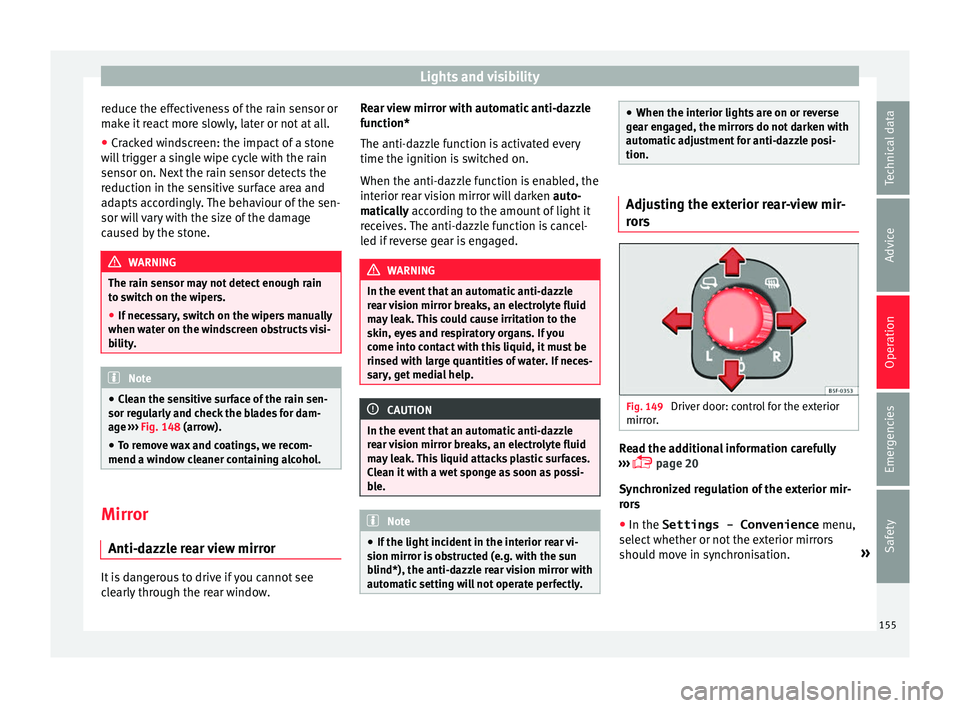
s Fig. 149
Driver door: control for the exterior
mirr or
. Read the additional information carefully
› ›
›
page 20
Synchronized regulation of the exterior mir-
rors
● In the Settings - Convenience menu,
select whether or not
the exterior mirrors
should move in synchronisation. »
155
Technical data
Advice
Operation
Emergencies
Safety
Page 159 of 348
Seats and head restraints
Electric driver's seat adjustment* Read the additional information carefully
›› ›
page 19 WARNING
● If the el ectric
front seats are used negli-
gently or without paying due attention, it can
cause serious injury.
● The front seats can also be electrically ad-
just
ed when the ignition is switched off. Nev-
er leave a child or any other person who may
need help in the vehicle.
● In the event of an emergency, electrical ad-
justment
can be stopped by pressing any
control. CAUTION
To avoid damaging the electrical components
of the fr ont
seats, please refrain from kneel-
ing on the seat or applying sharp pressure at
a single point to the seat cushion and back-
rest. Note
● It m a
y not be possible to electrically adjust
the seat if the vehicle battery is very low.
● If the engine is started while the seats are
being electric
ally adjusted, the adjustment
will stop. Adjusting the front head restraints
Read the additional information carefully
›› ›
page 19
Adjust the head restraint ›››
page 19 so
that as far as possible the top of the head re-
straint is level with the top of your head.
When this is not possible, try to get as close
as possible to this position.
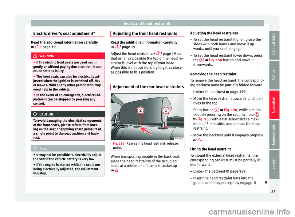
Adjustment of the rear head restraints Fig. 150
Rear centre head restraint: release
point . When transporting people in the back seat,
p
l
ac
e the head restraints of the occupied
seats at a minimum of the next socket up
››› .Adjusting the head restraints
– To set the head restraint higher, grasp the
side
s
with both hands and move it up-
wards, until you see it engage.
– To set the head restraint lower down, press
the 1
› ››
Fig. 150
b
utton and move it
downwards.
Removing the head restraint
To remove the head restraint, the correspond-
ing backrest must be partially folded forward. – Unlock the backrest ›››
page 159.
– Move the head restraint upwards until it ar-
rives
to the top.
– Press button 1
› ›
› Fig. 150
, while simulta-
neously pressing on the security hole 2 ›››
Fig. 150 with a fl at
screwdriver a maxi-
mum of 5 mm wide, and remove the head
restraint.
– Move the backrest until it engages properly
›› ›
.
Fittin g the he
a
d restraint
To mount the external head restraints, the
corresponding backrest must be partially fol-
ded forward.
– Unlock the backrest ›››
page 159.
– Insert the head restraint bars into the
guides u
ntil they perceptibly engage. It »
157
Technical data
Advice
Operation
Emergencies
Safety
Page 161 of 348
Seats and head restraints
●
Do not s it
on the seat with clothing that is
wet or damp.
● Do not leave clothing that is wet or damp
on the seat.
● Do not
spill liquid on the seat. CAUTION
● To av oid d
amaging the heating elements of
the seat heaters, please do not kneel on the
seat or apply sharp pressure to a single point
on the seat cushion or backrest.
● Liquids, sharps objects and insulating ma-
teria
ls (e.g. covers or child seats) can damage
the seat heating.
● In the event of smells, switch off the seat
heating immedi
ately and have it inspected by
a specialised workshop. For the sake of the environment
The seat heating should remain on only when
needed. Otherw i
se, it is an unnecessary fuel
waste. Front centre armrest
The centre armrest can be adjusted to various
l
ev
el
s.
Adjusting the centre armrest – To adjust the tilt, lift the armrest from the
star
ting position so that it is engaged. –
To ret
urn the armrest to the starting posi-
tion, remove the armrest from the upper
fixed position and lower it.
The armrest can be moved backwards and
forwards.
Folding down and lifting the rear seat
back
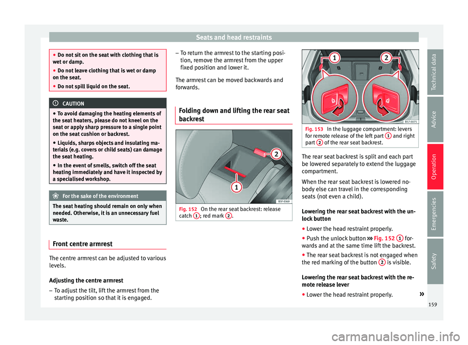
rest Fig. 152
On the rear seat backrest: release
c at
c
h 1 ; red mark
2 . Fig. 153
In the luggage compartment: levers
for r emot
e release of the left part 1 and right
par t
2 of the rear seat backrest.
The rear seat backrest is split and each part
be lo
w
er
ed separately to extend the luggage
compartment.
When the rear seat backrest is lowered no-
body else can travel in the corresponding
seats (not even a child).
Lowering the rear seat backrest with the un-
lock button
● Lower the head restraint properly.
● Push the unlock button ›››
Fig. 152 1 for-
w ar
d
s and at the same time lift the backrest.
● The rear seat backrest is not engaged when
the red mark
ing of the button 2 is visible.
L o
w
ering the rear seat backrest with the re-
mote release lever
● Lower the head restraint properly. »
159
Technical data
Advice
Operation
Emergencies
Safety
Page 163 of 348
Transport and practical equipment
●
Do not driv e w
ith the drawer cover open.
There is an injury risk for passengers if the
cargo is released in case of sudden braking or
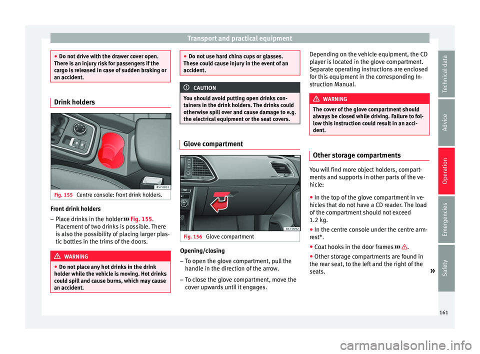
an accident. Drink holders
Fig. 155
Centre console: front drink holders. Front drink holders
– Place drinks in the holder ››
›
Fig. 155.
Placement of two drinks is possible. There
is also the possibility of placing larger plas-
tic bottles in the trims of the doors. WARNING
● Do not p l
ace any hot drinks in the drink
holder while the vehicle is moving. Hot drinks
could spill and cause burns, which may cause
an accident. ●
Do not u se h
ard china cups or glasses.
These could cause injury in the event of an
accident. CAUTION
You should avoid putting open drinks con-
t ainer s
in the drink holders. The drinks could
otherwise spill over and cause damage to e.g.
the electrical equipment or the seat covers. Glove compartment
Fig. 156
Glove compartment Opening/closing
– To open the glove compartment, pull the
handl
e in the dir
ection of the arrow.
– To close the glove compartment, move the
cov
er upwards until it engages. Depending on the vehicle equipment, the CD
pla
yer is located in the glove compartment.
Separate operating instructions are enclosed
for this equipment in the corresponding In-
struction Manual. WARNING
The cover of the glove compartment should
alw a
ys be closed while driving. Failure to fol-
low this instruction could result in an acci-
dent. Other storage compartments
You will find more object holders, compart-
ments
and s
up
ports in other parts of the ve-
hicle:
● In the top of the glove compartment in ve-
hicle
s that do not have a CD reader. The load
of the compartment should not exceed
1.2 kg.
● In the centre console under the centre arm-
res
t*.
● Coat hooks in the door frames ›››
.
● Other storage compartments are found in
the r e
ar se
at, to the left and the right of the
seats. »
161
Technical data
Advice
Operation
Emergencies
Safety
Page 165 of 348
Transport and practical equipment
could impair the driving safety or driving
c h
ar
acteristics of the vehicle by shifting the
centre of gravity.
– Distribute the load evenly in the luggage
compar
tment.
– Place heavy objects as far forward as possi-
ble in the lug
gage compartment.
– Place the heavy objects first.
– Secure heavy objects to the fitted fastening
rings
››› page 165. WARNING
● Loo se lug
gage and other objects in the lug-
gage compartment could cause serious inju-
ries.
● Always stow objects in the luggage com-
partment
and secure them on the fastening
rings.
● Use suitable straps to secure heavy ob-
jects.
● D
uring sudden manoeuvres or accidents,
loose ob
jects can be thrown forward, injuring
vehicle occupants or passers-by. This in-
creased risk of injury will be further increased
if a loose object is struck by an inflating air-
bag. If this happens, objects may shoot out-
ward like a missile. Risk of fatal injury.
● Please note that the centre of gravity may
shift when tr
ansporting heavy objects; this
may affect vehicle handling and lead to an ac-
cident. Therefore, it is essential to adjust your speed and driving style accordingly, to
avoid ac
c
idents.
● Never exceed the allowed axle weights or
allo
wed maximum weight. If said weights are
exceeded, the driving characteristics of the
vehicle may change, leading to accidents, in-
juries and damage to the vehicle.
● Never leave your vehicle unattended, espe-
cia
lly when the rear lid is open. Children
could climb into the luggage compartment,
closing the door behind them; they will be
trapped and run the risk of death.
● Never allow children to play in or around
the vehic
le. Close and lock all the doors and
the rear lid when you leave the vehicle. Be-
fore you lock the vehicle, make sure that
there are no adults or children in the vehicle. Note
● Air cir c
ulation in the vehicle helps reduce
fogging of the windows. Used air escapes
through ventilation slits in the side trim of
the luggage compartment. Ensure that the
ventilation slots are never covered.
● Straps for securing the load to the fasten-
ing ring
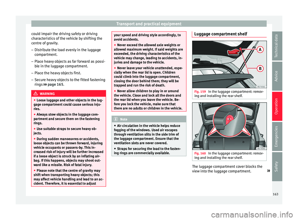
s are commercially available. Luggage compartment shelf
Fig. 159
In the luggage compartment: remov-
in g and in
s
talling the rear shelf. Fig. 160
In the luggage compartment: remov-
in g and in s
talling the rear shelf. The luggage compartment cover blocks the
v
iew int
o the lug
gage compartment. »
163
Technical data
Advice
Operation
Emergencies
Safety
Page 167 of 348
Transport and practical equipment
On the rear seat, behind the central armrest,
ther e i
s
a tailboard for transporting long
items in the interior, such as skis.
To avoid soiling the interior, dirty objects
should be wrapped (e.g. in a blanket) before
they are inserted through the tailboard.
When the armrest is down, nobody may trav-
el in the centre rear seat.
Opening the tailboard
● Lower the centre armrest.
● Pull the release lever in the direction of the
arrow and p
ush the tailboard cover
››› Fig. 163 1 down and forwards.
● Open the rear lid.
● Insert the long objects through the gap
fr om the lug
g
age compartment.
● Secure the objects with the seatbelt.
● Close the rear lid.
Clos
ing the tailboard
● Lift the tailboard cover until it engages. The
red mark
on the luggage compartment side
should never be visible.
● Close the rear lid.
● Lift the centre armrest if necessary. Note
The tailboard can also be opened from the
lugg ag
e compartment. To do so, press the re- lease lever down, in the direction of the ar-
ro
w
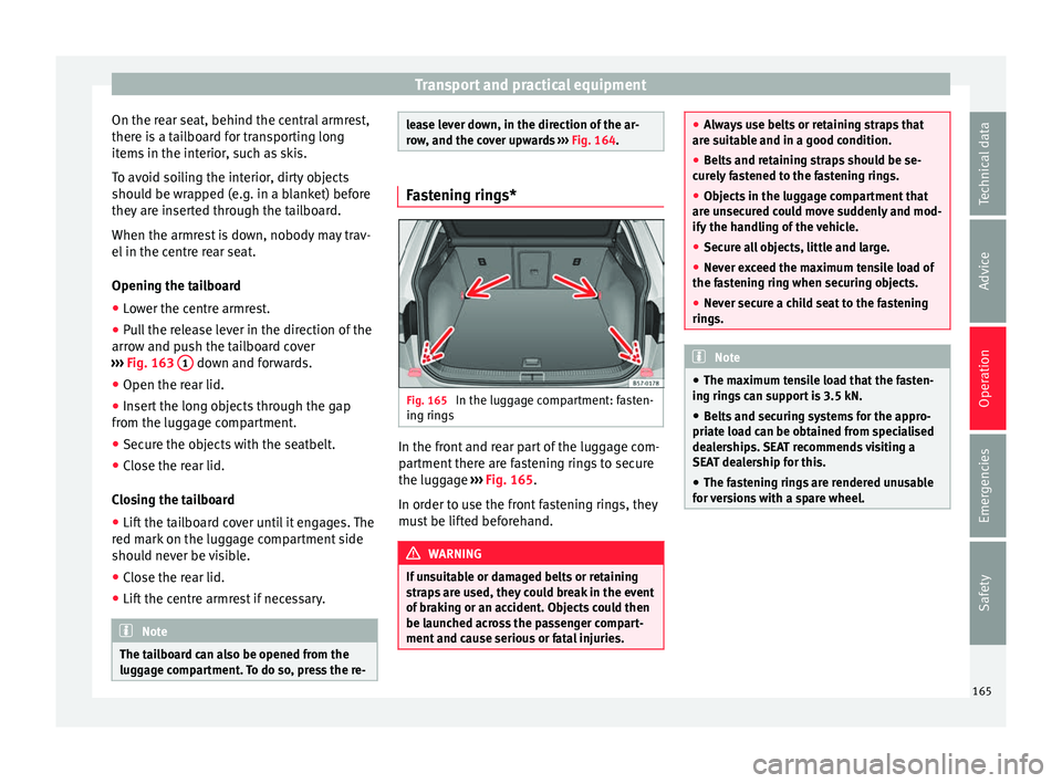
, and the cover upwards ››› Fig. 164. Fastening rings*
Fig. 165
In the luggage compartment: fasten-
in g rin
g
s In the front and rear part of the luggage com-
p
ar
tment
there are fastening rings to secure
the luggage ››› Fig. 165.
In order to use the front fastening rings, they
must be lifted beforehand. WARNING
If unsuitable or damaged belts or retaining
str ap
s are used, they could break in the event
of braking or an accident. Objects could then
be launched across the passenger compart-
ment and cause serious or fatal injuries. ●
Alw a
ys use belts or retaining straps that
are suitable and in a good condition.
● Belts and retaining straps should be se-
curely
fastened to the fastening rings.
● Objects in the luggage compartment that
are un
secured could move suddenly and mod-
ify the handling of the vehicle.
● Secure all objects, little and large.
● Never exceed the maximum tensile load of
the fas
tening ring when securing objects.
● Never secure a child seat to the fastening
rings. Note
● The max imum t
ensile load that the fasten-
ing rings can support is 3.5 kN.
● Belts and securing systems for the appro-
priate lo
ad can be obtained from specialised
dealerships. SEAT recommends visiting a
SEAT dealership for this.
● The fastening rings are rendered unusable
for v
ersions with a spare wheel. 165
Technical data
Advice
Operation
Emergencies
Safety