heating Seat Ateca 2018 Owner's Guide
[x] Cancel search | Manufacturer: SEAT, Model Year: 2018, Model line: Ateca, Model: Seat Ateca 2018Pages: 348, PDF Size: 7.32 MB
Page 179 of 348
Air conditioning
Auxiliary heater (additional
he at
er)*
Intr
oduction The auxiliary heater runs on fuel from the ve-
hicl
e's
tank and can be used while you are
driving and when the vehicle is stationary.
The auxiliary heater can be switched on using
the fast heating button of the air condition-
ing controls, with the remote control or by
previously programming a departure time in
the auxiliary heater menu of the infotainment
system.
In winter, with the auxiliary heater switched
on, you can defog the windscreen and leave
it free of ice and snow (if it is a thin layer) be-
fore you start driving.
If the outside temperature is very high, the
vehicle interior can be ventilated with the en-
gine off using the auxiliary heater. WARNING
Swallowing a battery with a 20 mm diameter
or any other b
utton battery can cause serious
and even fatal injuries within a very short
time.
● Always keep the remote control, keyrings
with batt
eries, the spare batteries, button
batteries and all other batteries over 20 mm
out of reach of children. ●
If y
ou suspect that someone may have
swallowed a battery, seek immediate medical
attention. WARNING
The auxiliary heater exhaust fumes contain
c arbon mono x
ide, an odourless and colour-
less toxic gas. Carbon monoxide can cause
people to lose consciousness. It can also
cause death.
● Never switch on the auxiliary heater or
leav
e it running in enclosed spaces or areas
with no ventilation.
● Never programme the auxiliary heater so
that it
switches itself on and is running in an
enclosed space or an area with no ventila-
tion. WARNING
The components of the auxiliary heater are
extr emely
hot and could cause a fire.
● Always park your vehicle so that no part of
the exhau
st system can come in contact with
easily flammable materials that might be be-
low the vehicle, such as dried grass. CAUTION
Never place food, medicines or other temper-
atur e-
sensitive objects close to the air vents.
Food, medicines and other objects sensitive
to heat or cold may be damaged or made un- suitable for use by the air coming from the
vent
s. Note
After switching the engine on with a 12-volt
b att er
y that is heavily discharged or newly
changed or after a jump start some system
settings (such as the time, the date, the per-
sonalised comfort settings and the program-
ming) might be altered or deleted. Check and
correct these settings once the battery is suf-
ficiently charged. Switching on and off the auxiliary
he
at
er
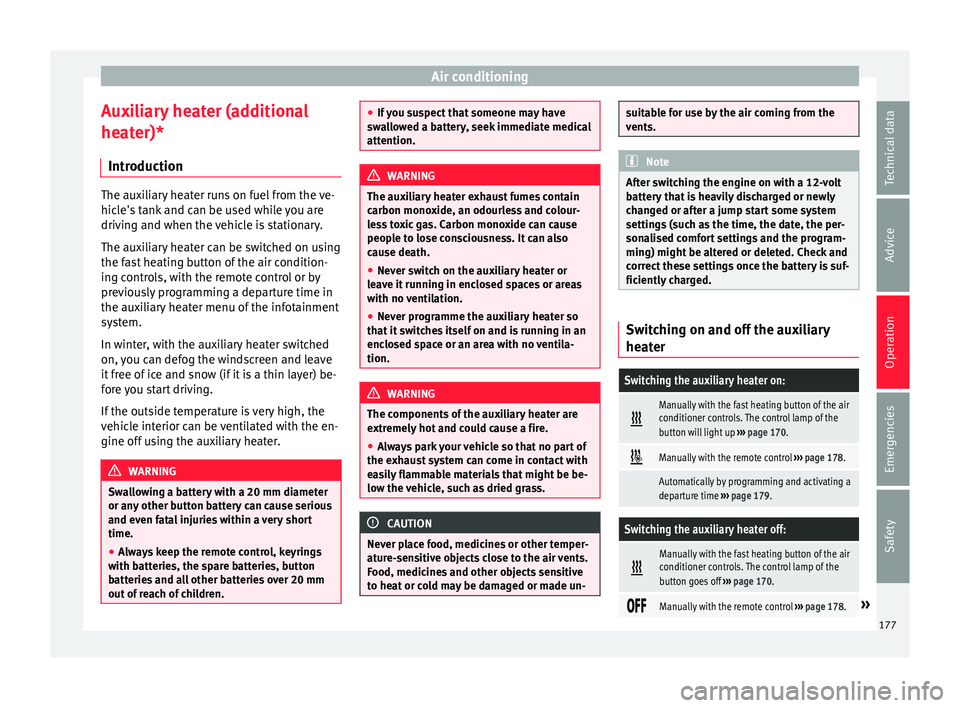
Switching the auxiliary heater on:
Manually with the fast heating button of the air
conditioner controls. The control lamp of the
button will light up
››› page 170.
Manually with the remote control
››› page 178.
Automatically by programming and activating a
departure time ››› page 179.
Switching the auxiliary heater off:
Manually with the fast heating button of the air
conditioner controls. The control lamp of the
button goes off
››› page 170.
Manually with the remote control
››› page 178.» 177
Technical data
Advice
Operation
Emergencies
Safety
Page 181 of 348
Air conditioning
The battery is located beneath a cover on the
b ac
k
of the remote control.
● To open the cover, lift it slightly at the bot-
tom and slide it
down.
● Remove the old battery.
● Insert the new battery. When doing so, take
into acc
ount the polarity and use batteries of
the same type ››› .
● Replace the battery cover by inserting the
t ab
s
at the top and pressing the bottom.
Range
The receiver is inside the vehicle. The remote
control, when fitted with new batteries, has a
range of several hundred metres. Obstacles
between the remote control and the vehicle,
bad weather conditions and discharged bat-
teries can considerably reduce the range of
the remote control. CAUTION
● The ra dio fr
equency remote control con-
tains electronic components. Therefore, avoid
getting it wet and exposing it to knocks or di-
rect sunlight.
● The use of inappropriate batteries may
damag
e the radio frequency remote control.
For this reason, always replace the used bat-
tery with another of the same voltage, size
and specifications. For the sake of the environment
● Ple a
se dispose of your used batteries cor-
rectly and with respect for the environment.
● The remote control battery may contain
perch
lorate. Observe the legal provisions re-
garding disposal.
● Care should be taken so as not to operate
the remote c
ontrol unintentionally so as to
prevent the auxiliary heater being switched
on accidentally. Programming the auxiliary heater
Before pr
ogramming it, check that the vehi-
c l
e's date and time are set correctly ››› .
The aux i
li
ary heater is programmed in the
Auxiliary heater menu of the infotain-
ment system.
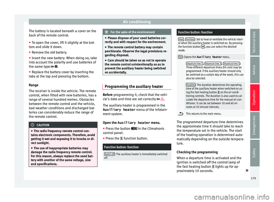
Open the Auxiliary heater menu.
● Press the button in the Clim
atronic
control panel.
● Press the function b
utton.
Function button: function
Switch off: The auxiliary heater is immediately switched
off.
Function button: function
Heat, Ventilate: Set to heat or ventilate the vehicle interi-
or when the auxiliary heater is switched on. By pressing
the function button
, you can select the desired
mode.
Set: Opens the Auxiliary heater menu.
Departure time 1, Departure time 2, Departure time 3:
Three different departure times (hh.mm) may be
programmed. If the auxiliary heater should only
be switched on a certain day of the week, this can
also be selected.
Duration: The duration determines the operating
time of the auxiliary heater when switched on us-
ing the fast heating button
on the air condi-
tioning controls. The duration is also used to cal-
culate the departure time for the manual air con-
ditioner. It can be set between 10 and 60 mi-
nutes at 10-minute intervals.
This returns to the main menu.
The programmed departure time determines
the ap
pr
o
ximate time it should take to reach
the temperature set in the vehicle. The start
of the heating operation is determined auto-
matically depending on the outside tempera-
ture.
Checking the programming
When a departure time is activated and the
ignition is switched off the control lamp of
the fast heating button lights up for ap-
proximately 10 seconds. »
179
Technical data
Advice
Operation
Emergencies
Safety
Page 182 of 348
Operation
WARNING
Never programme the auxiliary heater so that
it sw it
ches itself on and is running in an en-
closed space or an area with no ventilation.
The auxiliary heater exhaust fumes contain
carbon monoxide, an odourless and colour-
less toxic gas. Carbon monoxide can cause
people to lose consciousness. It can also
cause death. Operating instructions
The auxiliary heater exhaust system located
belo
w the
v
ehicle must be kept clear of snow,
mud and other objects. The exhaust fumes
must be able to exit freely. The emissions
generated by the auxiliary heater are re-
moved via an exhaust pipe fitted underneath
the vehicle.
On heating the vehicle interior, depending on
the outside temperature, the warm air is first
directed at the windscreen and then to the
rest of the vehicle interior through the air
vents. Directing the diffusers – towards the
windows for example – can affect air distribu-
tion.
When will the auxiliary heater not be activa-
ted?
● The auxiliary heater requires about as
much po w
er as the dipped beam headlights.
If the 12-volt battery charge is too low, the auxiliary heater switches off automatically
and cannot
be sw
itched on. This avoids prob-
lems when starting the engine.
● The heating must be activated every time
you want
to set off. Similarly, the departure
time must reactivate each time.
● The control lamp (fuel l
evel indicator)
lights up. Note
● Noise s
will be heard while the auxiliary
heater is running.
● When the air humidity is high and the in-
side temper
ature low, condensation from the
heating and ventilating system may evapo-
rate when the auxiliary heater is switched on.
In this case, steam may be released from un-
derneath the vehicle. This does not mean
that there is a vehicle malfunction.
● If the vehicle is tilted, e.g. if parked on a
slope, the operation of
the auxiliary heater
may be restricted if the fuel tank level is low
(just above the reserve level).
● If the auxiliary heater is used a number of
times f
or a long period of time, the 12-volt
battery will lose its charge. To recharge the
battery, the vehicle must be driven for a num-
ber of kilometres from time to time. As a
guideline: The journey should last approxi-
mately as long as the heater was connected.
● At temperatures below +5°C (+41°F), the
auxili
ary heater may switch itself on automat-
ically when the engine is switched on. The auxiliary heater is switched off again after a
cer
t
ain time.180
Page 183 of 348
Driving
Driving St ar
tin
g and stopping the en-
gine
Switching the ignition on and starting
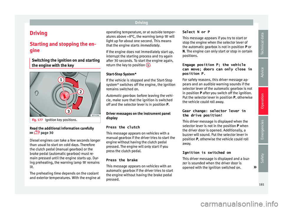
the engine with the key Fig. 177
Ignition key positions. Read the additional information carefully
› ›
›
page 30
Diesel engines can take a few seconds longer
than usual to start on cold days. Therefore
the clutch pedal (manual gearbox) or the
brake pedal (automatic gearbox) must re-
main pressed until the engine starts up. Dur-
ing preheating, the warning lamp remains
lit.
The preheating time depends on the coolant
and exterior temperatures. With the engine at operating temperature, or at outside temper-
ature
s above +8°C, the warning lamp will
light up for about one second. This means
that the engine starts immediately.
If the engine does not immediately start up,
interrupt the starting process and try again
after 30 seconds. To start the engine again,
return the key to position 1 .
St ar
t
-Stop System*
If the vehicle is stopped and the Start-Stop
system* switches off the engine, the ignition
remains switched on.
Automatic gearbox: before leaving the vehi-
cle, make sure that the ignition is switched
off and the selector lever is in position P.
Driver messages on the instrument panel
display
Press the clutch
This message appears on vehicles with a
manual gearbox if the driver tries to start the
engine without having the clutch pedal
pressed. The engine will only start if you
press the clutch pedal.
Press the brake This message appears on vehicles with an
automatic gearbox if the driver tries to start
the engine without having the brake pedal
pressed. Select N or P
This me
ssage appears if you try to start or
stop the engine when the selector lever of
the automatic gearbox is not in position P or
N. The engine can only start or stop in certain
positions.
Engage position P; the vehicle
can move; doors can only close in
position P.For safety reasons, this driver message ap-
pears and an audible warning sounds if the
selector lever of the automatic gearbox is not
in position P after you switch off the ignition.
Put the selector lever in position P, otherwise
the vehicle could roll away.
Gear change: selector lever in
the drive position! This driver message is displayed when the
selector lever is not in the position P when
the driver door is opened. Additionally, a
buzzer will sound. Put the selector lever in
position P, otherwise the vehicle could roll
away.
Ignition is switched on
This driver message is displayed and a buz-
zer is sounded when the driver door is
opened with the ignition switched on. »
181
Technical data
Advice
Operation
Emergencies
Safety
Page 186 of 348
Operation
Automatic deactivation of the ignition on ve-
hic l
e
s with the Start-Stop system
The ignition is switched off automatically
when the vehicle is stopped and the auto-
matic engine shutdown is active, if:
● The driver's seat belt is not fastened,
● the driver does not step on any pedal,
● the driver door is opened.
After aut
omatically turning off the ignition, if
the dipped beam is on, the side light re-
mains on for approx. 30 minutes (if the bat-
tery is sufficiently charged). If the driver locks
the vehicle or manually turns off the light, the
side light goes out. WARNING
Any accidental movement of the vehicle could
re s
ult in serious injury.
● When switching on the ignition, do not
pre
ss the brake or clutch pedal, otherwise
the engine could start immediately. WARNING
If vehicle keys are used negligently or with-
out due c ar
e, this may cause accidents and
serious injury.
● Never leave any key inside the vehicle
when exitin
g. Otherwise, a child or unauthor-
ised person could lock the vehicle, start the
engine or connect the ignition and, in this way, operate electronic equipment (e.g. the
windo
w
s). Note
● Bef or
e leaving the vehicle, always discon-
nect the ignition manually and, if appropri-
ate, take into account the instructions on the
screen of the dash panel.
● If the vehicle is stationary for a long time
with the ignition on, the v
ehicle battery
might be discharged and it might not be pos-
sible to start the engine.
● In diesel vehicles, there may be a delay in
the engine st
arting if it requires preheating.
● If during the STOP phase you press the
STAR
T ENGINE STOP button, the ignition is
swit c
hed off and the button flashes.
● If the indication “Start-Stop system deacti-
vated:
Start the engine manually” is dis-
played on the dash panel display, the START ENGINE STOP button will blink.
Starting the engine
3 V
alid for vehicles: with Keyless Access
StepStarting the engine with the starter
button ››› page 183 (Press & Drive).
1.Press and hold the brake pedal until step 5
is performed.
StepStarting the engine with the starter
button ››› page 183 (Press & Drive).
1a.In vehicles with a manual gearbox: press
and hold the clutch down until the engine
starts.
2.Put the gearbox lever in neutral or the selec-
tor lever in position P or N.
3.
Briefly press the starter button ››› Fig. 178
without pressing the accelerator. For the en-
gine to start there must be a valid key in the
vehicle.
After starting the engine, the light of the START ENGINE STOP
button changes to a fixed
light indicating that the engine has started.
4.
If the engine does not start, stop and wait
for approx. 1 minute before trying again. If
necessary, perform an emergency start
››› page 183.
5.Disconnect the electronic parking brake
when you are about to start driving
››› page 186. WARNING
Never leave the vehicle with the engine run-
ning, e s
pecially if a gear or gear range is en-
gaged. The vehicle could then suddenly move
or something strange could happen that
would cause damage, fire or serious injury. WARNING
Cold start sprays could explode or cause a
sud den inc
rease in the engine speed.184
Page 192 of 348
Operation
the other driven wheel. This function is active
up t o ap
pr
oximately 100 km/h (62 mph).
To prevent the disc brake of the braked wheel
from overheating, the EDL cuts out automati-
cally if subjected to excessive loads. The ve-
hicle can still be driven. The EDL will switch
on again automatically when the brake has
cooled down.
Tractor-trailer sway mitigation*
If the vehicle is pulling a trailer, it will control
the following: Tractor-trailers tend to sway.
When the swaying of the trailer is felt by the
vehicle and detected by the ESC, it will auto-
matically brake the towing vehicle within the
limits of the system and mitigate the sway.
Tractor-trailer sway mitigation is not available
in all countries.
Electronic torque management (XDS)
When taking a curve, the driveshaft differen-
tial mechanism allows the outer wheel to turn
at a higher speed than the inner wheel. In
this way, the wheel that is turning faster (out-
er wheel) receives less drive torque than the
inner wheel. This may mean that in certain
situations the torque delivered to the inner
wheel is too high, causing the wheels to
spin. On the other hand, the outer wheel is
receiving a lower drive torque than it could
transmit. This causes an overall loss of lateral
grip on the front axle, resulting in understeer
or “lengthening” of the trajectory. The XDS system can detect and correct this
effect
via the sensors and signals of the ESC.
Via the ESC, the XDS will brake the inside
wheel and counter the excess driving torque
of that wheel. This means that the driver's
desired trajectory is much more precise.
The XDS system works in combination with
the ESC and is always active, even when ASR
traction control is disconnected, or the ESC in
Sport mode or disconnected.
Multi-collision brake
In an accident, the multi-collision brake can
help the driver by braking to avoid the risk of
skidding during the accident, which could
lead to further collisions.
The multi-collision brake works for front, side
or rear accidents, when the airbag control
unit records its activation level and the acci-
dent takes place at a speed of over 10 km/h
(6 mph). The ESC automatically brakes the
vehicle, as long as the accident has not dam-
aged the ESC, the brake hydraulics or the on-
board network
The following actions control automatic brak-
ing during the accident:
● When the driver presses the accelerator,
the automatic
braking does not take place.
● When the braking pressure through press-
ing the brak
e pedal is greater than the sys- tem’s braking pressure the vehicle will brake
automatic
ally.
● Multi-collision braking will not be available
if ESC
is malfunctioning. WARNING
● The ESC, ABS, ASR, ED S
and the electronic
torque control system cannot exceed the lim-
its imposed by the laws of physics. Always
bear this in mind, especially on wet or slip-
pery roads. If you notice the systems cutting
in, you should reduce your speed immediate-
ly to suit the road and traffic conditions. Do
not be encouraged to take risks by the pres-
ence of more safety systems. If you do, an ac-
cident may occur.
● Please remember that the accident risk al-
way
s increases if you drive fast, especially in
corners or on a slippery road, or if you follow
too close behind the vehicle in front of you.
The ESC, ABS, brake assist, EDS and the elec-
tronic torque control system cannot prevent
accidents: risk of accidents!
● Accelerate with caution on slippery surfa-
ces
(for example, icy or snow-covered). De-
spite the control systems, the driven wheels
could spin, affecting the stability of the vehi-
cle: risk of accident! Note
● The ABS and ASR w i
ll only operate correctly
if the four wheels have identical tyres. Any
differences in the rolling radius of the tyres 190
Page 199 of 348
Driving
Driving down hills: in some s it
uation s (on
mountain roads or when towing a trailer or
caravan) it can be advantageous to switch
temporarily to the manual gearbox pro-
gramme so that the gear ratios can be selec-
ted manually to suit the driving conditions
››› .
On l ev
el
ground it is sufficient to move the
selector lever to position P. On slopes, first
engage the parking brake and then put the
selection lever into the P position. This
avoids overloading the locking mechanism
and it will be easier to move the selector lev-
er from position P. WARNING
Observe the safety warnings ›››
in Selector
lev er po
sitions on page 194.
● Never allow the brake to rub and do not use
the brake ped
al too often or for long periods.
Constant braking causes overheating in the
brakes. This could significantly reduce brak-
ing power, increase braking distance or even
result in the total failure of the brake system.
● To avoid rolling back on gradients always
hold the
vehicle with the footbrake or hand-
brake if you have to stop. CAUTION
● If y
ou stop the vehicle on a gradient, do not
attempt to stop it from rolling by depressing
the accelerator when a gear has been selec-
ted. This could cause overheating and dam- age the automatic gearbox. Apply the hand-
brak
e firm
ly or press the brake pedal in order
to prevent the vehicle from rolling back.
● If you allow the car to roll with the selector
lever in po
sition N with the engine switched
off, the automatic gearbox will be damaged as it will not be lubricated.
● In certain driving situations or traffic condi-
tions, suc
h as frequently starting, prolonged
“creeping” of the vehicle or traffic jams with
continuous stoppages, the gearbox could
overheat causing damage! If the warning
lamp lights up, stop the vehicle as soon as
possible and wait for the gearbox to cool
››› page 200. Kick-down feature
The kick-down feature allows maximum ac-
c
el
er
ation to be reached.
When the accelerator pedal is pressed right
down past the point of resistance at full throt-
tle, the gearbox will shift down to a lower
gear, depending on road speed and engine
speed. The upshift to the next higher gear is
delayed until the engine reaches maximum
rpm. WARNING
Please note that if the road surface is slip-
pery or w
et, the kick-down feature could cause the driving wheels to spin, which could
re
s
ult in skidding. Launch control program
3 Valid for vehicles: with Launch-Control/6-Speed
D SG w
ith diesel engines superior to 125 kW and pet-
rol engines superior to 140 kW.
The Launch control programme enables maxi-
mum acceleration.
Important: the engine must have reached op-
erating temperature and the steering wheel
must not be turned.
The engine speed for launch-control is differ-
ent on petrol and diesel engines. To use the
launch-control you must disconnect the anti-
slip regulation (ASR) through the Easy Con-
nect system menu ››› page 120. The warning
lamp will stay switched on or will flash
slowly depending on whether or not the vehi-
cle has a driver information system*.
On vehicles with the driver information sys-
tem, the ESC lamp lights up permanently and
the corresponding text message Stability
control deactivated (temporary) ap-
pears on the instrument panel to indicate the
deactivation status. »
197Technical data
Advice
Operation
Emergencies
Safety
Page 201 of 348
Driving
Inertia mode The inertia mode enables the kinetic energy
of the
v
ehicle to be harnessed enabling cer-
tain stretches to be driven without using the
accelerator. This enables fuel to be saved.
Use the inertia mode to “let the vehicle roll”
before, for example, arriving in a town.
Switching on inertia mode
Important: selector lever must be in position
D, gradients below 12 %.
– Select, in SEAT Drive Profile*, Eco mode
›› ›
page 242.
– Take your foot off the accelerator.
The driver mes
sage Inertia will be dis-
played. At speeds higher than 20 km/h (12
mph), the gearbox will automatically disen-
gage and the vehicle will roll freely, without
the effect of the engine brake. While the vehi-
cle rolls, the engine runs at idling speed.
Stopping inertia mode
– Press the brake or the accelerator pedal.
To mak
e use of the braking force and switch
off the engine again, simply press the brake
pedal briefly.
Applying both the inertia mode (= prolonged
section with less energy) and the switching
off using inertia (= shorter section without the need for fuel) facilitates improved fuel
cons
umption and emission balance. WARNING
● If the iner ti
a mode has been switched on,
take into account, when approaching an ob-
stacle and releasing the accelerator pedal,
that the vehicle will not decelerate in the usu-
al manner: risk of accident!
● When using inertia mode while travelling
down hil
ls, the vehicle can increase speed:
risk of accident!
● If other users drive your vehicle, warn them
about inerti
a mode. Note
● Inerti a mode i
s only available in eco (SEAT
Drive Profile*) driving mode.
● The driver message Inertia is on
ly dis-
played with the current consumption. In iner-
tia mode the gear will no longer be displayed
(for example “E” will appear instead of “E7”).
● On downhill sections with gradients above
15 %, the inertia mode w
ill automatically be
switched off temporarily. Emergency program
A backup programme is in place if a fault
shou
l
d oc
cur in the control system. If all the positions of the selector lever are
shown ov
er a light background on the instru-
ment panel display, there is a system fault
and the automatic gearbox will operate in
with the backup programme. When the back-
up programme is activated, it is possible to
drive the vehicle, however, at low speeds and
within a selected range of gears. In some ca-
ses driving in reverse gear may not be possi-
ble. CAUTION
If the gearbox operates with the backup pro-
gramme, t ak
e the vehicle to a specialised
workshop and have the fault repaired without
delay. Clutch
Clutch overheating! Please
stop!
The c lut
ch has overheated and could be dam-
aged. Stop the vehicle and wait for the gear-
box to cool with the engine at idling speed
and the selector lever in position P. When the
warning lamp and the driver message switch
off, have the fault corrected by a specialised
workshop without delay. If the warning lamp
and the driver message do not switch off, do
not continue driving. Seek specialist assis-
tance.
199
Technical data
Advice
Operation
Emergencies
Safety
Page 205 of 348
Driving
Avoid carrying unnecessary loads
Giv en th
at
every kilo of extra weight will in-
crease the fuel consumption, it is advisable
to always check the luggage compartment to
make sure that no unnecessary loads are be-
ing transported.
Since the luggage rack increases the aerody-
namic drag of the vehicle, you should remove
it when not needed. At speeds of 100-120
km/h (62-75 mph), this will save 12% of fuel.
Save electrical energy
The engine drives the alternator, thereby gen-
erating electricity. This implies that any in-
crease in power consumption also increases
fuel consumption! For this reason, switch off
any unneeded electrical devices. Devices that
use a lot of electricity includes the blower at
a high setting, the rear window heating or
the seat heating*.
Power management
This sy
stem helps to ensure reliable
starting The power management controls the distribu-
tion of
el
ectric
al energy and thus helps to en-
sure that there is always enough power avail-
able to start the engine. If a vehicle with a conventional electrical sys-
tem is
left parked for a long time, the battery
will gradually lose its charge because certain
electrical devices, such as the electronic
gearbox lock continues to draw current even
when the ignition is off. In some cases there
may not be enough power available to start
the engine.
Your vehicle is equipped with an intelligent
power management system to control the
distribution of electrical energy. This signifi-
cantly improves reliability when starting the
engine, and also prolongs the useful life of
the battery.
The main functions incorporated in the power
management system are battery diagnosis,
residual current management and dynamic
power management.
Battery diagnosis
The battery diagnosis function constantly
registers the condition of the battery. Sen-
sors detect the battery voltage, battery cur-
rent and battery temperature. This enables
the system to calculate the current power lev-
el and charge condition of the battery.
Residual current management
The residual current management reduces
power consumption while the vehicle is
parked. It controls the supply of power to the
various electrical devices while the ignition is switched off. The system takes the battery di-
agnosi
s data into consideration.
Depending on the power level of the battery,
switch off the individual electrical devices
one after the other to prevent the battery
from losing too much charge and to ensure
that the engine can be started reliably.
Dynamic power management
While the vehicle is moving, this function dis-
tributes the available power to the various
electrical devices and systems according to
their requirements. The power management
ensures that on-board systems do not con-
sume more electrical power than the alterna-
tor can supply, and thus maintains the maxi-
mum possible battery power level. Note
● Neither is the po
wer management system
able to overcome the given physical limits.
Please remember that the power and useful
life of the battery are limited.
● When there is a risk that the vehicle will
not st
art, the alternator power failure or low
battery charge level warning lamp will be
shown ››› page 119. Flat battery
Starting ability has first priority.
»
203
Technical data
Advice
Operation
Emergencies
Safety
Page 206 of 348
Operation
Short trips, city traffic and low temperatures
al l
p
lace a heavy load on the battery. In these
conditions a large amount of power is con-
sumed, but only a small amount is supplied.
The situation is also critical if electrical devi-
ces are in use when the engine is not run-
ning. In this case power is consumed when
none is being generated.
In these situations you will be aware that the
power management system is intervening to
control the distribution of electrical power.
When the vehicle is parked for long periods
If you do not drive your vehicle for a period of
several days or weeks, the power manage-
ment will gradually shut off the electrical de-
vices one by one or reduce the amount of cur-
rent they are using. This limits the amount of
power consumed and helps to ensure relia-
ble starting even after a long period. Some
convenience functions, such as remote vehi-
cle opening, may not be available under cer-
tain circumstances. These functions will be
restored when you switch on the ignition and
start the engine.
With the engine switched off
For example, if you listen to the sound sys-
tem with the engine switched off the battery
will run down.
If the energy consumption means there is a
risk that the engine will not start, a text will appear in vehicles with a driver information
syst
em*.
This driver indicator tells you that you must
start the engine so that the battery can re-
charge.
When the engine is running
Although the alternator generates electrical
power, the battery can still become dis-
charged while the vehicle is being driven.
This can occur when a lot of power is being
consumed but only a small amount supplied,
especially if the battery is not fully charged
initially.
To restore the necessary energy balance, the
system will then temporarily shut off the elec-
trical devices that are using a lot of power, or
reduce the current they are consuming. Heat-
ing systems in particular use a large amount
of electrical power. If you notice, for instance,
that the seat heating* or the rear window
heater is not working, they may have been
temporarily switched off or regulated to a
lower heat output. These systems will be
available again as soon as sufficient electri-
cal power is available.
You may also notice that the engine runs at a
slightly faster idling speed when necessary.
This is quite normal, and no cause for con-
cern. The increased idling speed allows the
alternator to meet the greater power require- ment and charge the battery at the same
time.
Engine management and ex-
haus
t gas purification system
Introduction WARNING
● Bec au
se of the high temperatures which
can occur in the exhaust purification system
(catalytic converter or diesel particulate fil-
ter), do not park the vehicle where the ex-
haust can come into contact with flammable
materials under the car (e.g. on grass or at
the forest edge). Fire hazard!
● Do not apply wax underneath the vehicle
around the ar
ea of the exhaust system: Fire
hazard! Note
While the control lamps , , or re-
m ain lit, ther
e may be engine problems, fuel
consumption may increase and the engine
may lose power. 204