technical specifications Seat Exeo ST 2013 Repair Manual
[x] Cancel search | Manufacturer: SEAT, Model Year: 2013, Model line: Exeo ST, Model: Seat Exeo ST 2013Pages: 327, PDF Size: 5.07 MB
Page 125 of 327

123
Lights and visibility
– Press the knob in again to prevent the setting from being
changed unintentionally.
This button activates or deactivates the daytime running lights function.
With the function activated, when the ignition is switched on the daytime
running lights are turned on automatically.
Note
Please observe any relevant legal requirements which may apply in your
country.
Adaptive headlights* (for driving around bends)
When driving around bends, the headlights will light the
most important areas of the road.
Fig. 90 Adaptive head-
lights when driving
The dynamic cornering light gives better illumination of the curve area and
the side of the road when driving around a bend ⇒ Fig. 90. The dynamic cor-nering light is controlled automatically depending on the speed and the
steering wheel angle.
The dipped beam headlights are regulated automatically when you drive
around a bend, depending on how far you turn the steering wheel. The two
main headlights move at different angles to avoid that the front of the vehi-
cle is left completely in the dark.
Note
The system operates from a speed of about 10 km/h (6 mph).
Hazard warning lights
The hazard warning lights are used to draw the attention of
other road users to your vehicle in emergencies.
Fig. 91 Centre console:
Switch for hazard warn-
ing lights
– Press the switch
⇒
Fig. 91 to switch the hazard warning
lights on or off.
Safety FirstOperating instructionsPractical TipsTechnical Specifications
Page 127 of 327

125
Lights and visibility
Main beam headlights
– Press the lever forward to switch on the main beams.
– Pull the lever back towards you to switch the main beam head-
lights off again.
Headlight flasher
– Pull the lever towards the steering wheel to operate the flasher.
Parking light
– Switch the ignition off.
– Move the lever up or down to turn on the right or left-hand park-
ing lights respectively.
Notes on these functions
● The turn signals only work when the ignition is switched on. The turn
signal lamp or flashes in the instrument panel when the turns signals
⇒ page 67 are working.
● The turn signals are cancelled automatically when the steering wheel is
returned to the straight-ahead position.
● The main beam headlights can only be switched on if the dipped beam
headlights are already on. The main beam headlight indicator lamp then
comes on in the instrument panel.
● The headlight flasher comes on for as long as you pull the lever, even if
no other lights are switched on. The main beam headlight indicator lamp
then comes on in the instrument panel.
● When the parking lights are switched on, the headlight and the tail light
on one side of the vehicle light up with reduced intensity. The parking lights
will only work with the ignition off.
CAUTION
Never use the main beam headlights or the headlight flasher if this would
dazzle oncoming traffic.
Interior lights
Front interior lights and glove compartment light
The front interior light also incorporates the reading lights
for the driver and passenger.
Fig. 93 Detail of headlin-
er: front interior lights
The rocker switch A
⇒
Fig. 93 for the front interior light has the
following functions:
Door light position
– Move switch A
to the centre position.
Safety FirstOperating instructionsPractical TipsTechnical Specifications
Page 129 of 327

127
Lights and visibility
Rear reading lights
Fig. 95 Detail of headlin-
er: rear reading lights
The reading lights are switched on and off with the switches
.Luggage compartment light
Fig. 96 Detailed view of
the top of the luggage
compartment: luggage
compartment lighting
The light is in the upper part of the luggage compartment.
The light ⇒ Fig. 96 switches on automatically when the rear lid is opened.
The luggage compartment light is switched off automatically if the rear lid is
left open for more than 10 minutes.
Safety FirstOperating instructionsPractical TipsTechnical Specifications
Page 131 of 327

129
Lights and visibility
light switches itself off when the cover is closed and when the sun visor is
pushed back up.
Sun blind*
The rear side windows are fitted with sun blinds.
Fig. 99 Sun blind exten-
ded to cover rear side
window
Sun blind (rear side windows)
– Pull out the blind and hook it into the hooks at the top of the
door frame ⇒ Fig. 99. Windscreen wipers
Windscreen wipers
The windscreen wiper lever controls the windscreen wipers
and the automatic wash and wipe.
Fig. 100 Windscreen
wiper lever
The windscreen wiper lever ⇒ Fig. 100 has the following settings:
Short wipe
– Move the lever down to position 1
to give the windscreen a
short wipe.
Intermittent wipe / Rain sensor* (activate)
– Move the lever up to position 2
.
– Move the switch A
up or down to set the wiper intervals.
Safety FirstOperating instructionsPractical TipsTechnical Specifications
Page 133 of 327

131
Lights and visibility
CAUTION
● In the event of frost, check that the wiper blade has not frozen before
activating the windscreen wipers. Should the windscreen wiper system be
enabled when the blade is frozen, this could damage it or even the wind-
screen wiper system motor.
● Make sure you switch off the windscreen wiper system (lever in position
0) before you use an automatic car wash. This will avoid inadvertent trigger-
ing of the wipers and possible damage to the wiper system.
Note
● Check that the washer fluid reservoir is full before starting a long jour-
ney. Fill the reservoir ⇒ page 243.
● Worn or dirty wiper blades can cause smearing on the glass which can
also impair the effectiveness of the rain sensor*. Check the condition of
windscreen wiper blades at regular intervals. Rear window wiper
The windscreen wiper lever also operates the rear window
wiper and the automatic wash and wipe.
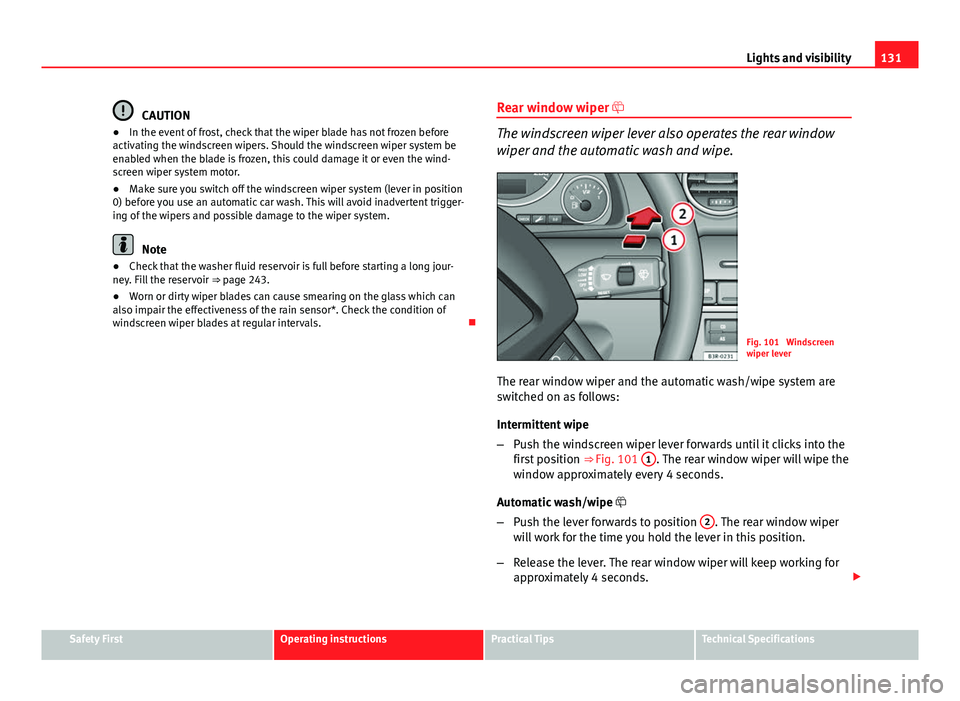
Fig. 101 Windscreen
wiper lever
The rear window wiper and the automatic wash/wipe system are
switched on as follows:
Intermittent wipe
– Push the windscreen wiper lever forwards until it clicks into the
first position ⇒ Fig. 101 1
. The rear window wiper will wipe the
window approximately every 4 seconds.
Automatic wash/wipe
– Push the lever forwards to position 2
. The rear window wiper
will work for the time you hold the lever in this position.
– Release the lever. The rear window wiper will keep working for
approximately 4 seconds.
Safety FirstOperating instructionsPractical TipsTechnical Specifications
Page 135 of 327

133
Lights and visibility
Rear vision mirrors
Interior mirror with manual anti-dazzle setting
Normal setting
– Point the lever at the bottom of the mirror forwards.
Anti-dazzle setting for the interior mirror
– Position the small lever of the lower edge of the mirror to face
towards the rear.
Interior mirror with automatic anti-dazzle adjustment*
The automatic anti-dazzle function can be switched on and
off as desired.
Fig. 103 Interior mirror
with anti-dazzle setting:
Indicator lamp and on/off
switch Switching off the anti-dazzle function
–
Press button A
⇒ Fig. 103. Control lamp B goes off.
Switching on the anti-dazzle function
– Press button A
⇒ Fig. 103. Indicator lamp B turns on.
Anti-dazzle function
The anti-dazzle function is activated every time the ignition is switched on.
The green warning lamp lights up in the rear vision mirror housing.
When the anti-dazzle function is enabled, the interior rear vision mirror will
darken automatically according to the amount of light it receives. The anti-
dazzle function is disabled if:
● the interior lighting is switched on
● reverse gear is engaged
Sensors for automatic headlights*
When the light switch is set to the AUTO position, the dipped beam head-
lights are switched on and off automatically according to the ambient light
level with the aid of the sensors located in the interior mirror ⇒ page 118.
WARNING
Electrolyte fluid can leak from a broken mirror. This could cause irritation
to the skin, eyes and respiratory organs. If you come into contact with
this liquid, it must be rinsed with large quantities of water. Seek medical
assistance if needed!
CAUTION
Electrolyte fluid leaking from a broken mirror can cause damage to plastic
surfaces. Use a sponge or similar to remove the fluid as soon as possible.
Safety FirstOperating instructionsPractical TipsTechnical Specifications
Page 137 of 327

135
Lights and visibility
CAUTION
● Rear view convex or aspheric* mirrors increase the field of vision, al-
though objects appear smaller and further away in the mirrors. Therefore,
you should not rely on these mirrors for judging the distance of vehicles be-
hind.
● If one of the mirror housings is knocked out of position (e.g. when park-
ing), the mirrors must first be fully retracted with the electric control. Do not
readjust the mirror housing by hand, as this will interfere with the mirror ad-
juster function.
Note
If the electrical adjustment ever fails to operate, the mirrors can be adjusted
by hand by lightly pressing the edge of the mirror glass.
Safety FirstOperating instructionsPractical TipsTechnical Specifications
Page 139 of 327

137
Seats and storage
WARNING
● The height of the driver seat must not be adjusted while driving. Fail-
ure to do so could result in an accident.
● Be careful when adjusting the seat height. Injuries can be caused if
the seat height is adjusted without due care and attention.
Adjusting the backrest angle
– Lean forwards to take your weight off the backrest.
– Turn the adjuster wheel 3
⇒ Fig. 105 to set the angle of the
backrest as required.
WARNING
The front seat backrests must not be reclined for driving. Otherwise, seat
belts and the airbag system might not protect as they should, with the
subsequent danger of injury.
Adjusting lumbar support*
– Do not exert any pressure on the backrest and turn adjuster
wheel 4 ⇒ Fig. 105 to adjust lumbar support.
As you make the adjustments, the curvature of the cushioned area of the
lumbar region becomes more or less acute. In this way, it adapts to the nat-
ural curvature of the spine.
Safety FirstOperating instructionsPractical TipsTechnical Specifications
Page 141 of 327

139
Seats and storage
Controls Seat adjustment
Backrest adjustment
Lumbar support*
WARNING
● The electrical seat adjustment also works when the ignition is off or
when the key is not in the ignition. To avoid accidental injuries, never
leave children unattended in the vehicle.
● For safety reasons, the seat must only be adjusted when the vehicle
is at a standstill. Failure to do so could result in an accident.
● Be careful when adjusting the seat height. Injuries can be caused if
the seat height is adjusted without due care and attention.
Adjusting the backrest angle
Fig. 108 Front seat:
Backrest adjuster switch
A
BC
–
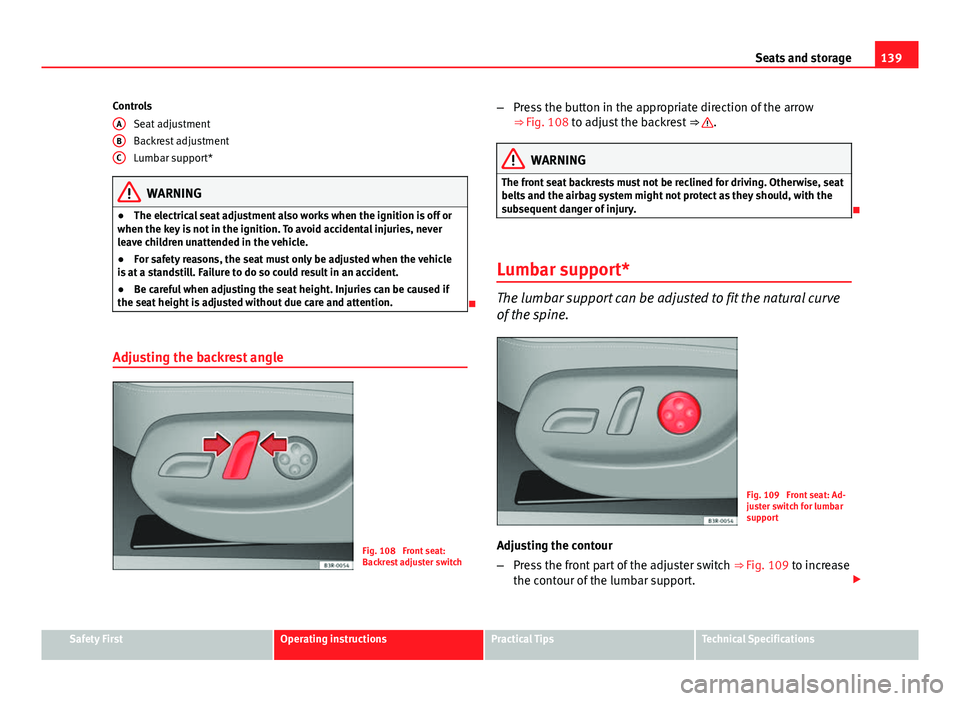
Press the button in the appropriate direction of the arrow
⇒ Fig. 108 to adjust the backrest ⇒ .
WARNING
The front seat backrests must not be reclined for driving. Otherwise, seat
belts and the airbag system might not protect as they should, with the
subsequent danger of injury.
Lumbar support*
The lumbar support can be adjusted to fit the natural curve
of the spine.
Fig. 109 Front seat: Ad-
juster switch for lumbar
support
Adjusting the contour
– Press the front part of the adjuster switch ⇒
Fig. 109 to increase
the contour of the lumbar support.
Safety FirstOperating instructionsPractical TipsTechnical Specifications
Page 143 of 327

141
Seats and storage
system when the vehicle is being driven temporarily by a different driver
whose settings do not need to be stored in the memory.
Note
You can also use the remote control to call up the stored settings
⇒ page 142.
Storing settings
The STOP button must be in its down position (pressed in) before
you can store the desired settings.
– Adjust the driver seat as required ⇒ page 138.
– Adjust both exterior mirrors ⇒ page 134.
– Press and hold the MEMO
button. At the same time, press one
of the memory buttons for at least a second.
– Release both buttons. The setting is now stored on the selected
memory button.
Any new setting selected automatically cancels the existing setting stored
on the memory button. It is best to begin with memory button No. 1 for the
first driver and then assign the other memory buttons to each subsequent
driver.
The seat and mirror positions are stored when the vehicle is locked with the
remote control and are assigned to the remote control key. The exterior mir-
rors adjust automatically to the previous position when you unlock the vehi-
cle; the driver seat adjusts automatically when you open the driver door.
However, this does not delete the settings stored in memory buttons 1 to 4.
These settings can be enabled at any time. Activating settings
Stored settings can be recalled using either the memory but-
tons or the remote control (remote control key).
Using the memory buttons
– If the driver door is open, press the desired memory button
briefly.
– If the driver door is closed, press and hold down the appropri-
ate memory button until the seat and exterior mirrors reach
their programmed positions.
Using the remote control
– Unlock the vehicle using the remote control and open the driver
door within the next ten minutes.
The seat adjustment will have to be called up using the memory buttons if
the driver door is not opened within 10 minutes after unlocking the vehicle
with the remote control.
WARNING
● For safety reasons, the seat must only be adjusted when the vehicle
is at a standstill. Failure to do so could result in an accident.
● In an emergency, the memory function can be stopped at any time by
pressing the STOP button or by briefly pressing any of the memory but-
tons.
Safety FirstOperating instructionsPractical TipsTechnical Specifications