technical data Seat Ibiza SC 2009 Owner's manual
[x] Cancel search | Manufacturer: SEAT, Model Year: 2009, Model line: Ibiza SC, Model: Seat Ibiza SC 2009Pages: 257, PDF Size: 6.61 MB
Page 203 of 257
If and when201
Safety First
Controls and equipment
Practical tips
Technical Data
WARNING
Loosen the wheel bolts only about one turn before raising the vehicle with
the jack, loosening the wheel bolts more than one turn can result in an acci-
dent.
Note
•Do not use the hexagonal socket in the screwdriver handle to loosen or
tighten the wheel bolts.•If the wheel bolt is very tight, you may be able to loosen it by pushing
down the end of the spanner carefully with your foot. Hold on to the vehicle
for support and take care not to slip.Raising the vehicle
In order to remove the wheel, the vehicle must be raised with
a jack.
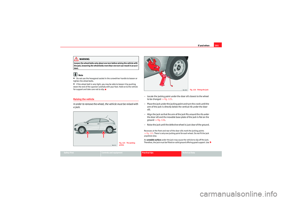
– Locate the jacking point under the door sill closest to the wheel to be changed ⇒fig. 125 .
– Place the jack under the jacking point and turn the crank until the arm of the jack is directly below the vertical rib under the door
sill.
– Align the jack so that the arm of the jack fits around the rib under the door sill and the movable base plate of the jack is flat on the
ground ⇒fig. 126 .
– Raise the jack until the defective wheel is just clear of the ground.Recesses at the front and rear of the door sills mark the jacking points
⇒ fig. 125 . There is only one jacking point for each wheel. Do not fit the jack
anywhere else.
An unstable surface under the jack may cause the vehicle to slip off the jack.
Therefore, the jack must be fitted on solid ground offering good support. Use
Fig. 125 The jacking
points
Fig. 126 Fitting the jack
IbizaSC_EN.book Seite 201 Mittwoch, 16. September 2009 12:11 12
Page 205 of 257
If and when203
Safety First
Controls and equipment
Practical tips
Technical Data
Anti-theft wheel bolts*
A special adapter is required to turn the anti-theft wheel
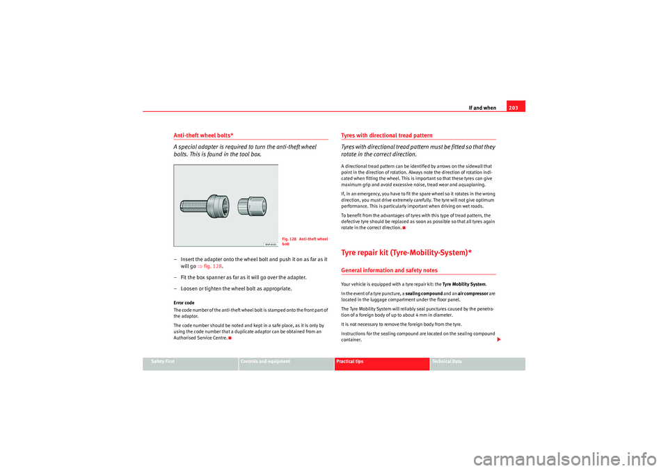
bolts. This is found in the tool box.– Insert the adapter onto the wheel bolt and push it on as far as it
will go ⇒ fig. 128.
– Fit the box spanner as far as it will go over the adapter.
– Loosen or tighten the wheel bolt as appropriate.Error code
The code number of the anti-theft wheel bolt is stamped onto the front part of
the adaptor.
The code number should be noted and kept in a safe place, as it is only by
using the code number that a duplicate adaptor can be obtained from an
Authorised Service Centre.
Tyres with directional tread pattern
Tyres with directional tread pattern must be fitted so that they
rotate in the correct direction.A directional tread pattern can be identified by arrows on the sidewall that
point in the direction of rotation. Always note the direction of rotation indi-
cated when fitting the wheel. This is important so that these tyres can give
maximum grip and avoid excessive noise, tread wear and aquaplaning.
If, in an emergency, you have to fit the spare wheel so it rotates in the wrong
direction, you must drive extremely carefully. The tyre will not give optimum
performance. This is particularly important when driving on wet roads.
To benefit from the advantages of tyres with this type of tread pattern, the
defective tyre should be replaced as soon as possible so that all tyres again
rotate in the correct direction.Tyre repair kit (Tyre-Mobility-System)*General information and safety notesYour vehicle is equipped with a tyre repair kit: the Ty re Mo bil it y Syste m.
In the event of a tyre puncture, a sealing compound and an air compressor are
located in the luggage compartment under the floor panel.
The Tyre Mobility System will reliably seal punctures caused by the penetra-
tion of a foreign body of up to about 4 mm in diameter.
It is not necessary to remove the foreign body from the tyre.
Instructions for the sealing compound are located on the sealing compound
container.
Fig. 128 Anti-theft wheel
bolt
IbizaSC_EN.book Seite 203 Mittwoch, 16. September 2009 12:11 12
Page 207 of 257
If and when205
Safety First
Controls and equipment
Practical tips
Technical Data
Tyre repair
The following sections describe the procedures for repairing
a tyre.Using the sealing compound
– The instructions on the container give detailed information on
how to use the sealing compound.
Inflating the tyre.
– Remove the air compressor and hose from the container.
– Screw the retaining nut onto the valve.
– Plug the compressor cable into a 12 volt power point.
– Turn on compressor and monitor the pressure shown on the pres- sure gauge.
Completing the repair
– Remove the compressor hose from the valve.
– Fit the valve cap.
– Unplug the compressor from the socket.
– Return all tools to their proper storing location.
NoteThe compressor should never be allowed to run for longer than 6 minutes.
FusesChanging a fuse
Blown fuses must be replacedFuse cover
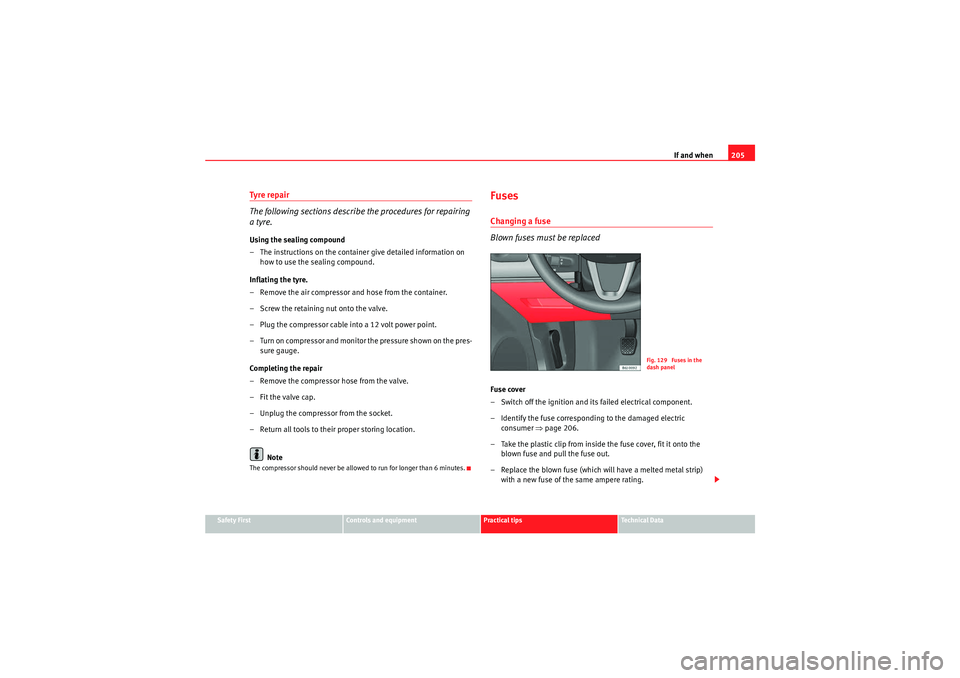
– Switch off the ignition and its failed electrical component.
– Identify the fuse corresponding to the damaged electric consumer ⇒page 206.
– Take the plastic clip from inside the fuse cover, fit it onto the blown fuse and pull the fuse out.
– Replace the blown fuse (which will have a melted metal strip) with a new fuse of the same ampere rating.
Fig. 129 Fuses in the
dash panel
IbizaSC_EN.book Seite 205 Mittwoch, 16. September 2009 12:11 12
Page 209 of 257
If and when207
Safety First
Controls and equipment
Practical tips
Technical Data
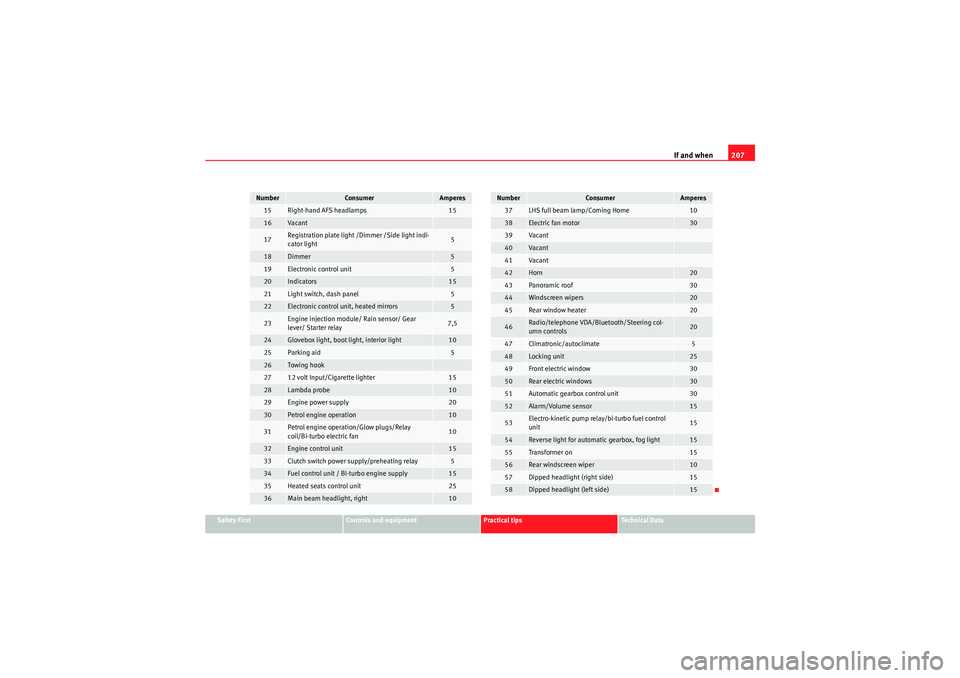
15
Right-hand AFS headlamps
15
16
Va can t
17
Registration plate light /Dimmer /Side light indi-
cator light
5
18
Dimmer
5
19
Electronic control unit
5
20
Indicators
15
21
Light switch, dash panel
5
22
Electronic control unit, heated mirrors
5
23
Engine injection module/ Rain sensor/ Gear
lever/ Starter relay
7,5
24
Glovebox light, boot light, interior light
10
25
Parking aid
5
26
Towing hook
27
12 volt Input/Cigarette lighter
15
28
Lambda probe
10
29
Engine power supply
20
30
Petrol engine operation
10
31
Petrol engine operation/Glow plugs/Relay
coil/Bi-turbo electric fan
10
32
Engine control unit
15
33
Clutch switch power supply/preheating relay
5
34
Fuel control unit / Bi-turbo engine supply
15
35
Heated seats control unit
25
36
Main beam headlight, right
10
Number
Consumer
Amperes
37
LHS full beam lamp/Coming Home
10
38
Electric fan motor
30
39
Va can t
40
Va can t
41
Va can t
42
Horn
20
43
Panoramic roof
30
44
Windscreen wipers
20
45
Rear window heater
20
46
Radio/telephone VDA/Bluetooth/Steering col-
umn controls
20
47
Climatronic/autoclimate
5
48
Locking unit
25
49
Front electric window
30
50
Rear electric windows
30
51
Automatic gearbox control unit
30
52
Alarm/Volume sensor
15
53
Electro-kinetic pump relay/bi-turbo fuel control
unit
15
54
Reverse light for automatic gearbox, fog light
15
55
Transformer on
15
56
Rear windscreen wiper
10
57
Dipped headlight (right side)
15
58
Dipped headlight (left side)
15
Number
Consumer
Amperes
IbizaSC_EN.book Seite 207 Mittwoch, 16. September 2009 12:11 12
Page 211 of 257
If and when209
Safety First
Controls and equipment
Practical tips
Technical Data
Bulb changeGeneral notesBefore changing any bulb, first turn off the failed component.
Do not touch the bulb glass. Fingerprints vaporise in the heat, causing a
reduction in the bulb life and condensation on the mirror surface, thus
reducing efficiency.
A bulb should only be replaced by one of the sam e type. The type is inscribed
on the bulb, either on the glass part or on the base.
It is highly recommended to keep a box of spare bulbs in the vehicle. At the
very least, the following spare bulbs, which are essential for road safety,
should be kept in the vehicle.
Double headlamps
Dipped beam - H7 Long Life
Main beam - H7
Position - 2 x W5W Long Life
Indicator - PY21W
Single headlamp
Dipped/Main - H4 Long Life
Position - W5W Long Life
Indicator - PY 21W
Xenon headlights
12)/ self-adjusting*
Dipped and full beam - D1S
13)
Position - W5W Blue Long Life DRL (day light) - P21W Super Long Life
Indicators - PY21W
Fog lights
Fog light/cornering - H11
Rear lights
Fog light - P21W
Reverse gear - R10W
Stop/position - P21 /5W Long Life
Indicator - PY21W
Side indicator
Side indicator - W5W
Registration plate light
Registration plate light - W5W Long Life
Note
•Depending on weather conditions (cold or wet), the front lights, the fog
lights, the rear lights and the indicators may be temporarily misted. This has
no influence on the useful life of the lighting system. By switching on the
lights, the area through which the beam of light is projected will quickly be
demisted. However, the edges may continue to be misted.•Please check at regular intervals that all lighting (especially the exterior
lighting) on your vehicle is functioning pr operly. This is not only in the interest
of your own safety, but also that of all other road users.•D u e t o t h e d i f f i c u l t y i n a cc e s s i n g s o m e o f t h e b u l b s , a n y r e p l a c e m e n t w o r k
should be done by a SEAT dealer. However, there is a description below as to
how to change these bulbs, except for the fog lights.
12)On this type of headlight, the bulb changes must be made by the SEAT dealer, given
that complex elements must be removed from the vehicle and a reset must be made
on the automatic control system incorporated.
13)The Xenon bulbs discharge 2.5 times the light flux and have an average lifespan of 5
times more than that of halogen bulbs, this means that, except due to unusual circum-
stances, there is no need to change the bulbs for the whole life of the vehicle.
IbizaSC_EN.book Seite 209 Mittwoch, 16. September 2009 12:11 12
Page 213 of 257
If and when211
Safety First
Controls and equipment
Practical tips
Technical Data
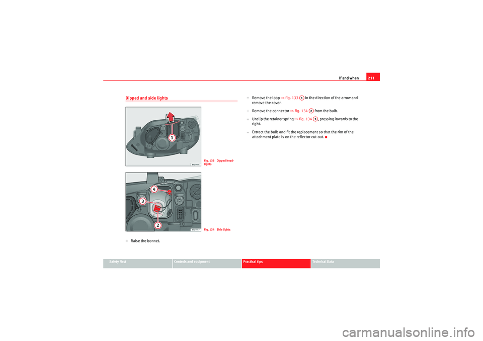
Dipped and side lights– Raise the bonnet. – Remove the loop
⇒fig. 133 in the direction of the arrow and
remove the cover.
– Remove the connector ⇒fig. 134 from the bulb.
– Unclip the retainer spring ⇒fig. 134 , pressing inwards to the
right.
– Extract the bulb and fit the replacement so that the rim of the attachment plate is on the reflector cut-out.
Fig. 133 Dipped head-
lightsFig. 134 Side lights
A1
A2A3
IbizaSC_EN.book Seite 211 Mittwoch, 16. September 2009 12:11 12
Page 215 of 257

If and when213
Safety First
Controls and equipment
Practical tips
Technical Data
Indicator lamps– Raise the bonnet.
– Rotate the bulb holder ⇒fig. 138 to the left and pull.
– Remove the bulb by pressing on the lamp holder and rotating at the same time to the left.
– Installation is done in the reverse order.
Dipped/main beam– Raise the bonnet.
Fig. 138 Single indicator
lamp
AA
Fig. 139 Dipped beam /
main beam, single lightFig. 140 Dipped beam /
main beam, single light
IbizaSC_EN.book Seite 213 Mittwoch, 16. September 2009 12:11 12
Page 217 of 257
If and when215
Safety First
Controls and equipment
Practical tips
Technical Data
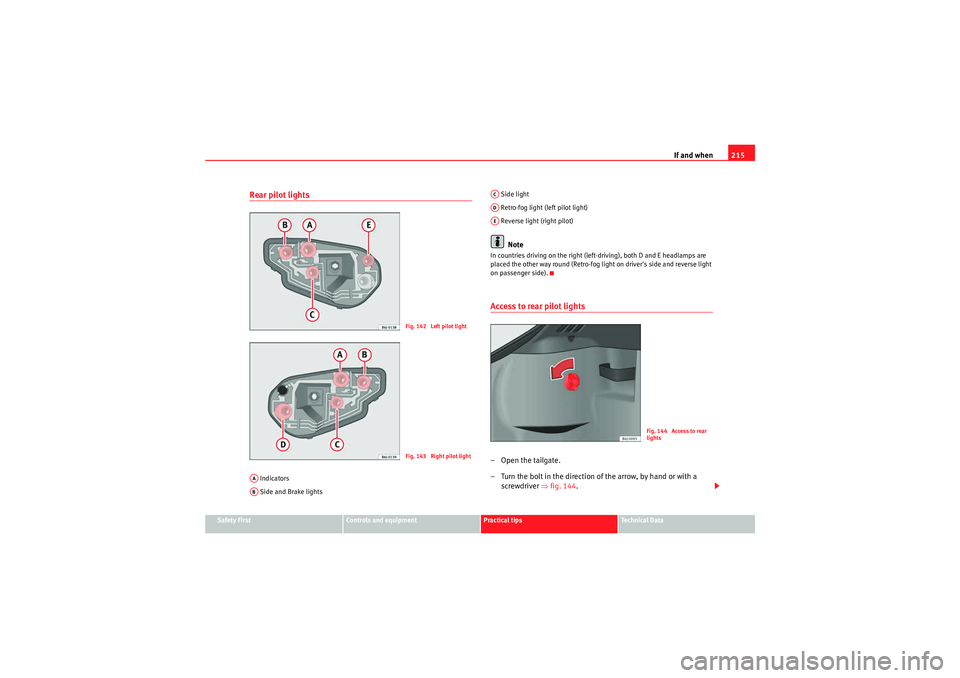
Rear pilot lights Indicators
Side and Brake lights Side light
Retro-fog light (left pilot light)
Reverse light (right pilot)
Note
In countries driving on the right (left-driving), both D and E headlamps are
placed the other way round (Retro-fog light on driver's side and reverse light
on passenger side).Access to rear pilot lights–Open the tailgate.
– Turn the bolt in the direction of the arrow, by hand or with a
screwdriver ⇒fig. 144 .
Fig. 142 Left pilot lightFig. 143 Right pilot light
AAAB
ACADAE
Fig. 144 Access to rear
lights
IbizaSC_EN.book Seite 215 Mittwoch, 16. September 2009 12:11 12
Page 219 of 257
If and when217
Safety First
Controls and equipment
Practical tips
Technical Data
– Insert the lamp holder in the indicator guide until it clicks into
place.
– First fit the indicator in the opening in the chassis, fastening the tabs ⇒page 216, fig. 147 , and then fit in the lamp as shown
by the arrow ⇒page 216, fig. 147 .Number plate light– Insert the flat part of a screwdriver into the special slot and
remove the bulb.
– Remove the lamp holder, by turning it until it is free.
– Change the bulb.
– Replace the lamp holder, by turning it until it fits fully.
– Fit the light into the space and press until you hear a “click”.
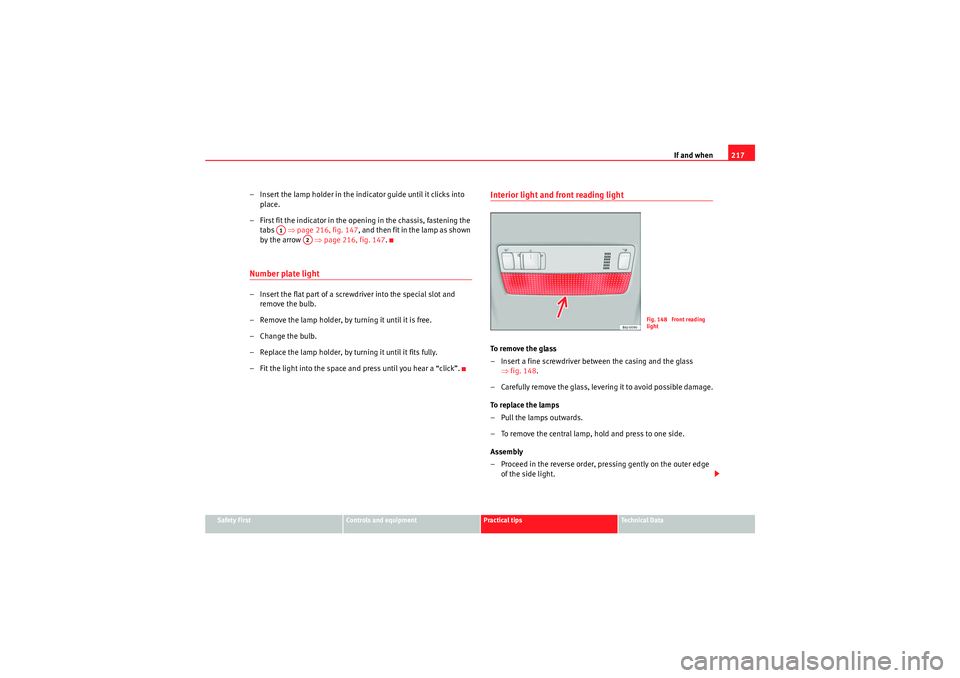
Interior light and front reading light To r e m o v e t h e g l a s s
– Insert a fine screwdriver between the casing and the glass ⇒fig. 148 .
– Carefully remove the glass, levering it to avoid possible damage.
To replace the lamps
– Pull the lamps outwards.
– To remove the central lamp, hold and press to one side.
Assembly
– Proceed in the reverse order, pressing gently on the outer edge of the side light.
A1
A2
Fig. 148 Front reading
light
IbizaSC_EN.book Seite 217 Mittwoch, 16. September 2009 12:11 12
Page 221 of 257
If and when219
Safety First
Controls and equipment
Practical tips
Technical Data
Jump leads
Jump leads must comply with the standard
DIN 72553 (see manufacturer's
documentation). The wire cross section must be at least 25 mm
2 for petrol
engines and at least 35 mm
2 for diesel engines.
Note
•The vehicles must not touch each other, otherwise electricity could flow as
soon as the positive terminals are connected.•The discharged battery must be properly connected to the vehicle elec-
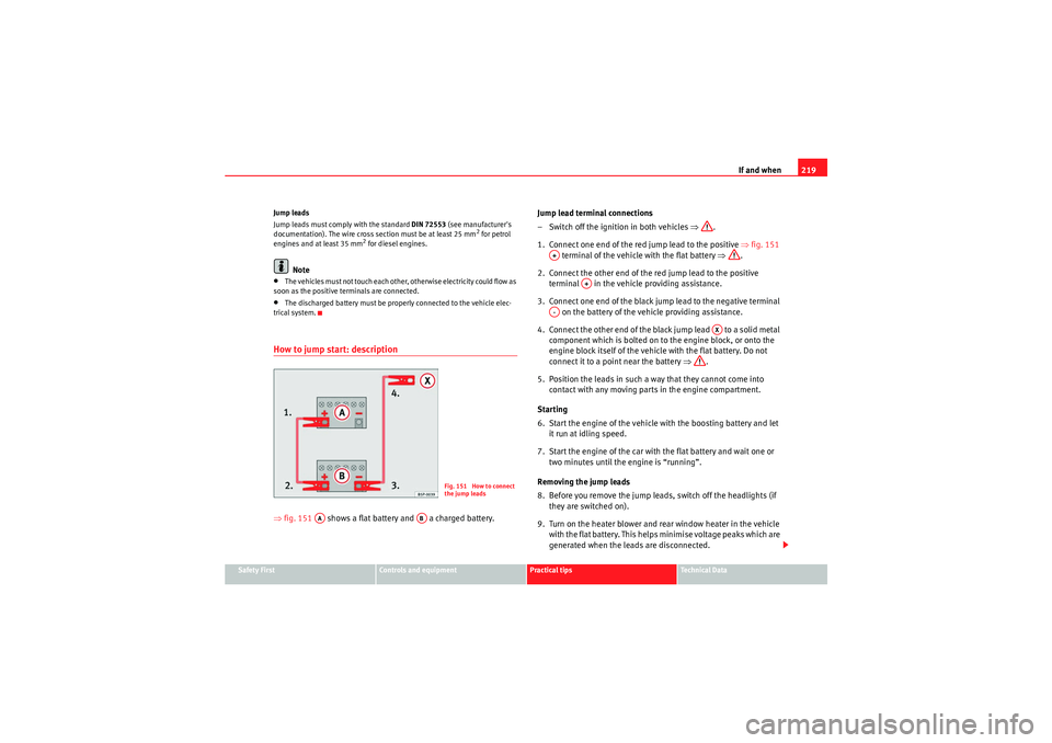
trical system.How to jump start: description⇒ fig. 151 shows a flat battery and a charged battery. Jump lead terminal connections
– Switch off the ignition in both vehicles
⇒.
1. Connect one end of the red jump lead to the positive ⇒fig. 151
terminal of the vehicle with the flat battery ⇒.
2. Connect the other end of the red jump lead to the positive terminal in the vehicle providing assistance.
3. Connect one end of the black jump lead to the negative terminal on the battery of the vehicle providing assistance.
4. Connect the other end of the black jump lead to a solid metal component which is bolted on to the engine block, or onto the
engine block itself of the vehicle with the flat battery. Do not
connect it to a point near the battery ⇒.
5. Position the leads in such a way that they cannot come into contact with any moving parts in the engine compartment.
Starting
6. Start the engine of the vehicle with the boosting battery and let it run at idling speed.
7. Start the engine of the car with the flat battery and wait one or two minutes until the engine is “running”.
Removing the jump leads
8. Before you remove the jump leads, switch off the headlights (if they are switched on).
9. Turn on the heater blower and rear window heater in the vehicle with the flat battery. This helps minimise voltage peaks which are
generated when the leads are disconnected.
Fig. 151 How to connect
the jump leads
AA
AB
A+
A+
A-
AX
IbizaSC_EN.book Seite 219 Mittwoch, 16. September 2009 12:11 12