tyre pressure Seat Ibiza ST 2016 Owner's manual
[x] Cancel search | Manufacturer: SEAT, Model Year: 2016, Model line: Ibiza ST, Model: Seat Ibiza ST 2016Pages: 252, PDF Size: 5.56 MB
Page 26 of 252
The essentials
Easy Connect CAR menu settin g
s (Set
up)Fig. 35
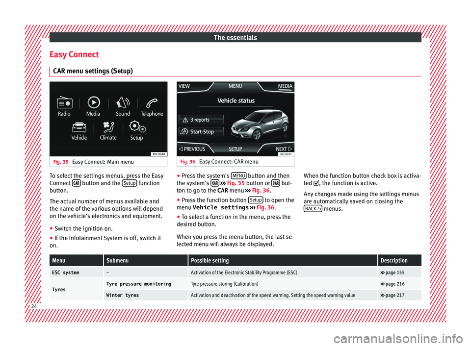
Easy Connect: Main menu Fig. 36
Easy Connect: CAR menu To select the settings menus, press the Easy
C
onnect
button and the
Set
up function
b utt
on.
The act ual
number of menus available and
the name of the various options will depend
on the vehicle’s electronics and equipment.
● Switch the ignition on.
● If the Infotainment System is off, switch it
on. ●
Press the system's MENU button and then
the sy s
tem's
› ››
Fig. 35
button or but-
t on t
o go t
o the CAR menu ››› Fig. 36.
● Press the function button Setup to open the
menu Vehicle settings › ›
›
Fig. 36
.
● To select a function in the menu, press the
desired b
utton.
When you press the menu button, the last se-
lected menu will always be displayed. When the function button check box is activa-
ted , the f
unction is active.
Any changes made using the settings menus
are automatically saved on closing the BACK menus.
MenuSubmenuPossible settingDescription
ESC system–Activation of the Electronic Stability Programme (ESC)›››
page 155
TyresTyre pressure monitoringTyre pressure storing (Calibration)››› page 216
Winter tyresActivation and deactivation of the speed warning. Setting the speed warning value››› page 217 24
Page 38 of 252
The essentials
Front brake pads worn.
›››
page
155
it lights up:
Fault in the ESC, or dis-
connection caused by the system.
flashes: ESC or ASR activated.
ASR manually deactivated.
Or else
: ESC in Sport mode.
ABS faulty or does not work.
Front fog lights switched on.›››
page
21
Rear fog light switched on.›››
page
21
lights up or flashes:
fault in the
emission control system.››› page
171
it lights up:
pre-heating of diesel
engine.
››› page
171
flashes: fault in the diesel engine
management.
fault in the petrol engine manage-
ment.›››
page
171
lights up or flashes:
fault in the
steering system.››› page
148
Tyre pressure too low, or fault in
the tyre pressure monitoring sys-
tem.›››
page
216
Fuel tank almost empty.›››
page
100
Fault in airbag system and seat
belt tensioners.›››
page
66 Other warning lamps
Left or right turn signal.›››
page
22
Hazard warning lights on.››› page
123
Trailer turn signals›››
page
186
it lights up:
Press the foot brake!
flashes: the selector lever locking
button has not engaged.››› page
161
it lights up:
cruise control activated
or speed limiter switched on and
active.
››› page
34
flashes: the speed set by the
speed limiter has been exceeded.
Main beam on or flasher on.›››
page
22 On the instrument panel display
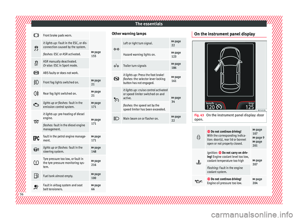
Fig. 43
On the instrument panel display: door
open.
Do not continue driving!
With the corresponding indica-
tion: door(s), rear lid or bonnet
open or not properly closed.››› page
107
››› page 9
››› page
201
Ignition: Do not carry on driv-
ing! Engine coolant level too low,
coolant temperature too high
››› page
207
Flashing: Fault in the engine
coolant system.
Do not continue driving!
Engine oil pressure too low.››› page
204 36
Page 48 of 252
The essentials
Repairing a tyre with the anti-punc-
t ur
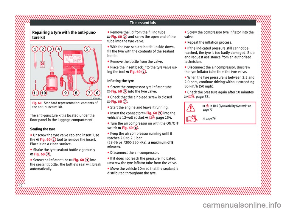
e k it Fig. 60
Standard representation: contents of
the anti-p u
nct ur
e kit. The anti-puncture kit is located under the
floor p
anel
in the lug g
age compartment.
Sealing the tyre
● Unscrew the tyre valve cap and insert. Use
the ››› Fig. 60
1 tool to remove the insert.
Pl ac
e it on a c
lean surface.
● Shake the tyre sealant bottle vigorously
››› Fig. 60
10 .
● Screw the inflator tube ››
›
Fig. 60
3 into
the se al
ant bottl
e. The bottle's seal will break
automatically. ●
Remove the lid fr
om the filling tube
››› Fig. 60 3 and screw the open end of the
t ube int
o the ty r
e valve.
● With the tyre sealant bottle upside down,
fill the ty
re with the contents of the sealant
bottle.
● Remove the bottle from the valve.
● Place the insert back into the tyre valve us-
ing the tool
››› Fig. 60 1 .
Infl atin
g the ty r
e
● Screw the compressor tyre inflator tube
››› Fig. 60
5 into the tyre valve.
● Check that the air bleed screw is closed
› ›
›
Fig. 60
7 .
● Start the engine and leave it running.
● Insert the connector ››
›
Fig. 60
9 into the
v ehic
le's
12-volt socket ›››
page 134.
● Turn the air compressor on with the ON/OFF
switch ›
›› Fig. 60 8 .
● Keep the air compressor running until it
r e
ac he
s 2.0 to 2.5 bar
(29-36 psi/200-250 kPa). a maximum of 8
minutes.
● Disconnect the air compressor.
● If it does not reach the pressure indicated,
unsc
rew the tyre inflator tube from the valve.
● Move the vehicle 10m so that the sealant is
distrib ut
ed throughout the tyre. ●
Screw the c ompr
essor tyre inflator into the
valve.
● Repeat the inflation process.
● If the indicated pressure still cannot be
reached, the ty
re is too badly damaged. Stop
and request assistance from an authorised
technician.
● Disconnect the air compressor. Unscrew
the tyre inflat
or tube from the tyre valve.
● When the tyre pressure is between 2.5 and
2.0 bars, continue driv
ing without exceeding
80 km/h (50 mph).
● Check the pressure again after 10 minutes
››› p
age 78.
››› in TMS (Tyre Mobility System)* on
page 77
››› page 76 46
Page 52 of 252
The essentials
Subsequent work ●
Alloy wheels: replac e the wheel bolt caps.
● Plate wheels: replac
e the wheel hubcap.
● Return all tools to their proper storing loca-
tion.
● If the replaced wheel does not fit in the
spare wheel
housing, store it safely in the
luggage compartment ›››
page 135.
● Check the tyre pressure of the newly moun-
ted tyre a
s soon as possible.
● In vehicles fitted with a tyre pressure indi-
cator , a
djust the pressure and store it in
memory ›››
page 216.
● Have the tightening torque of the wheel
bolts chec
ked as soon as possible with a tor-
que wrench (it should be 120 Nm). Mean-
while, drive carefully.
● Have the flat tyre replaced as quickly as
possib
le.
Snow chains Use Snow chains should only be used on the
fr
on
t wheel
s.
● Check that they are correctly seated after
driving for a f
ew yards; correct the position if necessary, in accordance with the manufac-
turer's fittin
g instructions.
● Keep your speed below 50 km/h (30 mph).
● If there is a danger of being trapped de-
spite hav
ing mounted the chains, it is best to
disable the driving wheels (ASR) in the ESC
››› page 155.
Snow chains will improve braking ability as
well as traction in winter conditions.
For technical reasons snow chains may only
be used with the following wheel rim/tyre
combination.
175/70R14
185/60R15Chains with links not exceeding 15 mm
(including the chain closure)
215/45R16Chains with links not exceeding 9 mm
(including the chain closure)
215/40R17Chains with links not exceeding 7 mm
(including the chain closure) Remove wheel covers and any integral trim
rin
g bef
ore fittin
g snow chains.
Remove the chains when roads are free of
snow. Driving characteristics worsen, and the
wheels become damaged quickly and may
even be rendered unusable. WARNING
Snow chains should be correctly tightened in
accor d
ance with the manufacturer's instruc- tions. This will prevent the chains coming in-
to cont
act
with the wheel housing.50
Page 58 of 252
Safety
Safety
Saf e driv
ing
Saf
ety first! This chapter contains important information,
tips, sug
g
estions and warnings that you
should read and consider for both your own
safety and for your passengers' safety. WARNING
● This m anua
l contains important informa-
tion about the operation of the vehicle, both
for the driver and the passengers. The other
sections of the on-board documentation also
contain further information that you should
be aware of for your own safety and for the
safety of your passengers.
● Ensure that the on-board documentation is
kept in the v
ehicle at all times. This is espe-
cially important when lending or selling the
vehicle to another person. Advice about driving
B ef or
e settin
g offFor your own safety and the safety of your
p
a
ssen
gers, always note the following points
before every trip: –
Make sur
e that the vehicle's lights and turn
signals are working properly.
– Check tyre pressure.
– Ensure that all windows provide a clear and
good view of
the surroundings.
– Ensure that all luggage is correctly secured
››› p
age 135.
– Make sure that no objects can interfere
with the pedals.
– Adju
st front seat, head restraint and mir-
rors pr
operly according to your size.
– Ensure that the passenger in the central
rear seat
always has the head restraint in
the correct position for use.
– Instruct passengers to adjust the head re-
straints ac
cording to their height.
– Protect children with appropriate child
seats and properly
applied seat belts
››› page 72.
– Assume the correct sitting position. Instruct
your pas
sengers also to assume a proper
sitting position. ››› page 57.
– Fasten your seat belt securely. Instruct your
passen
gers also to fasten their seat belts
properly. ››› page 61. What affects driving safety? As a driver, you are responsible for yourself
and your p
a
ssengers. When your concentra-
tion or driving safety is affected by any cir-
cumstance, you endanger yourself as well as
others on the road ››› , for this reason:
– Always pay attention to traffic and do not
get di s
tracted by passengers or telephone
calls.
– Never drive when your driving ability is im-
paired (e.g. b
y medication, alcohol, drugs).
– Observe traffic laws and speed limits.
– Always reduce your speed as appropriate
for ro a
d, traffic and weather conditions.
– When travelling long distances, take
breaks
regularly - at least every two hours.
– If possible, avoid driving when you are tired
or stres
sed. WARNING
When driving safety is impaired during a trip,
the risk of injur
y and accidents increases. Safety equipment
Never put your safety or the safety of your
p
a
ssen
gers in danger. In the event of an acci-
dent, the safety equipment may reduce the
56
Page 78 of 252
Emergencies
●
Never st ar
t the engine when the vehicle is
on the jack. Risk of accident.
● If work is to be carried out underneath the
vehicle, thi
s must be secured by suitable
means. Otherwise, there is a risk of injury. Note
The jack does not generally require any main-
t enanc e. If
required, it should be greased us-
ing universal type grease. Spare wheel (temporary spare
wheel)*
The temporary spare wheel is stored under
the floor p
anel
in the lug g
age compartment
and is attached by a thumbnut.
How to use the temporary spare wheel
If you ever have a punctured tyre or loss of
pressure, the temporary spare wheel is only
intended for temporary use until you reach a
workshop. Change it for a duty wheel as soon
as possible.
Please note the following restrictions when
using the temporary spare wheel. This tem-
porary spare wheel has been specially de-
signed for your vehicle, thus, it cannot be
changed with the temporary spare wheel
from another vehicle. No other type of tyre (normal summer or win-
ter tyre) m
ay be fitted on the compact tempo-
rary spare wheel rim.
Snow chains
For technical reasons, snow chains must not
be used on the temporary spare wheel.
If you have a puncture on one of the front
wheels when using snow chains, fit the tem-
porary spare wheel in place of one of the rear
wheels. Fit the snow chains on the rear wheel
that you have removed and replace the punc-
tured front wheel with this wheel.
Extraction of the spare wheel in vehicles
with SEAT SOUND 6 speakers (with subwoof-
er)*
● Disassemble the subwoofer's floor p
anel
(carpet) as follows:
● Pull the carpet upwards to remove it.
● Disconnect the subwoofer's s
peaker cable.
● Turn the securing wheel anti-clockwise.
● Remove the subwoofer s
peaker and the
spare wheel.
● When replacing the spare wheel, place the
subwoofer s
peaker in the direction indicated
by the arrow and with the word “FRONT” fac-
ing forward.
● Reconnect the speaker cable and firmly ro-
tate the sec urin
g wheel clockwise so that the subwoofer syst
em and wheel
are firmly in
place. WARNING
● After fittin g the t
emporary spare wheel,
check the tyre pressures as soon as possible.
Failure to do so may cause an accident. The
tyre pressures are listed on the inside of the
fuel tank flap.
● Do not drive at over 80 km/h (50 mph)
when the temporary
spare wheel is fitted on
the vehicle: risk of accident!
● Avoid heavy acceleration, hard braking and
fast
cornering: risk of accident!
● Never use more than one temporary spare
wheel at the same time, ri
sk of accident.
● No other type of tyre (normal summer or
winter tyr
e) may be fitted on the compact
temporary spare wheel rim. Tyre repair
TM S (T
y
re Mobility System)* Read the additional information carefully
› ›
›
p
age 46
The Anti-puncture kit* (Tyre Mobility System)
will reliably seal punctures caused by the
penetration of a foreign body of up to about
4 mm in diameter. Do not remove foreign ob-
jects, e.g. screws or nails, from the tyre.
76
Page 79 of 252
Self-help
After inserting the sealant residue in the tyre,
y ou mu
st
again check the tyre pressure about
10 minutes after starting the engine.
You should only use the tyre mobility set if
the vehicle is parked in a safe place, you are
familiar with the procedure and you have the
necessary tyre mobility set! Otherwise, you
should seek professional assistance.
Do not use the tyre sealant in the following
cases:
● If the wheel rim has been damaged.
● In outside temperatures below -20 °C
(-4 °F).
● In the event of cuts or perforations in the
tyre gre
ater than 4 mm.
● If you have been driving with very low pres-
sure or a comp
letely flat tyre.
● If the sealant bottle has passed its use by
date. WARNING
Using the tyre mobility system can be dan-
gerou s, e
specially when filling the tyre at the
roadside. Please observe the following rules
to minimise the risk of injury:
● Stop the vehicle safely as soon as possible.
Park it at
a safe distance from surrounding
traffic to fill the tyre.
● Ensure the ground on which you park is flat
and solid. ●
All p
assengers and particularly children
must keep a safe distance from the work area.
● Turn on the hazard warning lights to warn
other road u
sers.
● Use the tyre mobility system only if you are
familiar w
ith the necessary procedures. Oth-
erwise, you should seek professional assis-
tance.
● The tyre mobility set is intended for tempo-
rary emer
gency use only until you can reach
the nearest specialised workshop.
● Replace the repaired tyre with the tyre mo-
bility set
as soon as possible.
● The sealant is a health hazard and must be
cleaned immedi
ately if it comes into contact
with the skin.
● Always keep the tyre mobility set out of the
reach of
small children.
● Never use a jack, even if it has been ap-
proved f
or your vehicle.
● Always stop the engine, apply the hand-
brake lev
er firmly and engage gear if using a
manual gearbox, in order to reduce the risk of
vehicle involuntary movement. WARNING
A tyre filled with sealant does not have the
same perf orm
ance properties as a conven-
tional tyre.
● Never drive faster than 80 km/h (50 mph).
● Avoid heavy acceleration, hard braking and
fast
cornering. ●
Drive for on ly
10 minutes at a maximum
speed of 80 km/h (50 mph) and then check
the tyre. For the sake of the environment
Dispose of used or expired sealant observing
an y le
gal requirements. Note
● A new bottle of se a
lant can be purchased at
SEAT dealerships.
● Take into account the separate instruction
manual of
the tyre mobility set* manufactur-
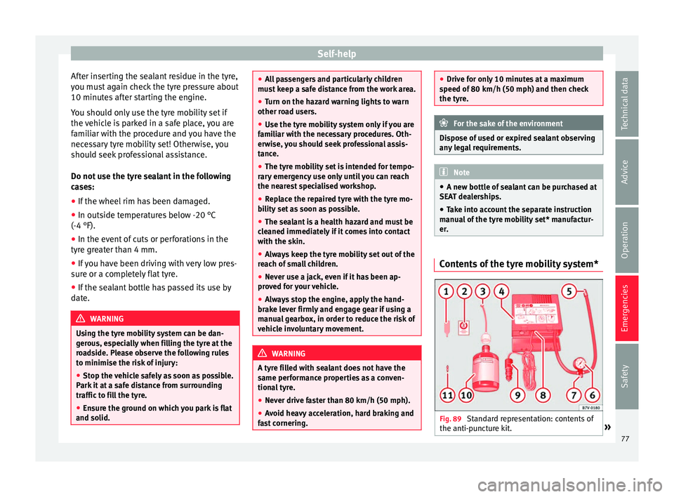
er. Contents of the tyre mobility system*
Fig. 89
Standard representation: contents of
the anti-p u
nct ur
e kit. » 77
Technical data
Advice
Operation
Emergencies
Safety
Page 80 of 252
Emergencies
The anti-puncture kit is located underneath
the floor c o
verin
g in the luggage compart-
ment. It includes the following components
››› Fig. 89:
Tyre valve remover
Sticker indicating maximum speed “max.
80 km/h” or “max. 50 mph”
Filler tube with cap
Air compressor
Tube for inflating tyres
Warning provided by tyre pressure moni-
toring system (it can also be integrated in
the compressor).
Air bleed screw (in its place, the compres-
sor may have a button).
ON/OFF switch
12 volt connector
Bottle of sealant
Spare tyre valve
The valve insert remover 1 has a gap at the
lo w
er end f or a
valve insert. The valve insert
can only be screwed or unscrewed in this
way. This also applies to its replacement part 11 .
WARNING
When inflating the wheel, the air compressor
and the inflator t ube m
ay become hot.
● Protect hands and skin from hot parts. 1
2
3
4
5
6
7
8
9
10
11 ●
Do not pl ac
e the hot flexible inflator tube or
hot air compressor on flammable material.
● Allow them to cool before storing the de-
vice.
● If it
is not possible to inflate the tyre to at
leas
t 2.0 bars (29 psi / 200 kPa), the tyre is
too badly damaged. The sealant is not in a
good condition to seal the tyre. Do not con-
tinue driving. Seek specialist assistance. CAUTION
Switch off the air compressor after a maxi-
mum of 8 operation a
l minutes to avoid over-
heating! Before switching on the air compres-
sor again, let it cool for several minutes. Check after 10 minutes of driving
Screw in the inflator tube
››
›
Fig. 89
5 again
and c hec
k the pr
essure on the gauge 6 .
1.3 b ar (19 p
si / 130 kP
a) and lower:
● Stop the vehicle! The tyre cannot
be sealed
sufficiently with the tyre mobility set.
● You should obtain professional assistance
››› .
1.4 b ar (20 p
si / 140 kP
a) and higher:
● Set the tyre pressure to the correct value
again. ●
Carefu
lly resume your journey, without ex-
ceeding 80 km/h (50 mph), until you reach
the nearest specialised workshop and re-
place the tyre. WARNING
Driving with an unsealed tyre is dangerous
and can cau se ac
cidents and serious injury.
● Do not continue driving if the tyre pressure
is 1.3 b
ar (19 psi / 130 kPa) and lower.
● Seek specialist assistance. Changing the windscreen wiper
b
l
a de
s
Changing the windscreen and rear
window wiper blades Read the additional information carefully
› ›
›
p
age 54.
Perfect wiper blade condition is essential for
clear vision. Damaged wiper blades should
be replaced immediately.
The windscreen wiper blades are supplied as
standard with a layer of graphite. This layer is
responsible for ensuring that the wipe is si-
lent. If the graphite layer is damaged, the
noise of the water as it is wiped across the
windscreen will be louder.
78
Page 138 of 252
Operation
Note
● The tyre pr e
ssure must be adjusted accord-
ing to the load. When necessary check the
tyre pressures on the label located on the in-
side fuel tank flap ››› page 213.
● Air circulation in the vehicle helps reduce
fogging of
the windows. Used air escapes
through ventilation slits in the side trim of
the luggage compartment. Ensure that the
ventilation slots are never covered.
● Straps for securing the load to the fasten-
ing rings* ar
e commercially available from ac-
cessory shops. Fastening rings*
3 Applies to the model: IBIZA ST
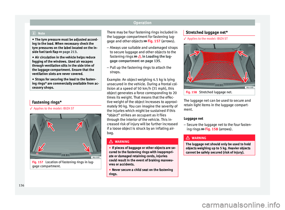
Fig. 157
Location of fastening rings in lug-
g ag
e c omp
artment. There may be four fastening rings included in
the lug
g
ag e c
ompartment for fastening lug-
gage and other objects ››› Fig. 157 (arrows).
– Always use suitable and undamaged straps
to secure lug
gage and other objects to the
fastening rings ››› in Loading the lug-
g ag
e c omp
artment on page 135.
– Pull up the fastening rings to attach the
straps.
Ex
ample: An object weighing 4.5 kg is lying
unsecured in the vehicle. During a frontal col-
lision at a speed of 50 km/h (31 mph), this
object generates a force corresponding to 20
times its weight. That means that the effec-
tive weight of the object increases to approxi-
mately 90 kg. You can imagine the severity of
the injuries which might be sustained if this
“object” strikes an occupant as it flies
through the interior of the vehicle. This in-
creased risk of injury will be further increased
if a loose object is struck by an inflating air-
bag. WARNING
● If piece s
of baggage or other objects are se-
cured to the fastening rings with inappropri-
ate or damaged retaining cords, injuries
could result in the event of braking manoeu-
vres or accidents.
● Never secure a child seat on the fastening
rings. Stretched luggage net*
3 Applies to the model: IBIZA ST
Fig. 158
Stretched luggage net. The luggage net can be used to secure and
r
et
ain light it
ems in the luggage compart-
ment.
Luggage net
– Secure the luggage net to the four fasten-
ing rings
››› Fig. 158 (arrows). WARNING
The luggage net should only be used to hold
obj ect
s weighing up to 5 kg. Heavier objects
cannot be safely secured (risk of injury). 136
Page 160 of 252
Operation
At speeds of up to approximately 80 km/h
(50 mph), it i
s ab
le to balance out differences
in the speed of the driven wheels of approxi-
mately 100 rpm/min caused by a partially
slippery road surface. It does this by braking
the wheel which has lost traction and distrib-
uting more driving force to the other driven
wheel via the differential.
To prevent the disc brake of the braking
wheel from overheating, the EDL cuts out au-
tomatically if subjected to excessive loads.
The vehicle will continue to function normally
without EDL. For this reason, the driver is not
informed that the EDL has been switched off.
The EDL will switch on again automatically
when the brake has cooled down.
Control lamp
A malfunction in the EDL is indicated by the
ABS control lamp ››› page 158. Take the
vehicle to a specialised workshop as soon as
possible. WARNING
● When accel er
ating on a slippery surface,
for example on ice and snow, press the accel-
erator carefully. Despite EDL, the driven
wheels may start to spin. This could impair
the vehicle's stability.
● Always adapt your driving style to suit road
conditions and the tr
affic situation. Do not let
the extra safety afforded by EDL tempt you in- to taking any risks when driving, this can
cause ac
c
idents. CAUTION
Modifications to the vehicle (e.g. to the en-
gine, the br ake sys
tem, running gear or any
components affecting the wheels and tyres)
could affect the efficiency of the EDL
››› page 190. Hydraulic Brake Assist (HBA)*
The function (Hydraulic Brake Assist HBA) is
on
ly
inc luded in
vehicles with ESC.
In an emergency, most drivers brake in time,
but not with maximum force. This results in
unnecessarily long braking distances.
This is when the brake assist system comes
into action. When pressing the brake pedal
rapidly, the assistant interprets it as an emer-
gency. It very quickly builds up the full brake
pressure so that the ABS can be activated
more quickly and efficiently, thus reducing
braking distance.
Do not reduce the pressure on the brake ped-
al, since the brake assist system switches off
automatically as soon as you release the
brake. Automatic hazard warning lights activation
The brake lights fl
ash automatically to indi-
cate that the vehicle is braking suddenly or in
an emergency situation. If the emergency
braking continues until the vehicle comes to
a standstill, the hazard warning lights will
then come on and the brake lights will re-
main on permanently from that moment. The
warning lights will automatically switch off
when the vehicle begins to move again or
when the "warning" light button is pressed. WARNING
● The risk of ac
cident is higher if you drive
too fast, if you do not keep your distance from
the vehicle in front, and when the road sur-
face is slippery or wet. The increased acci-
dent risk cannot be reduced by the brake as-
sist system.
● The brake assist system cannot defy the
laws
of physics. Slippery and wet roads are
dangerous even with the brake assist system!
Therefore, it is essential that you adjust your
speed to suit the road and traffic conditions.
Do not let the extra safety features tempt you
into taking any risks when driving. Anti-lock brake system (ABS)
The anti-lock brake (ABS) system prevents
the wheel
s
fr om loc
king during braking and
is an important part of the vehicle's active
safety system.
158