seat Seat Leon Sportstourer 2015 Repair Manual
[x] Cancel search | Manufacturer: SEAT, Model Year: 2015, Model line: Leon Sportstourer, Model: Seat Leon Sportstourer 2015Pages: 308, PDF Size: 5.93 MB
Page 149 of 308
Transport and practical equipment
load of the compartment should not exceed
0.2 k g.
● Co
at hooks in the door frames ›››
.
● Other storage compartments are found in
the r e
ar se
at, to the left and the right of the
seats. WARNING
● Ple a
se make sure that any items of clothing
hanging from the coat hooks do not obstruct
your view to the rear.
● The coat hooks should only be used for
lightweight c
lothing. Do not leave any heavy
or sharp objects in the pockets.
● Do not use clothes hangers to hang up the
clothing, a
s this could interfere with the func-
tion of the head-protection airbags. Power sockets
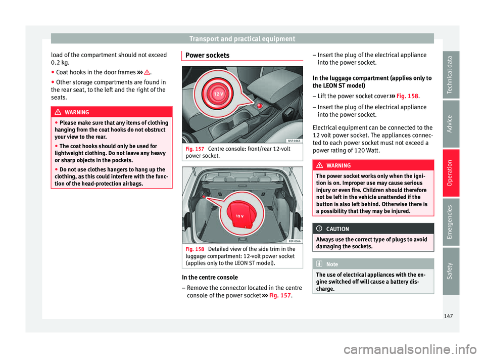
Fig. 157
Centre console: front/rear 12-volt
po w
er soc
ket. Fig. 158
Detailed view of the side trim in the
lug g
ag
e compartment: 12-volt power socket
(applies only to the LEON ST model). In the centre console
– Remove the connector located in the centre
con
so
le of the power socket ››› Fig. 157. –
Insert
the plug of the electrical appliance
into the power socket.
In the luggage compartment (applies only to
the LEON ST model)
– Lift the power socket cover ›››
Fig. 158.
– Insert the plug of the electrical appliance
into the pow
er socket.
Electrical equipment can be connected to the
12 volt power socket. The appliances connec-
ted to each power socket must not exceed a
power rating of 120 Watt. WARNING
The power socket works only when the igni-
tion is on. Impr
oper use may cause serious
injury or even fire. Children should therefore
not be left in the vehicle unattended if the
button is also left behind. Otherwise there is
a possibility that they may be injured. CAUTION
Always use the correct type of plugs to avoid
dam agin
g the sockets. Note
The use of electrical appliances with the en-
gine swit c
hed off will cause a battery dis-
charge. 147
Technical data
Advice
Operation
Emergencies
Safety
Page 153 of 308
Transport and practical equipment
Use of the net partition behind the
fr ont
se
at* 3 Applies to the model: LEON ST
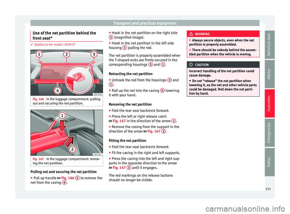
Fig. 166
In the luggage compartment: pulling
out and sec
urin
g the net partition. Fig. 167
In the luggage compartment: remov-
in g the net
p
artition. Pulling out and securing the net partition
● Pull up handle ››
›
Fig. 166 2 to remove the
net fr
om the c
asing 4 .●
Hook in the net
p
artition on the right side
3 (magnified image).
● Hook in the net partition in the left side
hou s
in
g 1 pulling the rod.
The net p
ar
tition is properly assembled when
the T-shaped ends are firmly secured in the
corresponding housings 3 and
1 .
R etr
actin
g the net partition
● Unhook the rod from the housings 3 and
1 .
● Roll up the net into the casing 4 lowering
it w
ith
your hand.
Removing the net partition
● Fold the rear seat backrests forward.
● Press the left or right release catch
›››
Fig. 167 in the direction of the arrow 1 .
● Remove the casing from the support in the
dir ection of
the arr
ow ››› Fig. 167 2 .
Fittin g the net
p
artition
● Fold the rear seat backrests forward.
● Fit the casing in the right and left supports.
● Press the casing into the left and right sup-
ports in the op
posite direction to the arrow
››› Fig. 167 2 until it engages.
The r ed m
ark
ings on the release buttons
should no longer be visible. WARNING
● Alw a
ys secure objects, even when the net
partition is properly assembled.
● There should be nobody behind the assem-
bled p
artition when the vehicle is moving. CAUTION
Incorrect handling of the net partition could
cau se d
amage.
● Do not “release” the net partition when
lowerin
g it, as the net and other vehicle parts
could be damaged. Roll down the net parti-
tion by hand. 151
Technical data
Advice
Operation
Emergencies
Safety
Page 154 of 308
Operation
Use of the net partition with the rear
se at
b
ackrests lowered 3 Applies to the model: LEON ST
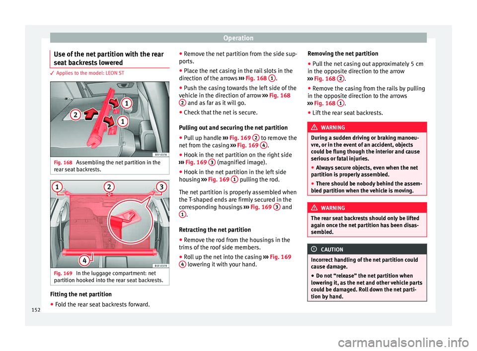
Fig. 168
Assembling the net partition in the
r e
ar se
at backrests. Fig. 169
In the luggage compartment: net
p ar
tition hook
ed into the rear seat backrests. Fitting the net partition
● Fold the rear seat backrests forward. ●
Remo
v
e the net partition from the side sup-
ports.
● Place the net casing in the rail slots in the
direction of the arr
ows ››› Fig. 168 1 .
● Push the casing towards the left side of the
v ehic
l
e in the direction of arrow ››› Fig. 168
2 and as far as it will go.
● Check that the net is secure.
P u
l
ling out and securing the net partition
● Pull up handle ›››
Fig. 169 2 to remove the
net fr
om the c
asing ››› Fig. 169 4 .
● Hook in the net partition on the right side
› ›
›
Fig. 169 3 (magnified image).
● Hook in the net partition in the left side
hou s
in
g ››› Fig. 169 1 pulling the rod.
The net p
ar
tition is properly assembled when
the T-shaped ends are firmly secured in the
corresponding housings ››› Fig. 169 3 and
1 .
R etr
actin
g the net partition
● Remove the rod from the housings in the
trims of the r
oof side members.
● Roll up the net into the casing ›››
Fig. 169
4 lowering it with your hand.Removing the net partition
●
Pull the net casing out approximately 5 cm
in the op po
s
ite direction to the arrow
››› Fig. 168 2 .
● Remove the casing from the rails by pulling
in the op po
s
ite direction to the arrows
››› Fig. 168 1 .
● Lift the rear seat backrests. WARNING
During a sudden driving or braking manoeu-
vre, or in the ev ent
of an accident, objects
could be flung though the interior and cause
serious or fatal injuries.
● Always secure objects, even when the net
partition i
s properly assembled.
● There should be nobody behind the assem-
bled p
artition when the vehicle is moving. WARNING
The rear seat backrests should only be lifted
again onc e the net
partition has been disas-
sembled. CAUTION
Incorrect handling of the net partition could
cau se d
amage.
● Do not “release” the net partition when
lowerin
g it, as the net and other vehicle parts
could be damaged. Roll down the net parti-
tion by hand. 152
Page 155 of 308
Transport and practical equipment
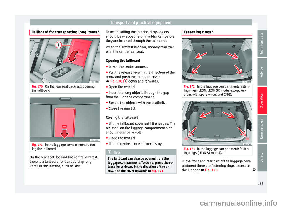
Tailboard for transporting long items* Fig. 170
On the rear seat backrest: opening
the t ai
l
board. Fig. 171
In the luggage compartment: open-
in g the t
ai
lboard. On the rear seat, behind the central armrest,
ther
e i
s
a tailboard for transporting long
items in the interior, such as skis. To avoid soiling the interior, dirty objects
should be wr
apped (e.g. in a blanket) before
they are inserted through the tailboard.
When the armrest is down, nobody may trav-
el in the centre rear seat.
Opening the tailboard
● Lower the centre armrest.
● Pull the release lever in the direction of the
arrow and p
ush the tailboard cover
››› Fig. 170 1 down and forwards.
● Open the rear lid.
● Insert the long objects through the gap
fr om the lug
g
age compartment.
● Secure the objects with the seatbelt.
● Close the rear lid.
Clos
ing the tailboard
● Lift the tailboard cover until it engages. The
red mark
on the luggage compartment side
should never be visible.
● Close the rear lid.
● Lift the centre armrest if necessary. Note
The tailboard can also be opened from the
lugg ag
e compartment. To do so, press the re-
lease lever down, in the direction of the ar-
row, and the cover upwards ››› Fig. 171. Fastening rings*
Fig. 172
In the luggage compartment: fasten-
in g rin
g
s (LEON/LEON SC model except ver-
sions with spare wheel and CNG). Fig. 173
In the luggage compartment: fasten-
in g rin
g
s (LEON ST model). In the front and rear part of the luggage com-
p
ar
tment
there are fastening rings to secure
the luggage ››› Fig. 173. »
153
Technical data
Advice
Operation
Emergencies
Safety
Page 156 of 308
Operation
In order to use the fastening rings, they must
be lif t
ed bef
orehand1)
. WARNING
If unsuitable or damaged belts or retaining
str ap
s are used, they could break in the event
of braking or an accident. Objects could then
be launched across the passenger compart-
ment and cause serious or fatal injuries.
● Always use belts or retaining straps that
are suit
able and in a good condition.
● Belts and retaining straps should be se-
curely
fastened to the fastening rings.
● Objects in the luggage compartment that
are un
secured could move suddenly and mod-
ify the handling of the vehicle.
● Secure all objects, little and large.
● Never exceed the maximum tensile load of
the fas
tening ring when securing objects.
● Never secure a child seat to the fastening
rings. Note
● The max imum t
ensile load that the fasten-
ing rings can support is 3.5 kN.
● Belts and securing systems for the appro-
priate lo
ad can be obtained from specialised
dealerships. SEAT recommends visiting a
SEAT dealership for this. ●
The fa s
tening rings are rendered unusable
for versions with spare wheel and CNG. Retaining hooks
Fig. 174
In the luggage compartment: retain-
in g hook
s
(LEON/LEON SC model). Fig. 175
In the luggage compartment: retain-
ing hook s
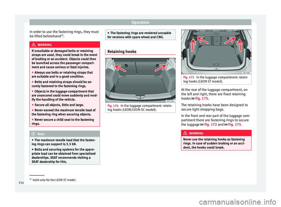
(LEON ST model). At the rear of the luggage compartment, on
the l
ef
t
and right, there are fixed retaining
hooks ››› Fig. 175.
The retaining hooks have been designed to
secure light shopping bags.
In the front and rear part of the luggage com-
partment there are fastening rings to secure
the luggage ››› Fig. 172 and ››› Fig. 173. WARNING
Never use the retaining hooks as fastening
ring s. In c
ase of sudden braking or an acci-
dent, the hooks could break. 1)
Valid only for the LEON ST model.
154
Page 158 of 308
Operation
Luggage compartment variable floor 3 Applies to the model: LEON/LEON SC
Fig. 178
Luggage compartment: variable
floor Fig. 179
Luggage compartment: variable
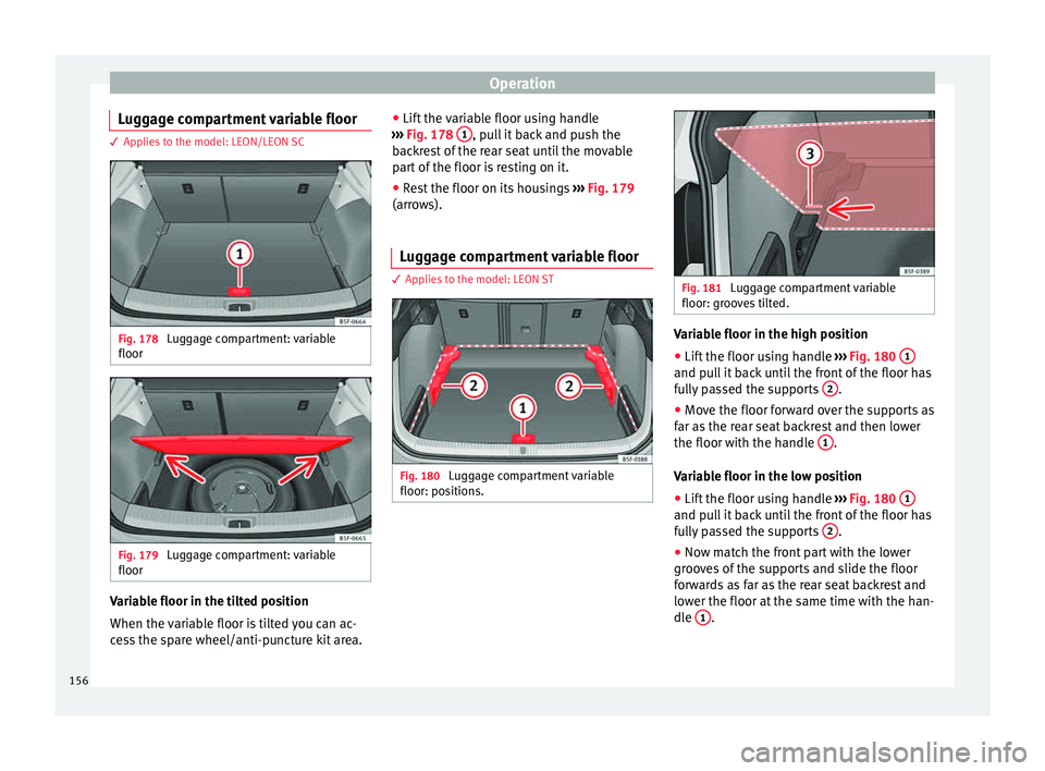
floor Variable floor in the tilted position
When the
v
ari
able floor is tilted you can ac-
cess the spare wheel/anti-puncture kit area. ●
Lift the
variable floor using handle
››› Fig. 178 1 , pull it back and push the
b ac
k
rest of the rear seat until the movable
part of the floor is resting on it.
● Rest the floor on its housings ›››
Fig. 179
(arrows).
Luggage compartment variable floor 3 Applies to the model: LEON ST
Fig. 180
Luggage compartment variable
floor: po s
ition
s. Fig. 181
Luggage compartment variable
floor: groo v
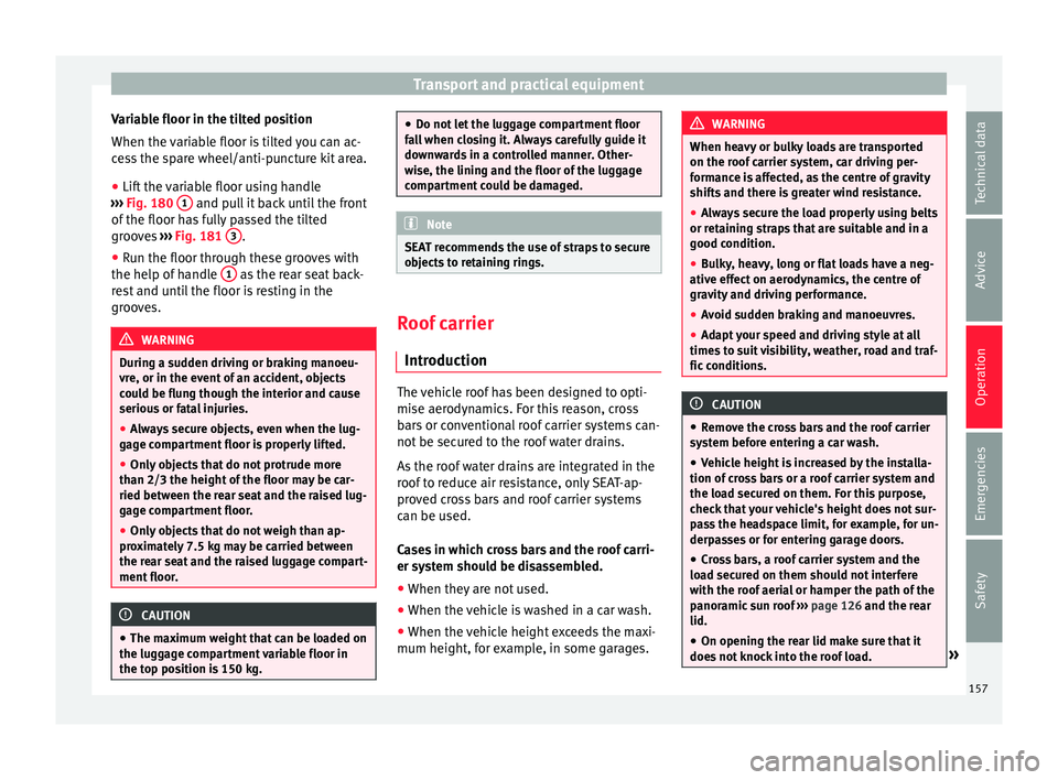
es tilted. Variable floor in the high position
● Lift the floor using handle ››
›
Fig. 180 1 and pull it back until the front of the floor has
f
u
l
ly passed the supports 2 .
● Move the floor forward over the supports as
f ar a
s
the rear seat backrest and then lower
the floor with the handle 1 .
V ari
ab
le floor in the low position
● Lift the floor using handle ›››
Fig. 180 1 and pull it back until the front of the floor has
f
u
l
ly passed the supports 2 .
● Now match the front part with the lower
gr oo
v
es of the supports and slide the floor
forwards as far as the rear seat backrest and
lower the floor at the same time with the han-
dle 1 .
156
Page 159 of 308
Transport and practical equipment
Variable floor in the tilted position
When the v
ari
able floor is tilted you can ac-
cess the spare wheel/anti-puncture kit area.
● Lift the variable floor using handle
›››
Fig. 180 1 and pull it back until the front
of the floor h
a
s fully passed the tilted
grooves ››› Fig. 181 3 .
● Run the floor through these grooves with
the help of h
andl
e 1 as the rear seat back-
r e
s
t and until the floor is resting in the
grooves. WARNING
During a sudden driving or braking manoeu-
vre, or in the ev ent
of an accident, objects
could be flung though the interior and cause
serious or fatal injuries.
● Always secure objects, even when the lug-
gage c
ompartment floor is properly lifted.
● Only objects that do not protrude more
than 2/3 the height of
the floor may be car-
ried between the rear seat and the raised lug-
gage compartment floor.
● Only objects that do not weigh than ap-
prox
imately 7.5 kg may be carried between
the rear seat and the raised luggage compart-
ment floor. CAUTION
● The max imum w
eight that can be loaded on
the luggage compartment variable floor in
the top position is 150 kg. ●
Do not l et
the luggage compartment floor
fall when closing it. Always carefully guide it
downwards in a controlled manner. Other-
wise, the lining and the floor of the luggage
compartment could be damaged. Note
SEAT recommends the use of straps to secure
o b j
ects to retaining rings. Roof carrier
Intr oduction The vehicle roof has been designed to opti-
mi
se aer
ody
namics. For this reason, cross
bars or conventional roof carrier systems can-
not be secured to the roof water drains.
As the roof water drains are integrated in the
roof to reduce air resistance, only SEAT-ap-
proved cross bars and roof carrier systems
can be used.
Cases in which cross bars and the roof carri-
er system should be disassembled.
● When they are not used.
● When the vehicle is washed in a car wash.
● When the vehicle height exceeds the maxi-
mum height, for e x
ample, in some garages. WARNING
When heavy or bulky loads are transported
on the roof c
arrier system, car driving per-
formance is affected, as the centre of gravity
shifts and there is greater wind resistance.
● Always secure the load properly using belts
or retainin
g straps that are suitable and in a
good condition.
● Bulky, heavy, long or flat loads have a neg-
ative effect
on aerodynamics, the centre of
gravity and driving performance.
● Avoid sudden braking and manoeuvres.
● Adapt your speed and driving style at all
times t
o suit visibility, weather, road and traf-
fic conditions. CAUTION
● Remo v
e the cross bars and the roof carrier
system before entering a car wash.
● Vehicle height is increased by the installa-
tion of cr
oss bars or a roof carrier system and
the load secured on them. For this purpose,
check that your vehicle's height does not sur-
pass the headspace limit, for example, for un-
derpasses or for entering garage doors.
● Cross bars, a roof carrier system and the
load sec
ured on them should not interfere
with the roof aerial or hamper the path of the
panoramic sun roof ››› page 126 and the rear
lid.
● On opening the rear lid make sure that it
does not
knock into the roof load. » 157
Technical data
Advice
Operation
Emergencies
Safety
Page 160 of 308
Operation
For the sake of the environment
When cross bars and a roof carrier system are
ins t
alled, the increased air resistance means
that the vehicle uses more fuel. Attach the cross bars of the roof carri-
er sys
t
em Fig. 182
Leon/Leon SC: attachment points for
the r oof
r
ailings for the roof carrier system. Fig. 183
Leon ST: attachment points for the
roof r
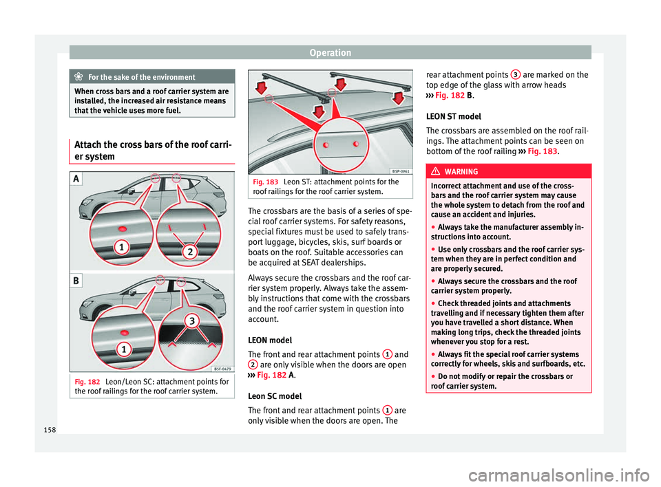
ailings for the roof carrier system. The crossbars are the basis of a series of spe-
c
i
al
roof carrier systems. For safety reasons,
special fixtures must be used to safely trans-
port luggage, bicycles, skis, surf boards or
boats on the roof. Suitable accessories can
be acquired at SEAT dealerships.
Always secure the crossbars and the roof car-
rier system properly. Always take the assem-
bly instructions that come with the crossbars
and the roof carrier system in question into
account.
LEON model
The front and rear attachment points 1 and
2 are only visible when the doors are open
› ›
›
Fig. 182 A.
Leon SC model
The front and rear attachment points 1 are
on ly
visible when the doors are open. The rear attachment points
3 are marked on the
t op edg
e of
the glass with arrow heads
››› Fig. 182 B.
LEON ST model
The crossbars are assembled on the roof rail-
ings. The attachment points can be seen on
bottom of the roof railing ››› Fig. 183. WARNING
Incorrect attachment and use of the cross-
bar s
and the roof carrier system may cause
the whole system to detach from the roof and
cause an accident and injuries.
● Always take the manufacturer assembly in-
structions
into account.
● Use only crossbars and the roof carrier sys-
tem when they ar
e in perfect condition and
are properly secured.
● Always secure the crossbars and the roof
carrier sys
tem properly.
● Check threaded joints and attachments
travel
ling and if necessary tighten them after
you have travelled a short distance. When
making long trips, check the threaded joints
whenever you stop for a rest.
● Always fit the special roof carrier systems
correctly
for wheels, skis and surfboards, etc.
● Do not modify or repair the crossbars or
roof c
arrier system.158
Page 162 of 308
Operation
WARNING
Reduced visibility through the windows in-
cr e
ases the risk of serious accidents.
● Always ensure that all windows are free of
ice and sno
w, and that they are not fogged,
so as to maintain good visibility of everything
outside.
● The maximum heat output required to de-
fros
t windows as quickly as possible is only
available when the engine has reached its
normal running temperature. Only drive when
you have good visibility.
● Always ensure that you use the heating
syst
em, fresh air system, air conditioner and
the heated rear window to maintain good visi-
bility to the outside.
● Never leave the air recirculation on for a
long period of time. If
the cooling system is
switched off and air recirculation mode
switched on, the windows can mist over very
quickly, considerably limiting visibility.
● Switch air recirculation mode off when it is
not requir
ed. WARNING
Stuffy or used air will increase fatigue and re-
duce driv er c
oncentration possibly resulting
in a serious accident.
● Never leave the fresh air fan turned off or
use the air rec
irculation for long periods of
time; the air in the vehicle interior will not be
refreshed. CAUTION
● Swit c
h the air conditioner off if you think it
may be broken. This will avoid additional
damage. Have the air conditioner checked by
a specialised workshop.
● Repairs to the air conditioner require spe-
cia
list knowledge and special tools. SEAT rec-
ommends visiting a SEAT Official Service. Note
● When the coo lin
g system is turned off, air
coming from the outside will not be dried. To
prevent fogging of the windows, SEAT recom-
mends leaving the cooling system (compres-
sor) turned on. To do this, press the button . The button lamp should light up.
● The maximum heat output required to de-
fro s
t windows as quickly as possible is only
available when the engine has reached its
normal running temperature.
● Keep the air intake slots in front of the
winds
creen free of snow, ice and leaves to en-
sure heating and cooling are not impaired,
and to prevent the windows from misting
over. Adjust using the Easy Connect sys-
t
em* 3 Applies to vehicles with a Touch/Colour Media
S y
stem.
In the Easy Connect system it is also possible
to perform various adjustments to the Clima-
tronic.
Open the air conditioner menu
● Press the Setup button.
● OR: press the MENU button in Easy Con-
nect. W
ith the rotating switch select the air
conditioner menu and open it.
On the touch screen you can see and change
the current settings, for example, the temper-
ature set for the driver and passenger sides,
the air distribution and the fan speed. With
button the driver and passenger side
t emper
at
ures are synchronised ›››
Book-
let Media System Touch/Colour, chapter Air
conditioning.
To switch a function on or off, or to select a
submenu, you must press the corresponding
function button.
For more information about functions
››› page 110.
160
Page 168 of 308
Operation
remains switched on. Make sure that the igni-
tion is
sw
itched off before leaving the
vehicle, otherwise the battery could dis-
charge. Braking and parking
Us in
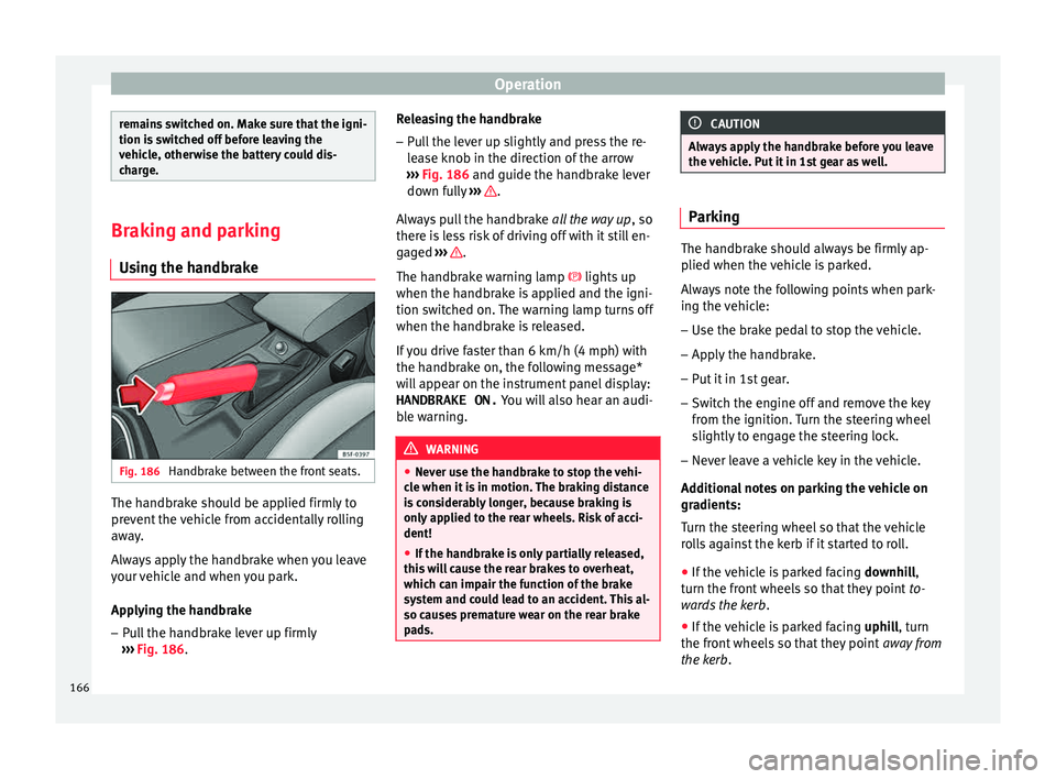
g the handbrake Fig. 186
Handbrake between the front seats. The handbrake should be applied firmly to
pr
ev
ent
the vehicle from accidentally rolling
away.
Always apply the handbrake when you leave
your vehicle and when you park.
Applying the handbrake
– Pull the handbrake lever up firmly
›››
Fig. 186. Releasing the handbrake
– Pull the lever up slightly and press the re-
lea
se knob in the direction of the arrow
››› Fig. 186 and guide the handbrake lever
down fully ››› .
A lw
a
ys pull the handbrake all the way up, so
there is less risk of driving off with it still en-
gaged ››› .
The h andbr
ak
e warning lamp lights up
when the handbrake is applied and the igni-
tion switched on. The warning lamp turns off
when the handbrake is released.
If you drive faster than 6 km/h (4 mph) with
the handbrake on, the following message*
will appear on the instrument panel display: HANDBRAKE ON. You will also hear an audi-
ble warning. WARNING
● Never u se the h
andbrake to stop the vehi-
cle when it is in motion. The braking distance
is considerably longer, because braking is
only applied to the rear wheels. Risk of acci-
dent!
● If the handbrake is only partially released,
this w
ill cause the rear brakes to overheat,
which can impair the function of the brake
system and could lead to an accident. This al-
so causes premature wear on the rear brake
pads. CAUTION
Always apply the handbrake before you leave
the v ehic
le. Put it in 1st gear as well. Parking
The handbrake should always be firmly ap-
plied when the
v
ehicle is parked.
Always note the following points when park-
ing the vehicle: – Use the brake pedal to stop the vehicle.
– Apply the handbrake.
– Put it in 1st gear.
– Switch the engine off and remove the key
from the ignition. T
urn the steering wheel
slightly to engage the steering lock.
– Never leave a vehicle key in the vehicle.
Additiona
l notes on parking the vehicle on
gradients:
Turn the steering wheel so that the vehicle
rolls against the kerb if it started to roll.
● If the vehicle is parked facing downhil
l,
turn the front wheels so that they point to-
wards the kerb .
● If the vehicle is parked facing uphill
, turn
the front wheels so that they point away from
the kerb.
166