technical specifications Seat Toledo 2013 Owner's Guide
[x] Cancel search | Manufacturer: SEAT, Model Year: 2013, Model line: Toledo, Model: Seat Toledo 2013Pages: 258, PDF Size: 3.94 MB
Page 45 of 258
43
Airbag system
WARNING (Continued)
● Do not attempt to modify components of the airbag system in any
way.
● The side and head airbags are managed through sensors located in
the interior of the front doors. To ensure the correct operation of the side
and head airbags neither the doors nor the door panels should be modi-
fied in any way (e.g. fitting loudspeakers). If the front door is damaged,
the airbag system may not work correctly. All work carried out on the
front door must be done in a specialised workshop.
Deactivating airbags Deactivating airbags
The deactivation of airbags corresponds only to certain cases, i.e. if:
● a child seat is required in the front passenger seat with the child facing
in the opposite direction to the direction of travel (in some countries, due to
divergent legal requirements, facing in the direction of travel) ⇒ page 48;
● despite the driver seat being in the correct position, a minimum dis-
tance of 25 cm cannot be maintained between the centre of the steering
wheel and the driver's torso.
● installation of special devices is required in the steering wheel area due
to a physical disability.
● if you have special seats installed (e.g. an orthopaedic seat without side
airbag).
The front passenger front airbag can be disabled using the switch
⇒ page 44.
We recommend that you contact an authorised SEAT dealer for the disabling
of other airbags. Airbag system control
The airbag system availability is controlled electronically, regardless of
whether an airbag is disabled.
If an airbag was disabled using a diagnostics system:
●
the airbag system warning lamp lights up after switching on the igni-
tion for about 4 seconds, and then flashes for about 12 seconds
If the airbag has been disabled with the airbag switch on the side of the
dash panel:
● the airbag control lamp will light up for about 4 seconds after the ig-
nition is switched on.
● the airbag is disabled, signalled with the warning lamp which
lights up with the word placed in the centre part of the
dash panel ⇒ Fig. 24 3
.
Note
● Respect the current legislation in your country regarding the deactiva-
tion of airbags
● At your authorised SEAT dealer you can find information on which vehi-
cle airbags can be deactivated.
Safety FirstOperating instructionsPractical TipsTechnical specifications
Page 47 of 258
45
Airbag system
WARNING (Continued)
● Never leave the key in the airbag deactivation switch as it could get
damaged or activate or deactivate the airbag during driving.
● If the control lamp (airbag deactivated) flashes, the front pas-
senger front airbag will not trigger in the event of an accident! Have the
system immediately checked by an Official Service.
Safety FirstOperating instructionsPractical TipsTechnical specifications
Page 49 of 258
47
Child safety
WARNING
● Never install a child seat facing backwards on the front passenger
seat unless the front passenger front airbag has been disabled. Risk of
potentially fatal injuries to the child! However, if it is necessary, in excep-
tional cases, to transport a child in the front passenger seat, the front
passenger front airbag must always be disabled ⇒ page 43. If the pas-
senger seat has a height adjustment option, move it to the highest posi-
tion.
● For those vehicles that do not include a key lock switch to deactivate
the airbag, the vehicle must be taken to a Technical Service.
● All vehicle occupants, especially children, must assume the proper
sitting position and be properly belted in while travelling.
● Never hold children or babies on your lap, this can result in potential-
ly fatal injuries to the child!
● Never allow a child to be transported in a vehicle without being prop-
erly secured, or to stand up or kneel on a seat while travelling. In an acci-
dent, the child could be flung through the vehicle, causing possibly fatal
injuries to themselves and to the other vehicle occupants.
● If children assume an improper sitting position when the vehicle is
moving, they expose themselves to greater risk of injury in the event of a
sudden braking manoeuvre or in an accident. This is particularly impor-
tant if the child is travelling on the front passenger seat and the airbag
system is triggered in an accident; as this could cause serious injury or
even death.
● A suitable child seat can protect your child!
● Never leave an unsupervised child alone on a child seat or in the vehi-
cle.
● Depending on weather conditions, it may become extremely hot or
cold inside the vehicle. This can be fatal.WARNING (Continued)
● Children who are less than 1.5 metres tall must not wear a normal
seat belt without a child seat, as this could cause injuries to the abdomi-
nal and neck areas during a sudden braking manoeuvre or in an accident.
● Do not allow the seat belt to become twisted or jammed, or to rub on
any sharp edges.
● Incorrectly worn seat belts can cause injuries even in a minor colli-
sion or in sudden braking manoeuvres.
● The seat belt provides maximum protection only when the seat belt is
properly positioned ⇒ page 26, Seat belts.
● Only one child may occupy a child seat ⇒ page 48, Child seats.
Safety FirstOperating instructionsPractical TipsTechnical specifications
Page 51 of 258

49
Child safety
Group 1 child seats
A suitable child seat and a correctly adjusted seat belt can
help you to protect your child.
Fig. 26 A category 1 for-
ward-facing child seat fit-
ted on the rear seat
Child seats using the ISOFIX system or seats in which the child faces the
rear of the vehicle are most appropriate for babies and small children
weighing between 9 and 18 kg.
Follow the manufacturer's instructions and observe any statutory require-
ments when installing and using child seats.
We recommend you to always include the manufacturer's Child Seat Instruc-
tion Manual together with the on-board documentation.
WARNING
Read and always observe information and warnings concerning the use
of child seats ⇒ page 46.
Group 2 and 3 child seats
A suitable child seat and a correctly adjusted seat belt can
help you to protect your child.
Fig. 27 Forward-facing
child seat installed on
rear seat
Follow the manufacturer's instructions and observe any statutory require-
ments when installing and using child seats.
We recommend you to always include the manufacturer's Child Seat Instruc-
tion Manual together with the on-board documentation.
Group 2 child seats
Children under 7 years of age weighing between 15 and 25 kg are best pro-
tected by group 2 child seats together with properly adjusted seat belts.
Group 3 child seats
Children over 7 years of age weighing between 22 and 36 kg but less than
1.5 metres tall are best protected by child seats with head restraints togeth-
er with properly worn seat belts ⇒ Fig. 27.
Safety FirstOperating instructionsPractical TipsTechnical specifications
Page 53 of 258

51
Child safety
Securing child seats
Ways to secure a child seat
A child seat can be secured differently on the rear seat and
on the front passenger seat. You can secure a child seat to the rear seat or front passenger seat in the
following ways:
● Child seats in groups 0 to 3 can be secured with a seat belt.
● Child seats in groups 0, 0+ and 1 with the ISOFIX and Top Tether* sys-
tems can be secured without using the seatbelt, thanks to the ISOFIX and
Top Tether* securing rings ⇒ page 52.
CategoryWeightSeat locationsFront passen-
gerRear outerRear centre
Group 0<10 kgU*U/LUGroup 0+<13 kgU*U/LUGroup 19-18 kgU*U/LUGroup 2/315-36 kgU*UU
Suitable for universal approved restraining systems for use in this age
category (universal retention systems are those fitted using the adult
seat belt).
Move the front passenger seat as far back as possible, as high as pos-
sible and always disable the airbag.
Suitable for retention systems using the ISOFIX and Top Tether* an-
chors.
U:
*:
L:
WARNING
● When travelling, children must be secured in the vehicle with a re-
straint system suitable for age, weight and size.
● Never install a child seat facing backwards on the front passenger
seat unless the front passenger airbag has been disabled. This could
cause fatal injuries to the child! However, if, in exceptional cases, it is
necessary to transport a child in the front passenger seat, the front pas-
senger airbag ⇒ page 43 must always be disabled and the seat adjusted
to its highest position, where possible.
● Read and always observe information and warnings concerning the
use of child seats ⇒ page 46.
Safety FirstOperating instructionsPractical TipsTechnical specifications
Page 55 of 258

53
Child safety
Safety FirstOperating instructionsPractical TipsTechnical specifications
Page 57 of 258
55
Controls and displays
Operating instructions Controls and displays
Overview
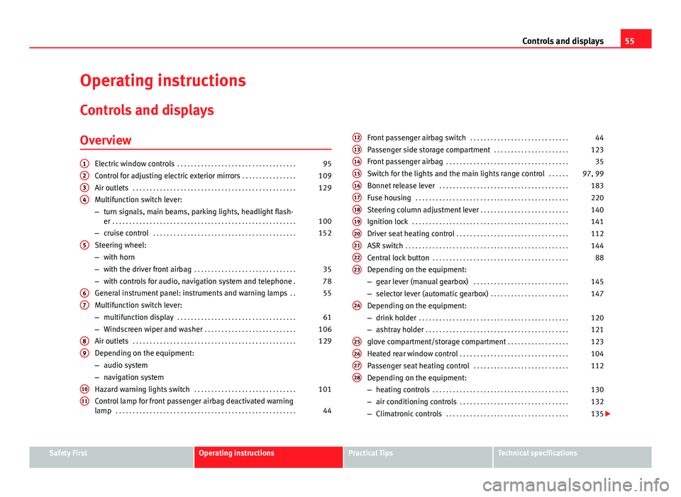
Electric window controls . . . . . . . . . . . . . . . . . . . . . . . . . . . . . . . . . . . 95
Control for adjusting electric exterior mirrors . . . . . . . . . . . . . . . .109
Air outlets . . . . . . . . . . . . . . . . . . . . . . . . . . . . . . . . . . . . . . . . . . . . . . . . 129
Multifunction switch lever:
– turn signals, main beams, parking lights, headlight flash-
er . . . . . . . . . . . . . . . . . . . . . . . . . . . . . . . . . . . . . . . . . . . . . . . . . . . . . . 100
– cruise control . . . . . . . . . . . . . . . . . . . . . . . . . . . . . . . . . . . . . . . . . . 152
Steering wheel:
– with horn
– with the driver front airbag . . . . . . . . . . . . . . . . . . . . . . . . . . . . . . 35
– with controls for audio, navigation system and telephone .78
General instrument panel: instruments and warning lamps . .55
Multifunction switch lever:
– multifunction display . . . . . . . . . . . . . . . . . . . . . . . . . . . . . . . . . . . 61
– Windscreen wiper and washer . . . . . . . . . . . . . . . . . . . . . . . . . . . 106
Air outlets . . . . . . . . . . . . . . . . . . . . . . . . . . . . . . . . . . . . . . . . . . . . . . . . 129
Depending on the equipment:
– audio system
– navigation system
Hazard warning lights switch . . . . . . . . . . . . . . . . . . . . . . . . . . . . . . 101
Control lamp for front passenger airbag deactivated warning
lamp . . . . . . . . . . . . . . . . . . . . . . . . . . . . . . . . . . . . . . . . . . . . . . . . . . . . . 44
1234
5
67
89
1011
Front passenger airbag switch
. . . . . . . . . . . . . . . . . . . . . . . . . . . . . 44
Passenger side storage compartment . . . . . . . . . . . . . . . . . . . . . .123
Front passenger airbag . . . . . . . . . . . . . . . . . . . . . . . . . . . . . . . . . . . . 35
Switch for the lights and the main lights range control . . . . . .97, 99
Bonnet release lever . . . . . . . . . . . . . . . . . . . . . . . . . . . . . . . . . . . . . . 183
Fuse housing . . . . . . . . . . . . . . . . . . . . . . . . . . . . . . . . . . . . . . . . . . . . . 220
Steering column adjustment lever . . . . . . . . . . . . . . . . . . . . . . . . . . 140
Ignition lock . . . . . . . . . . . . . . . . . . . . . . . . . . . . . . . . . . . . . . . . . . . . . . 141
Driver seat heating control . . . . . . . . . . . . . . . . . . . . . . . . . . . . . . . . . 112
ASR switch . . . . . . . . . . . . . . . . . . . . . . . . . . . . . . . . . . . . . . . . . . . . . . . . 144
Central lock button . . . . . . . . . . . . . . . . . . . . . . . . . . . . . . . . . . . . . . . . 88
Depending on the equipment:
– gear lever (manual gearbox) . . . . . . . . . . . . . . . . . . . . . . . . . . . . 145
– selector lever (automatic gearbox) . . . . . . . . . . . . . . . . . . . . . . .147
Depending on the equipment:
– drink holder . . . . . . . . . . . . . . . . . . . . . . . . . . . . . . . . . . . . . . . . . . . . 120
– ashtray holder . . . . . . . . . . . . . . . . . . . . . . . . . . . . . . . . . . . . . . . . . . 121
glove compartment/storage compartment . . . . . . . . . . . . . . . . . .123
Heated rear window control . . . . . . . . . . . . . . . . . . . . . . . . . . . . . . . . 104
Passenger seat heating control . . . . . . . . . . . . . . . . . . . . . . . . . . . . 112
Depending on the equipment:
– heating controls . . . . . . . . . . . . . . . . . . . . . . . . . . . . . . . . . . . . . . . . 130
– air conditioning controls . . . . . . . . . . . . . . . . . . . . . . . . . . . . . . . . 132
– Climatronic controls . . . . . . . . . . . . . . . . . . . . . . . . . . . . . . . . . . . . 135
121314151617181920212223
24
25262728
Safety FirstOperating instructionsPractical TipsTechnical specifications
Page 59 of 258
57
Controls and displays
Instruments and warning lamps
General instrument panel – summary
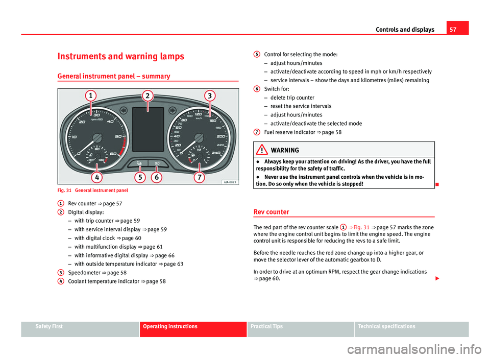
Fig. 31 General instrument panel Rev counter ⇒ page 57
Digital display:
– with trip counter
⇒ page 59
– with service interval display
⇒ page 59
– with digital clock
⇒ page 60
– with multifunction display
⇒ page 61
– with informative digital display
⇒ page 66
– with outside temperature indicator
⇒ page 63
Speedometer ⇒ page 58
Coolant temperature indicator ⇒ page 58
1
2
34
Control for selecting the mode:
–
adjust hours/minutes
– activate/deactivate according to speed in mph or km/h respectively
– service intervals – show the days and kilometres (miles) remaining
Switch for:
– delete trip counter
– reset the service intervals
– adjust hours/minutes
– activate/deactivate the selected mode
Fuel reserve indicator ⇒ page 58
WARNING
● Always keep your attention on driving! As the driver, you have the full
responsibility for the safety of traffic.
● Never use the instrument panel controls when the vehicle is in mo-
tion. Do so only when the vehicle is stopped!
Rev counter
The red part of the rev counter scale 1 ⇒ Fig. 31 ⇒
page 57 marks the zone
where the engine control unit begins to limit the engine speed. The engine
control unit is responsible for reducing the revs to a safe limit.
Before the needle reaches the red zone change up into a higher gear, or
move the selector lever of the automatic gearbox to D.
In order to drive at an optimum RPM, respect the gear change indications
⇒ page 60.
5
6
7
Safety FirstOperating instructionsPractical TipsTechnical specifications
Page 61 of 258
59
Controls and displays
Trip counter*
Daily trip counter (trip)
The daily trip counter indicates the journey that has been covered since the
last time the function was reset in 100 metre sections.
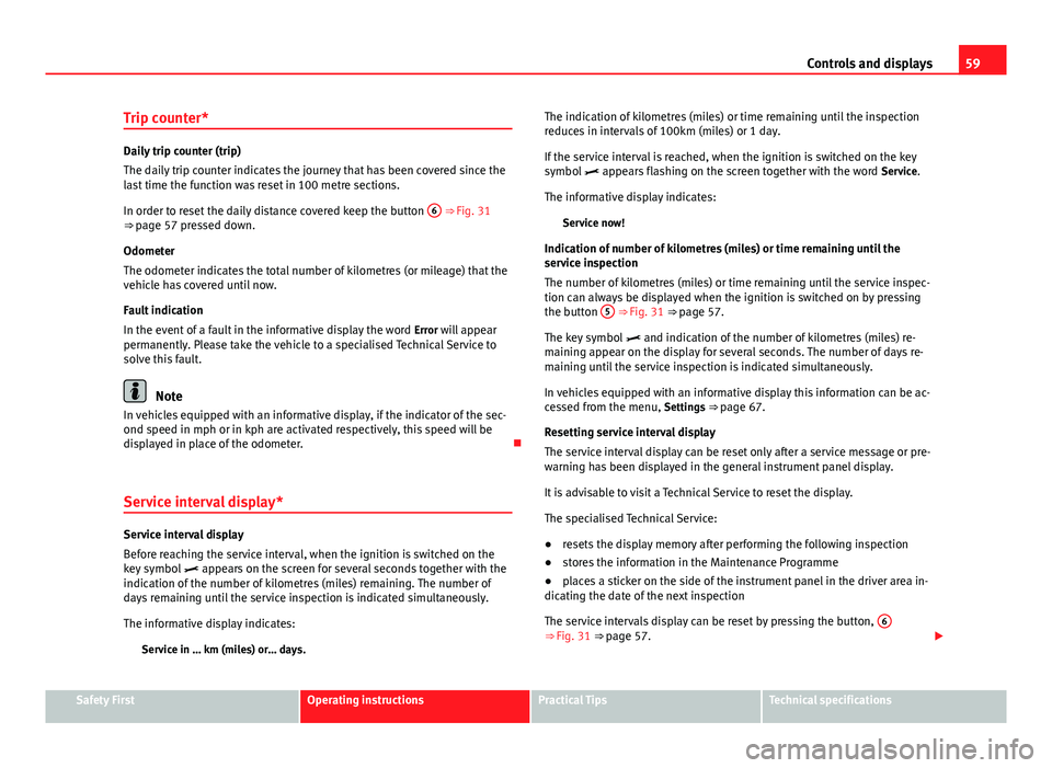
In order to reset the daily distance covered keep the button 6
⇒ Fig. 31
⇒ page 57 pressed down.
Odometer
The odometer indicates the total number of kilometres (or mileage) that the
vehicle has covered until now.
Fault indication
In the event of a fault in the informative display the word Error will appear
permanently. Please take the vehicle to a specialised Technical Service to
solve this fault.
Note
In vehicles equipped with an informative display, if the indicator of the sec-
ond speed in mph or in kph are activated respectively, this speed will be
displayed in place of the odometer.
Service interval display*
Service interval display
Before reaching the service interval, when the ignition is switched on the
key symbol appears on the screen for several seconds together with the
indication of the number of kilometres (miles) remaining. The number of
days remaining until the service inspection is indicated simultaneously.
The informative display indicates:
Service in … km (miles) or… days. The indication of kilometres (miles) or time remaining until the inspection
reduces in intervals of 100km (miles) or 1 day.
If the service interval is reached, when the ignition is switched on the key
symbol
appears flashing on the screen together with the word Service.
The informative display indicates: Service now!
Indication of number of kilometres (miles) or time remaining until the
service inspection
The number of kilometres (miles) or time remaining until the service inspec-
tion can always be displayed when the ignition is switched on by pressing
the button 5
⇒ Fig. 31 ⇒
page 57.
The key symbol and indication of the number of kilometres (miles) re-
maining appear on the display for several seconds. The number of days re-
maining until the service inspection is indicated simultaneously.
In vehicles equipped with an informative display this information can be ac-
cessed from the menu, Settings ⇒ page 67.
Resetting service interval display
The service interval display can be reset only after a service message or pre-
warning has been displayed in the general instrument panel display.
It is advisable to visit a Technical Service to reset the display.
The specialised Technical Service:
● resets the display memory after performing the following inspection
● stores the information in the Maintenance Programme
● places a sticker on the side of the instrument panel in the driver area in-
dicating the date of the next inspection
The service intervals display can be reset by pressing the button, 6
⇒ Fig. 31 ⇒
page 57.
Safety FirstOperating instructionsPractical TipsTechnical specifications
Page 63 of 258

61
Controls and displays
Multi-function display* (on board computer)
Introduction
The multifunction display can only be operated when the ignition is switch-
ed on. When the ignition is switched on the last function selected before it
was switched off is displayed.
The multifunction display data is shown on the screen ⇒ Fig. 33
⇒ page 61.
In vehicles fitted with an informative display ⇒ page 66 the system can be
adjusted so that certain data is not shown.
WARNING
● Always keep your attention on driving! As the driver, you have the full
responsibility for the safety of traffic.
● Do not rely only on the outside temperature indicator to verify wheth-
er the road surface is frozen. This is because with an outside temperature
of +4 °C (+39 °F) ice can generate on the road - Warning of frozen road
surface!
Note
● Models for certain countries can show the values in imperial units.
● If the second speed in mph (km/h) is displayed, the current speed in
km/h (mph) is not displayed on the screen. Memory
Fig. 33 Multifunction
display
The multifunction display has two automatic memories. The selected mem-
ory is displayed on the screen ⇒ Fig. 33.
The current journey data (memory 1) is always displayed when the number
1 appears on the display. When number 2 appears on the display, the total
distance travelled is shown (memory 2).
The memory is selected depending on the equipment:
● by pressing the lever's B
button briefly
⇒ Fig. 34 ⇒ page 62, or else
● briefly pressing the right thumbwheel of the multifunction steering
wheel 1
⇒
Fig. 35.
Current journey memory (memory 1)
The current journey memory collects data from the moment the ignition is
switched on until it is switched off. If the journey is continued within two
hours of switching off the ignition, the new values will be added to the ex-
isting trip recorder memory. The memory will automatically be deleted if the
journey is interrupted for more than two hours.
Total distance travelled memory (memory 2)
The total distance travelled memory collects journey data from any number
of individual journeys up to a maximum of 19 hours and 59 minutes and
Safety FirstOperating instructionsPractical TipsTechnical specifications