warning Seat Toledo 2017 User Guide
[x] Cancel search | Manufacturer: SEAT, Model Year: 2017, Model line: Toledo, Model: Seat Toledo 2017Pages: 248, PDF Size: 5.86 MB
Page 29 of 248

The essentials
The following menus can be displayed:
● Stop
● Lap
● Pause
● Partial time
● Statistics
Ch an
g
e from one menu to another
● Vehicles without multifunction steering
wheel:
press the rocker switch in the
w ind
s
creen wiper lever.
● Vehicles with multifunction steering wheel:
pres
s or
.
Menu “Stop”
Start
The timer starts.
If there are existing laps and they are in-
cluded in the statistics, it will begin with
the number of laps in question.
It is only possible to begin with a new first
lap if the statistics have been reset first in
the Statistics
menu.
Since
startThe timer begins when the vehicle sets
off.
If the vehicle is already moving, the timer
begins once the vehicle has stopped.
Statis-
ticsThe Statistics menu is displayed on
the screen.
Menu “Lap”
New lap
The timer of the current lap stops and a
new lap starts immediately. The time for
the lap you have just completed is inclu-
ded in the statistics.
Partial timeFor about 5 seconds a partial time is dis-
played. The timer continues in parallel.
StopThe current lap timer will be interrupted.
The lap does not end. The Pause menu is
displayed.
Menu “Pause”
ContinueThe interrupted timer continues.
New lapA new timer starts. The halted lap ends
and is included in the statistics.
Interr. lapThe timer of the current lap ends and is
cancelled. It is not included in the statis-
tics.
EndThe current timer ends. The lap is inclu-
ded in the statistics.
Menu “Partial time”
Partial
timeFor about 5 seconds a partial time is dis-
played. The timer continues in parallel.
New lap
The timer of the current lap stops and a
new lap starts immediately. The time for
the lap you have just completed is inclu-
ded in the statistics.
Menu “Partial time”
StopThe current lap timer will be interrupted.
The lap does not end. The Pause menu is
displayed.
Menu “Statistics”
View of the latest lap times:
– total time
– best lap time
– worst lap time
– average lap duration
A maximum of 10 laps is possible, and a
total duration of 99 hours, 59 minutes
and 59 seconds.
If one of the 2 limits is reached, you will
have to reset the statistics in order to be-
gin a new timer.
BackThis returns to the previous menu.
Reset-
ting to
zeroAll the memorised statistical data are re-
set. WARNING
Do your best to avoid handling the timer
whil e driv
ing.
● Only set the timer or consult statistics
when the vehic
le is stationary.
● While driving, do not handle the timer in
complic
ated driving situations. 27
Page 30 of 248

The essentials
Status display Bonnet, r e
ar lid and door
s openFig. 37
A: bonnet open; B: rear lid open; C:
fr ont
l
eft door open; D: rear right door open
(5-door vehicles only). When the ignition is switched on or when
driv
in
g, the bonnet, r
ear lid or doors that are
open will be indicated on the instrument pan-
el display, and, as applicable, this will be in-
dicated audibly. The display may vary accord-
ing to the type of instrument panel fitted.
Illustra- tionKey to ››› Fig. 37
A Do not continue driving!
The bonnet is open or is not properly
closed ››› page 204.
B Do not continue driving!
The rear lid is open or is not properly
closed ››› page 10.
C, D Do not continue driving!
A vehicle door is open or is not properly
closed ››› page 111.
›››
page 97 Warning and information messages
The system runs a check on certain compo-
nents
and f
u
nctions when the ignition is
switched on and while the vehicle is moving.
Faults in the operation are displayed on the
screen using red and yellow symbols and
messages on the instrument panel display
( ››› page 33, ››› page 33) and, in some ca-
ses, with audible warnings. The display may
vary according to the type of instrument pan-
el fitted.
Priority 1 warning (red symbols)
Symbol flashing or lit; partly combined with audible
warnings.
Stop the vehicle! It is dangerous ››› in Control and
warning lamps on page 101 !
Check the function that is faulty and repair it. If necessa-
ry, request assistance from specialised personnel.
Priority 2 warning (yellow symbols)
Symbol flashing or lit; partly combined with audible
warnings.
A faulty function, or fluids which are below the correct
levels may cause damage to the vehicle! ›››
in Control
and warning lamps on page 101
Check the faulty function as soon as possible. If neces-
sary, request assistance from specialised personnel.
Informative text
Information relating to different vehicle processes. 28
Page 31 of 248
The essentials
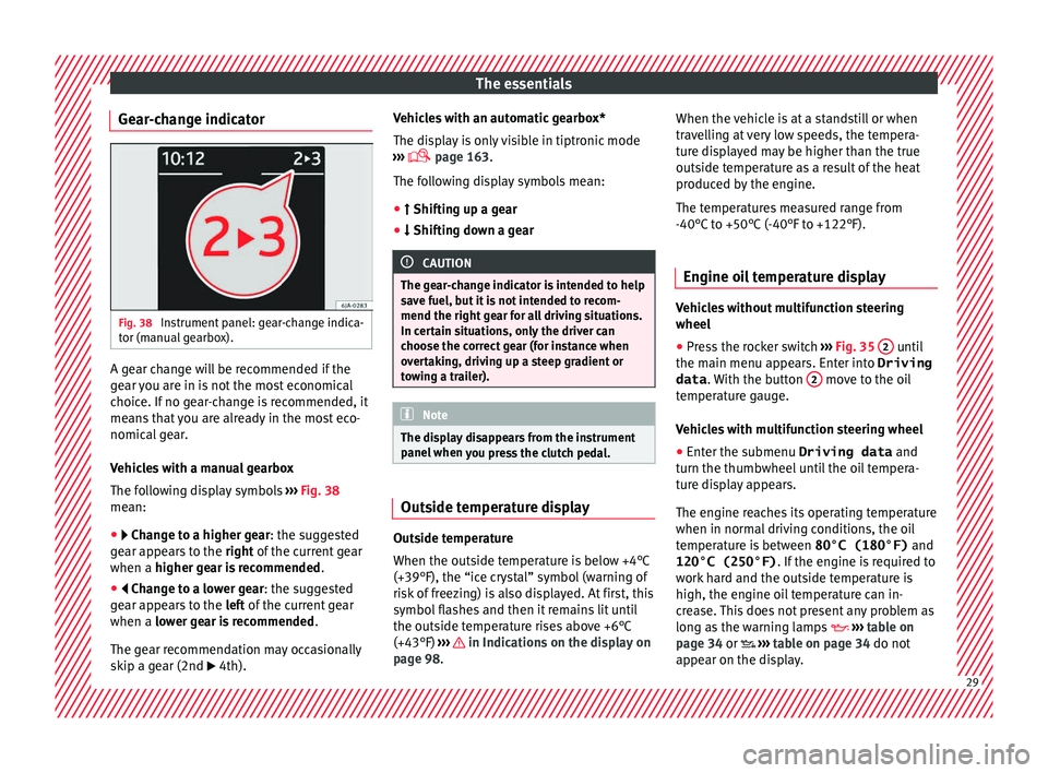
Gear-change indicator Fig. 38
Instrument panel: gear-change indica-
t or (m
anual
gearbox). A gear change will be recommended if the
g
e
ar
you are in is not the most economical
choice. If no gear-change is recommended, it
means that you are already in the most eco-
nomical gear.
Vehicles with a manual gearbox
The following display symbols ›››
Fig. 38
mean:
● Chan ge to a higher gear: the suggested
g
ear appears to the right of the current gear
when a higher gear is recommended .
● Change to a lower gear: the suggested
g
ear appears to the left of the current gear
when a lower gear is recommended .
The gear recommendation may occasionally
skip a gear (2nd 4th). Vehicles with an automatic gearbox*
The dis
p
lay is only visible in tiptronic mode
››› page 163.
The following display symbols mean:
● Shiftin g up a gear
●
Shifting down a gear CAUTION
The gear-change indicator is intended to help
sav e f
uel, but it is not intended to recom-
mend the right gear for all driving situations.
In certain situations, only the driver can
choose the correct gear (for instance when
overtaking, driving up a steep gradient or
towing a trailer). Note
The display disappears from the instrument
panel when
you press the clutch pedal. Outside temperature display
Outside temperature
When the outs
ide t
emper
ature is below +4°C
(+39°F), the “ice crystal” symbol (warning of
risk of freezing) is also displayed. At first, this
symbol flashes and then it remains lit until
the outside temperature rises above +6°C
(+43°F) ››› in Indications on the display on
p ag
e 98
. When the vehicle is at a standstill or when
travel
ling at very low speeds, the tempera-
ture displayed may be higher than the true
outside temperature as a result of the heat
produced by the engine.
The temperatures measured range from
-40°C to +50°C (-40°F to +122°F).
Engine oil temperature display Vehicles without multifunction steering
wheel
● Press the rocker switch ›
››
Fig. 35 2 until
the m ain menu ap
pe
ars. Enter into Driving
data . With the button 2 move to the oil
t emper
at
ure gauge.
Vehicles with multifunction steering wheel
● Enter the submenu Driving data and
turn the thumbwheel
until the oil tempera-
ture display appears.
The engine reaches its operating temperature
when in normal driving conditions, the oil
temperature is between 80°C (180°F) and
120°C (250°F) . If the engine is required to
work hard and the outside temperature is
high, the engine oil temperature can in-
crease. This does not present any problem as
long as the warning lamps ›››
table on
page 34 or ››› table on page 34 do not
appear on the display. 29
Page 32 of 248

The essentials
Additional consumers ●
Operation with the windscreen wiper lever*:
Pre s
s the rocker switch ››› Fig. 35 2 until the
main menu ap pe
ars. Enter into the section
Driving data . With the rocker switch,
move to the display Convenience con-
sumers .
● Operation with the multi-function steering
wheel*:
move with the buttons
or
to Driving data
and enter with
OK. Turn
the right thumbwheel until the Conven-
ience consumers display appears.
In addition, a scale will inform you of the cur-
rent sum of all the additional appliances.
Saving tips Tips on how to save fuel will be displayed in
c
ondition
s
that increase fuel consumption.
Follow them to reduce consumption. The indi-
cations appear automatically only with the ef-
ficiency programme. After a time, the tips will
disappear automatically.
If you wish to hide a saving tip immediately
after it appears, press any button on the
windscreen wiper lever*/multifunction steer-
ing wheel*. Note
● If y
ou hide a saving tip, it will reappear af-
ter you switch the ignition on again.
● The saving tips do not appear in all situa-
tions, but
rather with a large separation of
time. Speed warning device
The speed warning device warns the driver
when they h
av
e exceeded the pre-set speed
limit by 3 km/h (2 mph). An audible warning
signal sounds, and the warning lamp and
the driver message Speed limit excee-
ded! will be displayed simultaneously on the
instrument panel. The warning lamp
switches off after reducing speed below the
stored maximum limit.
Speed warning programming is recommen-
ded if you wish to be reminded of a maxi-
mum speed, such as when travelling in a
country with different speed limits or for a
maximum speed for winter tyres.
Setting speed limit warning
You can use the radio or the Easy Connect* to
set, alter or cancel the speed limit warning.
● Vehicles with radio : pres
s the SETUP button
> c ontr
o
l button Driver Assistant >
Speed warning . ●
Vehicles
with Easy Connect : press the button and the function button SETTINGS >
Driver assistance > Speed warning .
The w arnin
g limit
can be set from 30 to
240 km/h (20 to 149 mph). The adjustment
is made at 10 km/h (5 mph) intervals. Note
● Ple a
se bear in mind that, even with the
speed warning function, it is still important
to keep an eye on the vehicle speed with the
speedometer and to observe the legal speed
limits.
● The speed limit warning function in the ver-
sion for some c
ountries warns you at a speed
of 120 km/h (75 mph). This is a factory-set
speed limit. 30
Page 33 of 248
The essentials
Service intervals Fig. 39
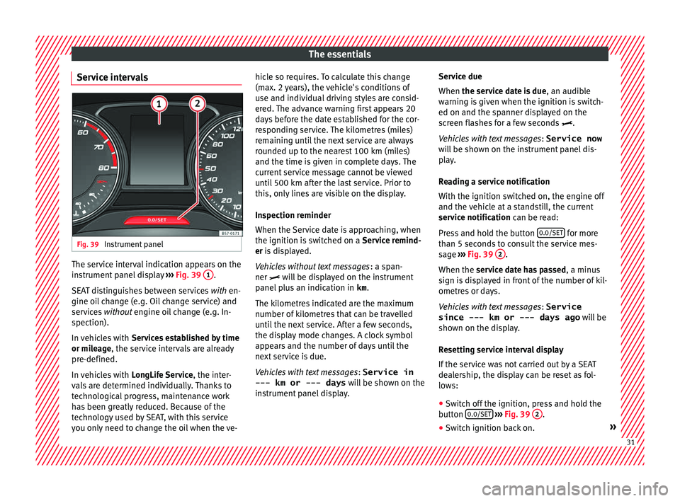
Instrument panel The service interval indication appears on the
in
s
trument
panel display ››› Fig. 39 1 .
S EA
T di
stinguishes between services with en-
gine oil change (e.g. Oil change service) and
services without engine oil change (e.g. In-
spection).
In vehicles with Services established by time
or mileage, the service intervals are already
pre-defined.
In vehicles with LongLife Service , the inter-
vals are determined individually. Thanks to
technological progress, maintenance work
has been greatly reduced. Because of the
technology used by SEAT, with this service
you only need to change the oil when the ve- hicle so requires. To calculate this change
(max. 2 y
ears), the vehicle's conditions of
use and individual driving styles are consid-
ered. The advance warning first appears 20
days before the date established for the cor-
responding service. The kilometres (miles)
remaining until the next service are always
rounded up to the nearest 100 km (miles)
and the time is given in complete days. The
current service message cannot be viewed
until 500 km after the last service. Prior to
this, only lines are visible on the display.
Inspection reminder
When the Service date is approaching, when
the ignition is switched on a Service remind-
er is displayed.
Vehicles without text messages : a span-
ner will be displayed on the instrument
panel plus an indication in km.
The kilometres indicated are the maximum
number of kilometres that can be travelled
until the next service. After a few seconds,
the display mode changes. A clock symbol
appears and the number of days until the
next service is due.
Vehicles with text messages : Service in
--- km or --- days will be shown on the
instrument panel display. Service due
When the servic
e date is due, an audible
warning is given when the ignition is switch-
ed on and the spanner displayed on the
screen flashes for a few seconds .
Vehicles with text messages : Service now
will be shown on the instrument panel dis-
play.
Reading a service notification
With the ignition switched on, the engine off
and the vehicle at a standstill, the current
service notification can be read:
Press and hold the button 0.0/SET for more
th an 5 sec
ond
s to consult the service mes-
sage ››› Fig. 39 2 .
When the ser v
ic
e date has passed , a minus
sign is displayed in front of the number of kil-
ometres or days.
Vehicles with text messages : Service
since --- km or --- days ago will be
shown on the display.
Resetting service interval display
If the service was not carried out by a SEAT
dealership, the display can be reset as fol-
lows:
● Switch off the ignition, press and hold the
button 0.0/S
ET
› ›
› Fig. 39 2 .
● Switch ignition back on. » 31
Page 35 of 248
The essentials
Warning lamps On the in s
trument
panelFig. 41
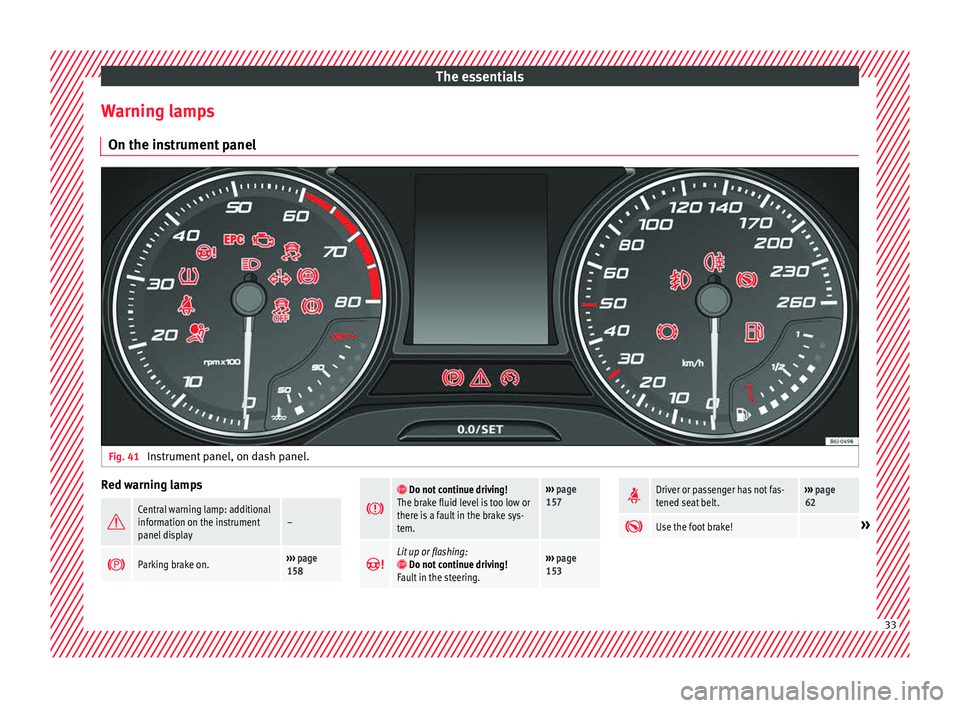
Instrument panel, on dash panel. Red warning lamps
Central warning lamp: additional
information on the instrument
panel display–
Parking brake on.›››
page
158
Do not continue driving!
The brake fluid level is too low or
there is a fault in the brake sys-
tem.››› page
157
Lit up or flashing: Do not continue driving!
Fault in the steering.››› page
153
Driver or passenger has not fas-
tened seat belt.›››
page
62
Use the foot brake!»
33
Page 36 of 248
The essentials
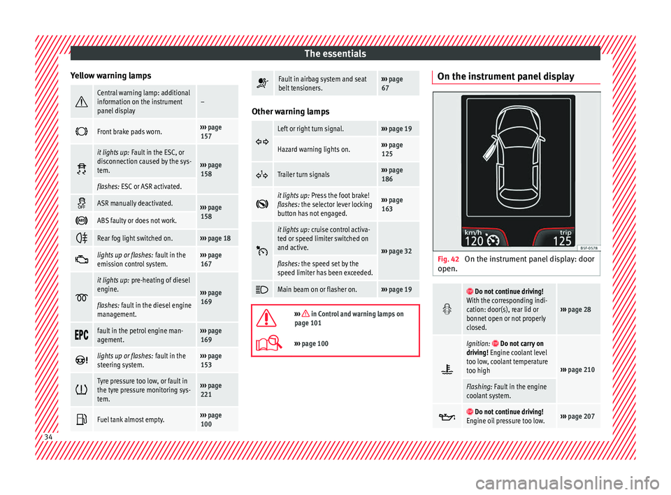
Yellow warning lamps Central warning lamp: additional
information on the instrument
panel display–
Front brake pads worn.›››
page
157
it lights up:
Fault in the ESC, or
disconnection caused by the sys-
tem.
››› page
158
flashes: ESC or ASR activated.
ASR manually deactivated.›››
page
158
ABS faulty or does not work.
Rear fog light switched on.›››
page 18
lights up or flashes:
fault in the
emission control system.››› page
167
it lights up:
pre-heating of diesel
engine.
››› page
169
flashes: fault in the diesel engine
management.
fault in the petrol engine man-
agement.›››
page
169
lights up or flashes:
fault in the
steering system.››› page
153
Tyre pressure too low, or fault in
the tyre pressure monitoring sys-
tem.›››
page
221
Fuel tank almost empty.›››
page
100
Fault in airbag system and seat
belt tensioners.›››
page
67 Other warning lamps
Left or right turn signal.›››
page 19
Hazard warning lights on.››› page
125
Trailer turn signals›››
page
186
it lights up:
Press the foot brake!
flashes: the selector lever locking
button has not engaged.››› page
163
it lights up:
cruise control activa-
ted or speed limiter switched on
and active.
››› page 32
flashes: the speed set by the
speed limiter has been exceeded.
Main beam on or flasher on.›››
page 19
››› in Control and warning lamps on
page 101
››› page 100 On the instrument panel display
Fig. 42
On the instrument panel display: door
open.
Do not continue driving!
With the corresponding indi-
cation: door(s), rear lid or
bonnet open or not properly
closed.
››› page 28
Ignition: Do not carry on
driving! Engine coolant level
too low, coolant temperature
too high
››› page 210
Flashing: Fault in the engine
coolant system.
Do not continue driving!
Engine oil pressure too low.››› page 207 34
Page 37 of 248
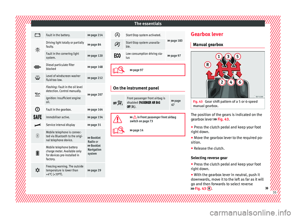
The essentials
Fault in the battery.›››
page 214
Driving light totally or partially
faulty.›››
page 84
Fault in the cornering light
system.››› page 120
Diesel particulate filter
blocked›››
page 168
Level of windscreen washer
fluid too low.›››
page 212
Flashing: Fault in the oil level
detection. Control manually.
›››
page 207Ignition: Insufficient engine
oil.
Fault in the gearbox.›››
page 164
Immobiliser active.›››
page 154
Service interval display›››
page 31
Mobile telephone is connec-
ted via Bluetooth to the origi-
nal telephone device.
›››
Booklet
Radio or
››› Booklet
Navigation
system
Mobile telephone battery
charge meter. Available only
for devices pre-installed in
factory.
Freezing warning. The outside
temperature is lower than
+4°C (+39°F).›››
page 29
Start-Stop system activated.
›››
page 183 Start-Stop system unavaila-
ble.
Low consumption driving sta-
tus›››
page 97
›››
page 97 On the instrument panel
Front passenger front airbag is
disabled (
).
››› page
67
››› in Front passenger front airbag
switch on page 73
››› page 14 Gearbox lever
M anua
l
gearbox Fig. 43
Gear shift pattern of a 5 or 6-speed
m anual
g
earbox. The position of the gears is indicated on the
g
e
arbo
x lever ››› Fig. 43.
● Press the clutch pedal and keep your foot
right down.
● Mo
ve the gearbox lever to the required po-
sition.
● Rel
ease the clutch.
Selecting r
everse gear
● Press the clutch pedal and keep your foot
right down.
● W
ith the gearbox lever in neutral, push it
downw
ards, move it to the left as far as it will
go and then forwards to select reverse
››› Fig. 43 R .
» 35
Page 47 of 248
The essentials
To replace a fuse
● Remove the fuse.
● Replace the blown fuse by one with an
iden tic
a
l amperage rating (same colour and
markings) and identical size.
● Replace the cover again or close the fuse
box lid.
B
ulbs
Bul
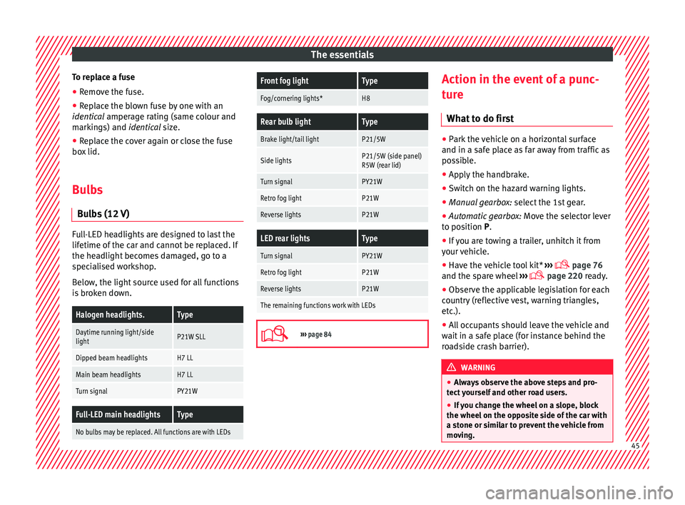
bs (12 V) Full-LED headlights are designed to last the
lif
etime of
the c
ar and cannot be replaced. If
the headlight becomes damaged, go to a
specialised workshop.
Below, the light source used for all functions
is broken down.
Halogen headlights.Type
Daytime running light/side
lightP21W SLL
Dipped beam headlightsH7 LL
Main beam headlightsH7 LL
Turn signalPY21W
Full-LED main headlightsType
No bulbs may be replaced. All functions are with LEDs
Front fog lightType
Fog/cornering lights*H8
Rear bulb lightType
Brake light/tail lightP21/5W
Side lightsP21/5W (side panel)
R5W (rear lid)
Turn signalPY21W
Retro fog lightP21W
Reverse lightsP21W
LED rear lightsType
Turn signalPY21W
Retro fog lightP21W
Reverse lightsP21W
The remaining functions work with LEDs
›››
page 84 Action in the event of a punc-
t
ur
e
Wh
at to do first ●
Park the vehicle on a horizontal surface
and in a saf e p
lace as far away from traffic as
possible.
● Apply the handbrake.
● Switch on the hazard warning lights.
● Manual gearbox: select the 1s
t gear.
● Automatic gearbox: Move the sel
ector lever
to position P.
● If you are towing a trailer, unhitch it from
your v
ehicle.
● Have the vehicle tool kit* ›››
page 76
and the spare wheel ›››
page 220 ready.
● Observe the applicable legislation for each
countr
y (reflective vest, warning triangles,
etc.).
● All occupants should leave the vehicle and
wait in a s
afe place (for instance behind the
roadside crash barrier). WARNING
● Alw a
ys observe the above steps and pro-
tect yourself and other road users.
● If you change the wheel on a slope, block
the wheel on the oppo
site side of the car with
a stone or similar to prevent the vehicle from
moving. 45
Page 51 of 248
The essentials
● Grip the end of the bo
x
spanner and turn
the wheel bolt about one turn anti-clockwise
››› Fig. 63.
Tightening wheel bolts ● Insert the box spanner onto the wheel bolt
as f
ar as it will go 1)
.
● Grip the box spanner as close to the end as
poss
ible and tighten the bolt firmly by turn-
ing clockwise. WARNING
The wheel bolts should only be loosened
slightly (about
one turn) before raising the
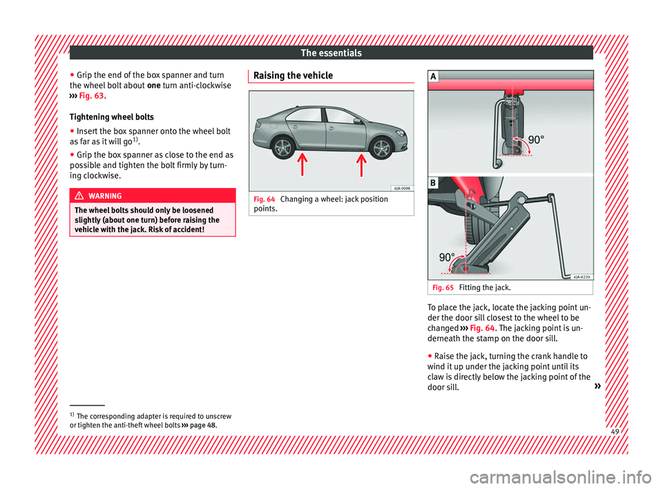
vehicle with the jack. Risk of accident! Raising the vehicle
Fig. 64
Changing a wheel: jack position
points. Fig. 65
Fitting the jack. To place the jack, locate the jacking point un-
der the door s
i
l
l closest to the wheel to be
changed ››› Fig. 64. The jacking point is un-
derneath the stamp on the door sill.
● Raise the jack, turning the crank handle to
wind it up u
nder the jacking point until its
claw is directly below the jacking point of the
door sill. »1)
The corresponding adapter is required to unscrew
or tighten the anti-thef t
wheel bolts ››› page 48. 49