warning Seat Toledo 2017 Workshop Manual
[x] Cancel search | Manufacturer: SEAT, Model Year: 2017, Model line: Toledo, Model: Seat Toledo 2017Pages: 248, PDF Size: 5.86 MB
Page 100 of 248
Operation
Time
● To set the time, keep the button ››
› Fig. 111
4 pressed for more than 3 seconds to select
the hour or minut e di
s
play.
● To continue setting the time, press the up-
per or lower p
art of the button 4 . Hold but-
t on do
wn t
o scroll through the numbers
quickly.
● Press the button 4 again in order to finish
settin g the time.
The time c an al
so be set on the Easy Connect
system using the button and the function
b utt
on
SETTINGS > Date and time
››› page 21.
Compass
With the ignition on and the navigation sys-
tem on, the cardinal point corresponding to
the direction of travel of the vehicle is dis-
played on the instrument panel.
Selector lever position
The selected gear is displayed on the side of
the selector lever and on the instrument pan-
el display. In positions D and S, and with the
Tiptronic, the corresponding gear is also dis-
played. Recommended gear (manual gearbox)
The r
ecommended g
ear in order to save fuel
is displayed on the instrument panel while
you are driving ›››
page 29.
Second speed display (mph or km/h)
In addition to the speedometer, the speed
can also be displayed in a different unit of
measurement (in miles or in km per hour).
This option cannot be deactivated in models
destined for countries in which the second
speed must always be visible.
The second speed display can be adjusted in
the Easy Connect system by means of the button and the function button SETTINGS >
Units › ›
›
page 21.
Speed warning
When the speed setting is exceeded, this will
be indicated on the instrument panel display.
This is very useful, for example when using
winter tyres that are not designed for driving
at the maximum speed of the vehicle
››› page 30.
The speed warning settings can be adjusted
in the Easy Connect system by means of the button and the function button SET-
TINGS > Driver Assistance
› ›
›
page 21. Start-Stop operating display
Updat
ed information relating to the status is
displayed on the instrument panel
››› page 183.
Low consumption driving status (ECO)*
Depending on the equipment, when driving,
the “ECO ” display appears on the instrument
panel when the vehicle is in low consump-
tion status.
Identifying letters on engine (MKB)
Hold the button ››› Fig. 111 4 down for more
th an 15 sec
ond
s to display the identifying
letters of the vehicle engine (MKB). To do
this, the ignition must be switched on and
the engine switched off. WARNING
Observe the safety warnings ›››
in Control
and warnin g l
amps on page 101. WARNING
Even though outside temperatures are above
freez in
g, some roads and bridges may be icy.
● At outside temperatures above +4°C
(+39°F), even when the “ice c
rystal” symbol
is not visible, there may still be patches of ice
on the road.
● The outside temperature sensor takes a
guideline meas
urement.98
Page 101 of 248
Instruments and warning lamps
Note
● Differ ent
versions of the instrument panel
are available and therefore the versions and
instructions on the display may vary. In the
case of displays without warning or informa-
tion texts, faults are indicated exclusively by
the warning lamps.
● Depending on the equipment, some set-
tings
and instructions can also be carried out
in the Easy Connect system.
● When several warnings are active at the
same time, the symbol
s are shown succes-
sively for a few seconds and will stay on until
the fault is rectified. Odometer
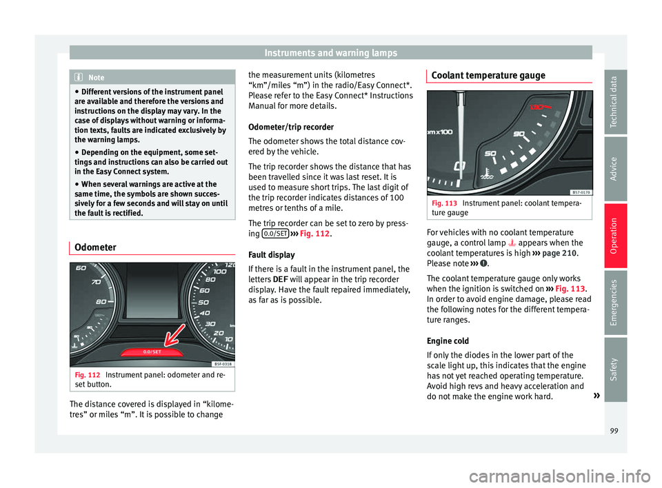
Fig. 112
Instrument panel: odometer and re-
set butt
on. The distance covered is displayed in “kilome-
tr
e
s” or mi
les “m”. It is possible to change the measurement units (kilometres
“km”/mile
s “m”) in the radio/Easy Connect*.
Please refer to the Easy Connect* Instructions
Manual for more details.
Odometer/trip recorder
The odometer shows the total distance cov-
ered by the vehicle.
The trip recorder shows the distance that has
been travelled since it was last reset. It is
used to measure short trips. The last digit of
the trip recorder indicates distances of 100
metres or tenths of a mile.
The trip recorder can be set to zero by press-
ing 0.0/SET
› ›
› Fig. 112
.
Fault display
If there is a fault in the instrument panel, the
letters DEF will appear in the trip recorder
display. Have the fault repaired immediately,
as far as is possible. Coolant temperature gauge Fig. 113
Instrument panel: coolant tempera-
t ur
e g
auge For vehicles with no coolant temperature
g
aug
e, a c
ontrol lamp appears when the
coolant temperatures is high ››› page 210.
Please note ››› .
The c oo
l
ant temperature gauge only works
when the ignition is switched on ››› Fig. 113.
In order to avoid engine damage, please read
the following notes for the different tempera-
ture ranges.
Engine cold
If only the diodes in the lower part of the
scale light up, this indicates that the engine
has not yet reached operating temperature.
Avoid high revs and heavy acceleration and
do not make the engine work hard. »
99
Technical data
Advice
Operation
Emergencies
Safety
Page 102 of 248
Operation
Normal temperature
If in norm
al
operations, the diodes light up
until the central zone, it means that the en-
gine has reached operating temperature. At
high outside temperatures and when making
the engine work hard, the diodes may contin-
ue lighting up and reach the upper zone. This
is no cause for concern, provided the control
lamp does not light up on the instrument
panel digital display.
Heat range
When the LEDs light up in the upper area of
the display and the control lamp appears
on the instrument panel display, the coolant
temperature is too high ››› page 210. CAUTION
● To en s
ure a long useful life for the engine,
avoid high revs, driving at high speed and
making the engine work hard for approxi-
mately the first 15 minutes when the engine
is cold. The phase until the engine is warm al-
so depends on the outside temperature. If
necessary, use the engine oil temperature*
››› page 207 as a guide.
● Additional lights and other accessories in
front of
the air inlet reduce the cooling effect
of the coolant. At high outside temperatures
and high engine loads, there is a risk of the
engine overheating.
● The front spoiler also ensures proper distri-
bution of the c
ooling air when the vehicle is moving. If the spoiler is damaged this can re-
duce the c
oo
ling effect, which could cause
the engine to overheat. Seek specialist assis-
tance. Fuel level gauge
Fig. 114
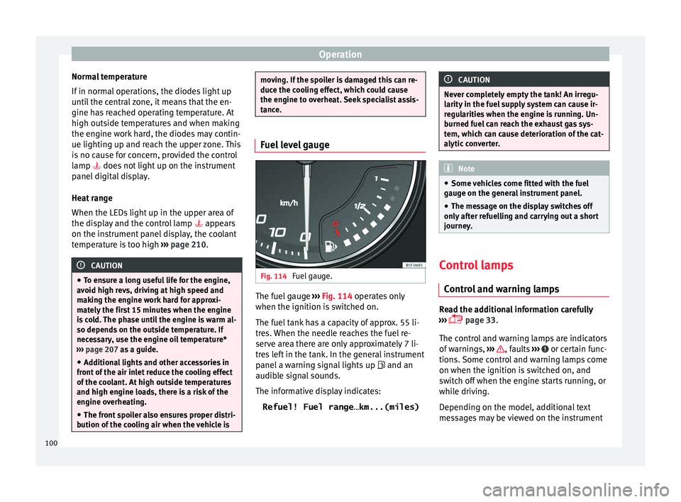
Fuel gauge. The fuel gauge
››
›
Fig. 114 operates only
when the ignition is switched on.
The fuel tank has a capacity of approx. 55 li-
tres. When the needle reaches the fuel re-
serve area there are only approximately 7 li-
tres left in the tank. In the general instrument
panel a warning signal lights up and an
audible signal sounds.
The informative display indicates:
Refuel! Fuel range…km...(miles) CAUTION
Never completely empty the tank! An irregu-
larity in the f
uel supply system can cause ir-
regularities when the engine is running. Un-
burned fuel can reach the exhaust gas sys-
tem, which can cause deterioration of the cat-
alytic converter. Note
● Some v ehic
les come fitted with the fuel
gauge on the general instrument panel.
● The message on the display switches off
only af
ter refuelling and carrying out a short
journey. Control lamps
C ontr
o
l and warning lamps Read the additional information carefully
› ›
›
page 33.
The control and warning lamps are indicators
of warnings, ››› , faults
››
›
or certain func-
tion s.
Some c
ontrol and warning lamps come
on when the ignition is switched on, and
switch off when the engine starts running, or
while driving.
Depending on the model, additional text
messages may be viewed on the instrument
100
Page 103 of 248
Introduction to the Easy Connect system*
panel display. These may be purely informa-
tiv e or they
m
ay be advising of the need for
action ››› page 96.
Depending upon the equipment fitted in the
vehicle, instead of a warning lamp, some-
times a symbol may be displayed on the in-
strument panel.
When certain control and warning lamps are
lit, an audible warning is also heard. WARNING
If the warning lamps and messages are ignor-
ed, the v ehic
le may stall in traffic, or may
cause accidents and severe injuries.
● Never ignore the warning lamps or text
mess
ages.
● Stop the vehicle safely as soon as possible.
● Park the vehicle away from traffic and en-
sure th
at there are no highly flammable ma-
terials under the vehicle that could come into
contact with the exhaust system (e.g. dry
grass, fuel).
● A faulty vehicle represents a risk of acci-
dent for the driv
er and for other road users. If
necessary, switch on the hazard warning
lamps and put out the warning triangle to ad-
vise other drivers.
● Before opening the bonnet, switch off the
engine and al
low it to cool.
● In any vehicle, the engine compartment is a
hazar
dous area and could cause severe inju-
ries ››› page 204. CAUTION
Failure to heed the control lamps and text
mes s
ages when they appear may result in
faults in the vehicle. Introduction to the Easy
C
onnect
sy
stem*
System settings (CAR)* CAR menu Read the additional information carefully
›› ›
page 21
To select the settings menus, press the Easy
Connect button and the
S
ET
TINGS func-
tion b utt
on.
The act
ual number of menus available and
the name of the various options in these me-
nus will depend on the vehicle’s electronics
and equipment.
When the function button check box is activa-
ted , the function is active.
Pressing the menu button will always take
y ou t
o the l
ast menu used.
Any changes made using the settings menus
are automatically saved on closing those me-
nus.
Function buttons in the vehicle settings
menuPage
ESC system››› page 158
Tyres››› page 221» 101
Technical data
Advice
Operation
Emergencies
Safety
Page 104 of 248
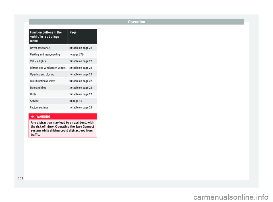
OperationFunction buttons in the
vehicle settings
menuPage
Driver assistance››› table on page 22
Parking and manoeuvring››› page 170
Vehicle lights››› table on page 22
Mirrors and windscreen wipers››› table on page 22
Opening and closing››› table on page 22
Multifunction display››› table on page 22
Date and time››› table on page 22
Units››› table on page 22
Service››› page 31
Factory settings››› table on page 22 WARNING
Any distraction may lead to an accident, with
the risk of
injury. Operating the Easy Connect
system while driving could distract you from
traffic. 102
Page 111 of 248
Opening and closing
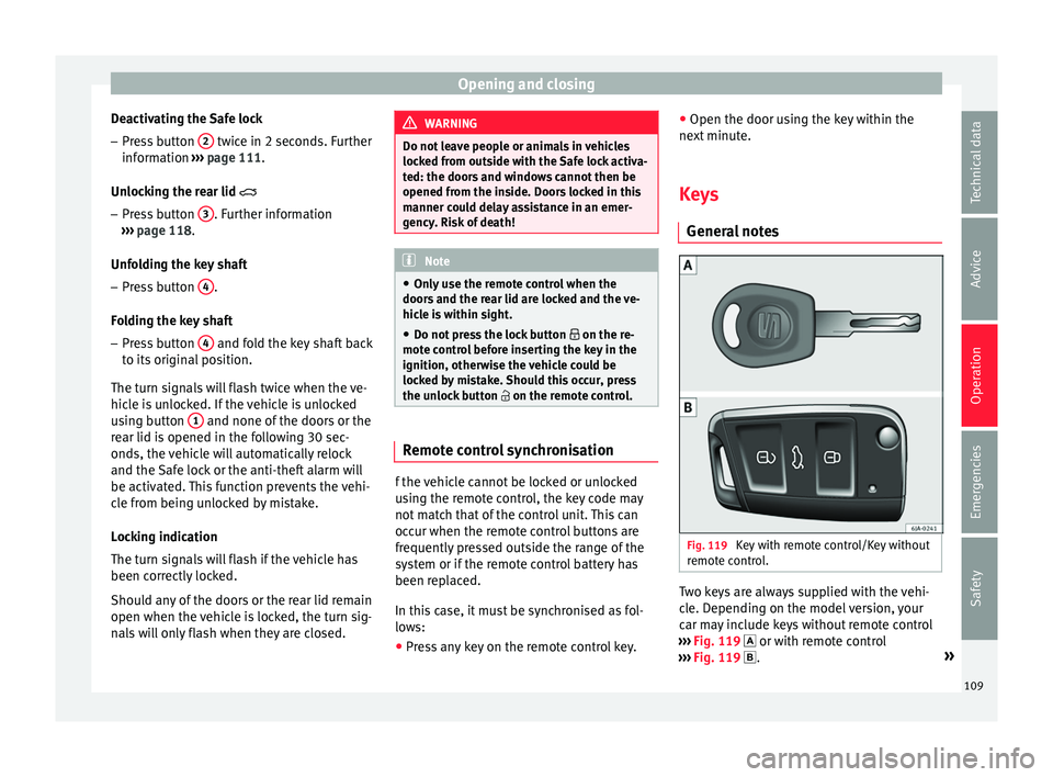
Deactivating the Safe lock – Press button 2 twice in 2 seconds. Further
inf orm
ation ›
›› page 111.
Unlocking the rear lid
– Press button 3 . Further information
› ›
›
page 118.
Unfolding the key shaft
– Press button 4 .
F o
l
ding the key shaft
– Press button 4 and fold the key shaft back
t o its
origin
al position.
The turn signals will flash twice when the ve-
hicle is unlocked. If the vehicle is unlocked
using button 1 and none of the doors or the
r e
ar lid i
s opened in the following 30 sec-
onds, the vehicle will automatically relock
and the Safe lock or the anti-theft alarm will
be activated. This function prevents the vehi-
cle from being unlocked by mistake.
Locking indication
The turn signals will flash if the vehicle has
been correctly locked.
Should any of the doors or the rear lid remain
open when the vehicle is locked, the turn sig-
nals will only flash when they are closed. WARNING
Do not leave people or animals in vehicles
lock ed fr
om outside with the Safe lock activa-
ted: the doors and windows cannot then be
opened from the inside. Doors locked in this
manner could delay assistance in an emer-
gency. Risk of death! Note
● Only u
se the remote control when the
doors and the rear lid are locked and the ve-
hicle is within sight.
● Do not press the lock button on the re-
mote c
ontrol before inserting the key in the
ignition, otherwise the vehicle could be
locked by mistake. Should this occur, press
the unlock button on the remote control. Remote control synchronisation
f the vehicle cannot be locked or unlocked
u
s
in
g the remote control, the key code may
not match that of the control unit. This can
occur when the remote control buttons are
frequently pressed outside the range of the
system or if the remote control battery has
been replaced.
In this case, it must be synchronised as fol-
lows:
● Press any key on the remote control key. ●
Open the door usin
g the key within the
next minute.
Keys General
notes Fig. 119
Key with remote control/Key without
r emot
e c
ontrol. Two keys are always supplied with the vehi-
c
l
e. D
epending on the model version, your
car may include keys without remote control
››› Fig. 119 or with remote control
››› Fig. 119 . »
109
Technical data
Advice
Operation
Emergencies
Safety
Page 112 of 248
Operation
WARNING
● Never l e
ave the key inside whenever you
leave the vehicle - even if only for a moment.
This is particularly important if children are
to remain in the vehicle. Children might start
the engine or some other electrical compo-
nent, e.g. electric windows. Risk of injury!
● Wait until the vehicle has completely stop-
ped before t
aking the key out of the ignition.
Otherwise the steering wheel may lock sud-
denly. Risk of accident! CAUTION
● Eac h k
ey contains electronic components
and must, therefore, be protected from damp-
ness and strong vibrations.
● Keep the grooves in the key shaft clean.
Any dir
t (fibre from clothing, dust, etc.) has a
negative impact on locks, ignition, etc. Note
Should a key be lost, request a duplicate key
from an Authori sed S
EAT dealer. Replacing the battery in the remote
c
ontr
o
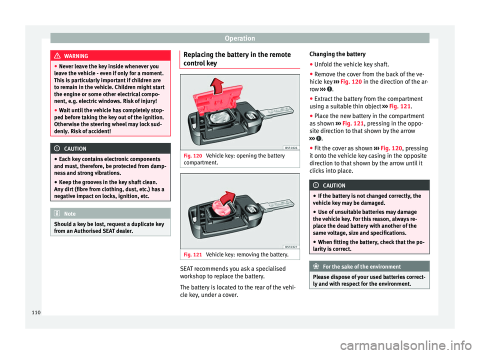
l key Fig. 120
Vehicle key: opening the battery
c omp
ar
tment. Fig. 121
Vehicle key: removing the battery. SEAT recommends you ask a specialised
w
ork
shop t
o replace the battery.
The battery is located to the rear of the vehi-
cle key, under a cover. Changing the battery
● Unfold the vehicle key shaft.
● Remove the cover from the back of the ve-
hicle k
ey ››› Fig. 120 in the direction of the ar-
row ››› .
● Extract the battery from the compartment
u s
in
g a suitable thin object ››› Fig. 121.
● Place the new battery in the compartment
as sho
wn ››› Fig. 121, pressing in the oppo-
site direction to that shown by the arrow
››› .
● Fit the cover as shown ››
›
Fig. 120 , pressing
it onto the vehicle key casing in the opposite
direction to that shown by the arrow until it
clicks into place. CAUTION
● If the b att
ery is not changed correctly, the
vehicle key may be damaged.
● Use of unsuitable batteries may damage
the vehic
le key. For this reason, always re-
place the dead battery with another of the
same voltage, size and specifications.
● When fitting the battery, check that the po-
larity i
s correct. For the sake of the environment
Please dispose of your used batteries correct-
ly and w ith r
espect for the environment.110
Page 113 of 248
Opening and closing
Note
If it is not possible to unlock or lock the vehi-
cl e w
ith the remote control key once the bat-
tery has been replaced, it will need to be re-
synchronised ››› page 109. Central locking system
Genera l
notesAll of
the doors, the rear lid and the fuel cap
fl ap 1)
w
ill unlock at the same time when the
central locking system is used.
Warning lamp on the driver door
Once the doors are locked, the warning lamp
will flash quickly for 2 seconds and then at a
slower rate.
If the vehicle is locked with Safe lock engag-
ed ›››
page 112, the warning lamp on the
driver door will flash quickly for 2 seconds
before switching off for 30 seconds and then
flashing at a slower rate.
If the warning lamp flashes quickly for 2 sec-
onds and then remains switched on before
flashing at a slower rate after 30 seconds,
there is a fault in the interior monitor and tow-away protection system
›››
page 117. Go
to a technical service.
Individualised settings Unlocking single doors
This
option
al function unlocks the driver door
only. The other doors remain locked and are
only unlocked when the next command is giv-
en (unlock).
Automatic unlock and lock
The doors and the rear lid are locked auto-
matically when the vehicle reaches a speed
of about 15 km/h (9 mph).
The doors unlock automatically when the key
is removed from the ignition. Additionally,
the driver or front passenger can unlock the
doors by pressing the ›››
page 113 central
lock button or by pulling the front door han-
dle. WARNING
Locking the doors prevents intruders from
gettin g int
o the car, e.g. while waiting at in-
tersections. However, it can also delay assis-
tance in the event of an accident. Risk of
death! Note
● Activ ation of
the single door setting can be
requested at your SEAT dealer.
● In the event of an accident in which the air-
bags
deploy, the doors will be automatically
unlocked for easier access and assistance.
● If the central locking system should fail to
work at
any time, only the driver door can be
locked or unlocked using the key
››› page 112. All other doors and the rear lid
can be operated manually.
–Manual release ›››
page 10.
– Manual release mechanism for the rear
lid ›››
page 10. 1)
Valid for vehicles with a keyless fuel tank cap.
111
Technical data
Advice
Operation
Emergencies
Safety
Page 114 of 248
Operation
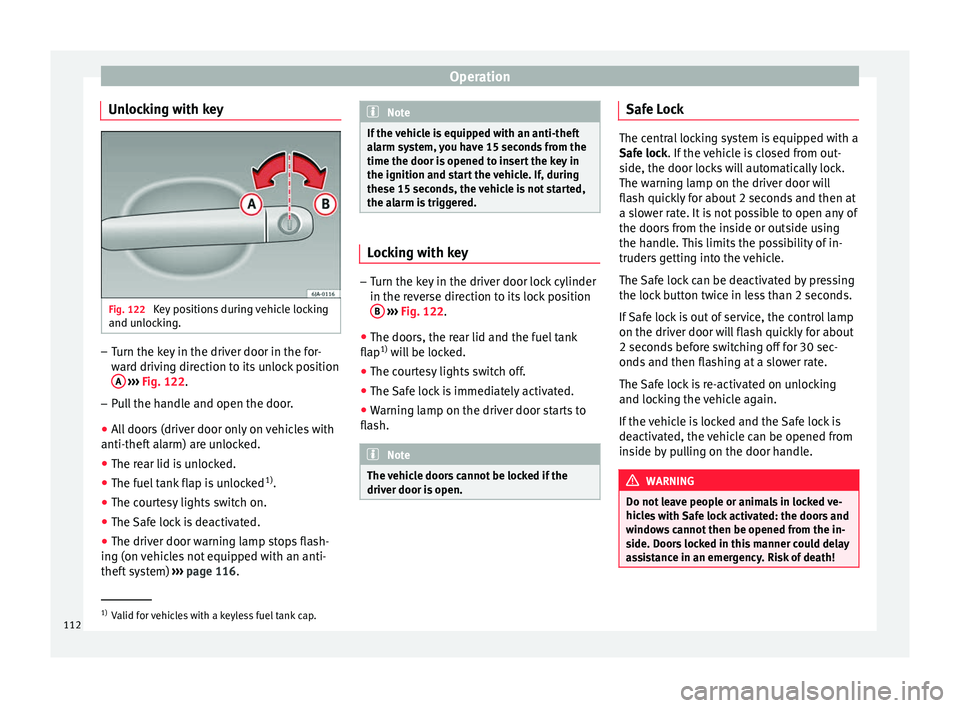
Unlocking with key Fig. 122
Key positions during vehicle locking
and u n
loc
king. –
Turn the key in the driver door in the for-
war
d driv
ing direction to its unlock position
A
› ›
›
Fig. 122.
– Pull the handle and open the door.
● All doors (driver door only on vehicles with
anti-theft al
arm) are unlocked.
● The rear lid is unlocked.
● The fuel tank flap is unlocked 1)
.
● The courtesy lights switch on.
● The Safe lock is deactivated.
● The driver door warning lamp stops flash-
ing (on v
ehicles not equipped with an anti-
theft system) ›››
page 116. Note
If the vehicle is equipped with an anti-theft
al arm sy
stem, you have 15 seconds from the
time the door is opened to insert the key in
the ignition and start the vehicle. If, during
these 15 seconds, the vehicle is not started,
the alarm is triggered. Locking with key
–
Turn the key in the driver door lock cylinder
in the rev er
se direction to its lock position
B
› ›
›
Fig. 122.
● The doors, the rear lid and the fuel tank
flap 1)
wi
ll be locked.
● The courtesy lights switch off.
● The Safe lock is immediately activated.
● Warning lamp on the driver door starts to
flash. Note
The vehicle doors cannot be locked if the
driver door i s
open. Safe Lock
The central locking system is equipped with a
Safe loc
k
. If the vehicle is closed from out-
side, the door locks will automatically lock.
The warning lamp on the driver door will
flash quickly for about 2 seconds and then at
a slower rate. It is not possible to open any of
the doors from the inside or outside using
the handle. This limits the possibility of in-
truders getting into the vehicle.
The Safe lock can be deactivated by pressing
the lock button twice in less than 2 seconds.
If Safe lock is out of service, the control lamp
on the driver door will flash quickly for about
2 seconds before switching off for 30 sec-
onds and then flashing at a slower rate.
The Safe lock is re-activated on unlocking
and locking the vehicle again.
If the vehicle is locked and the Safe lock is
deactivated, the vehicle can be opened from
inside by pulling on the door handle. WARNING
Do not leave people or animals in locked ve-
hicl e
s with Safe lock activated: the doors and
windows cannot then be opened from the in-
side. Doors locked in this manner could delay
assistance in an emergency. Risk of death! 1)
Valid for vehicles with a keyless fuel tank cap.
112
Page 115 of 248
Opening and closing
Note
● The anti-theft a
larm switches on automati-
cally when the vehicle is locked, even if the
Safe lock is deactivated. The Vehicle interior
monitoring, however, is not activated.
● Given that the Safe function will be activa-
ted on lock
ing the vehicle, CHECK DEADLOCK
will be shown on the general instrument pan-
el display. On vehicles equipped with an in-
formative display, Caution SAFE! On- board documentation! Central locking button
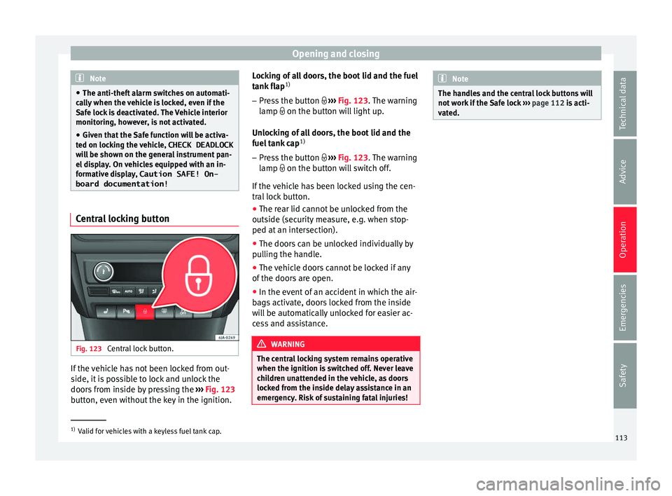
Fig. 123
Central lock button. If the vehicle has not been locked from out-
s
ide, it
i
s possible to lock and unlock the
doors from inside by pressing the ›››
Fig. 123
button, even without the key in the ignition. Locking of all doors, the boot lid and the fuel
tank fl
ap1)
– Press the button ›››
Fig. 123. The warning
lamp on the button will light up.
Unlocking of all doors, the boot lid and the
fuel tank cap 1)
– Press the button ›››
Fig. 123. The warning
lamp on the button will switch off.
If the vehicle has been locked using the cen-
tral lock button.
● The rear lid cannot be unlocked from the
outside (security
measure, e.g. when stop-
ped at an intersection).
● The doors can be unlocked individually by
pul
ling the handle.
● The vehicle doors cannot be locked if any
of the doors
are open.
● In the event of an accident in which the air-
bags
activate, doors locked from the inside
will be automatically unlocked for easier ac-
cess and assistance. WARNING
The central locking system remains operative
when the ignition is sw
itched off. Never leave
children unattended in the vehicle, as doors
locked from the inside delay assistance in an
emergency. Risk of sustaining fatal injuries! Note
The handles and the central lock buttons will
not w ork
if the Safe lock ››› page 112 is acti-
vated. 1)
Valid for vehicles with a keyless fuel tank cap.
113
Technical data
Advice
Operation
Emergencies
Safety